Advertisement
Quick Links
SELECTRONIC
HARD-WIRED AC POWERED PROXIMITY
TOILET FLUSH VALVE
1.1, 1.28, 1.6, 1.6/1.1 & 1.28/1.1
Certified to comply with ASME A112.19.2M
© 2011 AS America, Inc.
M965219 REV. 1.7
NOTE TO INSTALLER: Please give this manual to the customer after installation.
To learn more about American Standard Faucets visit our website at: www.americanstandard-us.com
or U.S. customer's e-mail us at: faucetsupport@americanstandard.com
For Parts, Service, Warranty or other Assistance,
1-800-442-1902 (In Canada: 1-800-387-0369)
please call
®
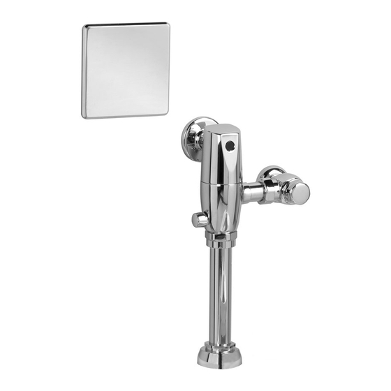
Exposed Flushometer
for 1-1/2" Top Spud Bowls
CLOG RESISTANT
• Self-cleaning piston valve prevents clogging and reduces maintenance.
ONE SENSOR FITS ALL
• Only 1 sensor for entire Selectronic™ line of faucets, urinals, and ush valves.
• Range can be adjusted manually or with optional remote control.
(In Toronto Area only: 1-905-3061093)
(In Toronto Area only: 1-905-3061093)
MODEL NUMBERS
6067.111
6068.161
6067.721
6068.121
6067.761
6068.111
6067.121
6068.761
6067.161
6068.721
Advertisement

Related Manuals for American Standard SELECTRONIC 6067.111


Summary of Contents for American Standard SELECTRONIC 6067.111
- Page 1 M965219 REV. 1.7 NOTE TO INSTALLER: Please give this manual to the customer after installation. To learn more about American Standard Faucets visit our website at: www.americanstandard-us.com or U.S. customer's e-mail us at: faucetsupport@americanstandard.com For Parts, Service, Warranty or other Assistance,...
- Page 2 M965219 REV. 1.8 NOTE TO INSTALLER: Please give this manual to the customer after installation. To learn more about American Standard Faucets visit our website at: www.americanstandard-us.com or U.S. customer's e-mail us at: faucetsupport@americanstandard.com For Parts, Service, Warranty or other Assistance,...
-
Page 3: General Description
Fig. 1 GENERAL DESCRIPTION: Roughing-in Dimensions SEE DETAIL “A” SELECTRONIC™ PROXIMITY TOILET FLUSH VALVE ˚ Exposed Flushometer for 1-1/2" Top Spud Fixtures DETECTION ZONE Right or Left Hand Installation 400mm-800mm Exclusive, self cleaning piston-type flush (15-3/4" TO 31-1/2") (Section 7) for converting Flush valve with proximity operation and Valve to Left Hand Installation. -
Page 4: Installation
INSTALLATION Fig.3 (TOP SPUD FIXTURE ILLUSTRATED) Hubbel-RACO 8231 4" 127mm ELECTRICAL BOX 127mm INSTALL ELECTRICAL BOX (5") OR EQUIVALENT BY (5") CONTRACTOR ASSEMBLY; Fig. 3 Hubbel-RACO 779 1. Drill a 2" diameter hole in the finished wall for the conduit tube from the flush valve at the dimension 305mm shown. - Page 5 Fig.4c Hubbel-RACO 8231 4" ELECTRICAL BOX OR EQUIVALENT BY CONTRACTOR BLACK & WHITE POWER CONNECTIONS Unit #1 Unit #2 Unit #3 FOR AC-VERSION (MULTI HOOK-UP); Fig. 4c 1. Contractor to supply ELECTRICAL BOX (1). Mount POWER SUPPLY (2) into ELECTRICAL BOX (1). Connect White and Black power connections to POWER SUPPLY.
- Page 6 INSTALL THE SWEAT SOLDER Fig.5 ADAPTER; Fig. 5 FINISHED WALL CENTER LINE OF Turn water supplies off CAUTION FIXTURE SPUD before beginning Note: Install Optional Sweat Solder Adapter (Supplied) for copper pipe supply line. Fig. 5. (A-B)= 1. Measure the distance (A) from the finished wall to the 32mm (1-1/4") center of the inlet spud on the fixture.
- Page 7 FLUSH OUT SUPPLY LINES; Fig. 8 Fig. 8 1. Remove COVER (1) from SUPPLY STOP (2). REMOVE COVER 2. With a flat blade screwdriver open SUPPLY STOP (2). 3. Turn on water supply to flush line of any debris or sediment.
- Page 8 INSTALL FLUSH VALVE; Fig. 10b Fig. 10b 121mm,+13mm, -6mm (4-3/4")(+1/2", -1/4") 1. Pull the DOWN TUBE (7) up to meet the threaded FLUSH VALVE CONNECTION (8) and hand tighten the VACUUM BREAKER COUPLING NUT (6). Align all components of the flush valve assembly. Fig. 10b. 2.
- Page 9 HOW TO SET DETECTION RANGE Fig. 13 (If Required) ; Fig. 13 & 14 Note: The detection distance is preset and is ideal for most installations. Should an adjustment be required follow the steps below. 1. To remove the FRONT PANEL (1), insert WIRE KEY (2) (supplied) into the two holes located at the bottom of the FRONT PANEL (1).
- Page 10 M965219 REV. 1.7...
Need help?
Do you have a question about the SELECTRONIC 6067.111 and is the answer not in the manual?
Questions and answers