American Standard SELECTRONIC 606B.111 Installation Instructions Manual
Exposed toilet flush valve ac powered proximity
Hide thumbs
Also See for SELECTRONIC 606B.111:
- Installation instructions manual (34 pages) ,
- Manual (1 page)
Advertisement
SELECTRONIC
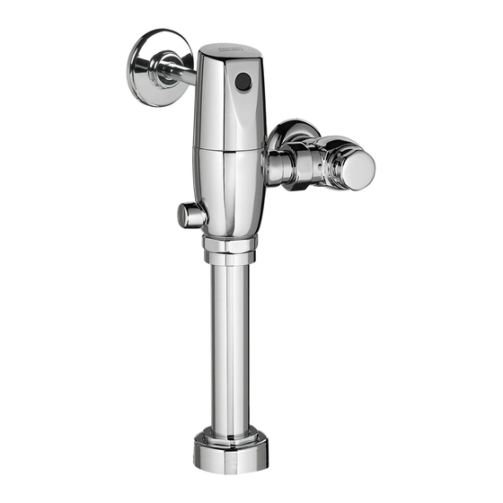
EXPOSED TOILET FLUSH VALVE
AC POWERED PROXIMITY
1.1, 1.28, 1.6,
1.6/1.1 & 1.28/1.1 GPF
Certified to comply with ASME A112.19.2
© 2018 AS America, Inc.
NOTE TO INSTALLER: Please give this manual to the customer after installation.
To learn more about American Standard Selectronic
or e-mail us at: CRTTEAM@americanstandard.com
For Parts, Service, Warranty or other Assistance,
please call (844) CRT-TEAM / (844) 278-8326 (In Canada: 1-800-387-0369)
© 2018 AS America Inc.
®
606B.111 606B.121 606B.161 606B.721 606B.761
COVER PLATE
(Required for Front Installation Only)
Exposed Flush Valve
for 1-1/2" Top Spud Bowls
CAUTION: Use only American Standard supplied
transformers and cable sets. Using non-AS supplied
cables, or cutting, splicing or modifying any components
will void the warranty.
Products visit our website at: www.americanstandard-us.com
®
(In Toronto Area only: 1-905-306-1093)
1
MODEL NUMBERS
M965644 EN REV. 2.1 (9/18)
Advertisement
Table of Contents

Related Manuals for American Standard SELECTRONIC 606B.111


Summary of Contents for American Standard SELECTRONIC 606B.111
- Page 1 Certified to comply with ASME A112.19.2 © 2018 AS America, Inc. NOTE TO INSTALLER: Please give this manual to the customer after installation. To learn more about American Standard Selectronic Products visit our website at: www.americanstandard-us.com ® or e-mail us at: CRTTEAM@americanstandard.com...
-
Page 2: Care Instructions
Thank you for selecting American-Standard...the benchmark of fine quality for over 100 years. To ensure that your installation proceeds smoothly--please read these instructions carefully before you begin. All American Standard Products Are Water Tested At Our Factory. UNPACKING Some Residual Water May Remain In The Valve During Shipping. -
Page 3: General Description
See (Section 5) for converting Flush FLUSH VALVE for 1-1/2" Top Spud Fixtures Valve to Left Hand Installation. CAUTION: Use only American Standard supplied transformers and cable sets. Using non-AS supplied cables, or cutting, splicing or modifying any components 4" (102 mm) SQ. BOX DEVICE COVER (PLASTER RING). - Page 4 RECOMMENDED TOOLS; Fig. 2. Fig. 2 1. Teflon Tape 2. Flat Blade Screwdriver 3. Adjustable Wrench 4. Tape Measure 5. Hacksaw 6. Tubing Cutter 7. File 8. For Sweat Connection; Solder and Torch 9. 2.5 mm Hex Wrench 10. 1.5 mm Hex Wrench PRIOR TO INSTALLATION •...
- Page 5 FLUSH VALVE INSTALLATION Fig.3 FINISHED WALL CENTER LINE OF FIXTURE SPUD INSTALL SWEAT ADAPTER; Fig. 3 Turn water supplies off before CAUTION beginning (A-B)= Note: Install Optional Sweat Adapter (Supplied) for copper pipe supply line. 32mm (1-1/4") FILE EDGES 1. Measure the distance (A) from the finished wall to the center of the inlet spud on the fixture.
- Page 6 FLUSH OUT SUPPLY LINES; Fig. 6 Fig. 6 1. Remove STOP VALVE COVER (1) from STOP VALVE (2). REMOVE COVER 2. Open STOP VALVE (2) with a flat blade screwdriver. 3. Turn on water supply to flush line of any debris or sediment.
-
Page 7: Electrical Installation
ELECTRICAL INSTALLATION Fig. 9 10' EXTENSION INSTALL POWER SUPPLY AND MAKE ELECTRICAL CONNECTIONS; Fig. 9 (remote and front installation) Ensure that the line power to bathroom CAUTION is OFF prior to making connections. BLACK & WHITE 1. Connect Black and White power connections to AC POWER CONNECTIONS TRANSFORMER (1). - Page 8 4. Place Y-ADAPTERS (2) into respective electrical box. 5. Reconnect the first unit’s Y-ADAPTER (2a) to power supply once all daisy-chain unit connections have been made. CAUTION: Use only American Standard supplied transformers and cable sets. Using non-AS supplied cables, or cutting, splicing or modifying any components will void the warranty.
-
Page 9: Maintenance
(3) into the two Slots located on the top edge of the COVER PLATE FRAME (1). Push on bottom until it snaps into place. TABS CAUTION: Use only American Standard supplied transformers and cable sets. Using non-AS supplied cables, or cutting, splicing or modifying any components will void the warranty. MAINTENANCE Fig. - Page 10 SET DETECTION RANGE Fig. 13 (if Required); Fig. 13 & 14 Note: The detection distance is preset and ideal for most installations. Should an adjustment be required, follow the steps below. 1. To remove the COVER PLATE (1), insert WIRE KEY (2) (supplied) into the two holes located at the bottom of the COVER PLATE (1).
-
Page 11: Troubleshooting Flowcharts
Pro d uct names l i s te d h ere in are t rad em ar k s of AS A mer i ca , I nc. © 2018 DOES FLUSHING STOP? To learn more about American Standard Selectronic ®... - Page 12 Weekdays 8:00 a.m. to 7:00 p.m. EST Pro du ct names lis ted h erein a re trad ema r k s of AS Amer ic a , Inc. ©2018 To learn more about American Standard Selectronic Products visit our website at: ®...
- Page 13 Weekdays 8:00 a.m. to 7:00 p.m. EST Prod u ct names liste d h ere in are tra d em ar k s of AS A mer ic a, I nc . © 2018 To learn more about American Standard Selectronic Products visit our website at: ®...
Need help?
Do you have a question about the SELECTRONIC 606B.111 and is the answer not in the manual?
Questions and answers