Table of Contents
Advertisement
Quick Links
Read this entire installation manual to ensure proper installation.
Installation
When finished with the installation, file this manual with the owner or
maintenance department.
Separate parts from packaging and make sure all parts are accounted
Packing List
for before discarding any packaging material. If any parts are
IS
T H
E
S ID
missing, do not begin installation until you obtain the missing parts.
U P
Water supply requires a flowing pressure of at least 20 psi, but no
greater than 80 psi.
Make sure that all water supply lines have been flushed and then
completely turned off before beginning installation. Debris in supply
lines can cause valves to malfunction.
Hardware supplied by installer must be appropriate for wall
construction. Wall anchors used must have a minimum pull-out
rating of 1,000 lbs.
The Adaptive® Infrared control must be connected with a 24 VAC
Class II transformer. Connections to 110 VAC can cause personal
injury and will result in damage to the electronics.
Product warranties may be found under "Product Information" on our
web site at www.bradleycorp.com.
215-1176 Rev R; EN 06-915C
© 2005 Bradley Corporation
Page 1 of 17
10-28-2005
Installation
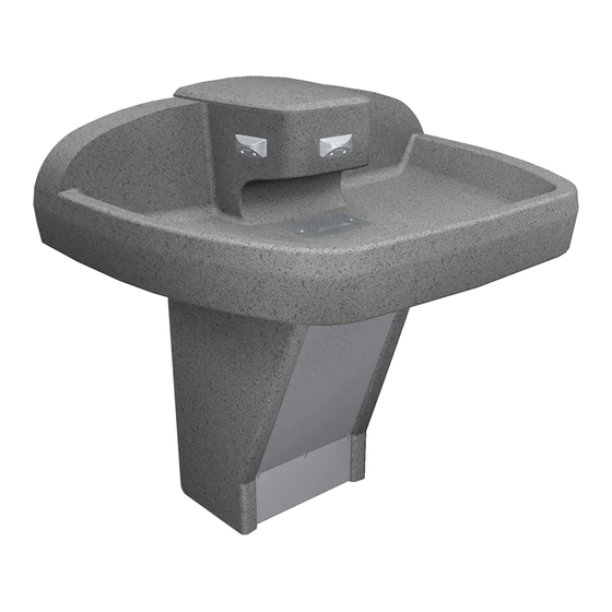
MF2933/IR
Terreon
Washfountain with Adaptive
Infrared Control
(Standard* & Juvenile Height)
* Standard Height is ADA Compliant
IMPORTANT!
®
™
Tri-Fount
P.O. Box 309, Menomonee Falls, WI 53052-0309
Phone: 1-800-BRADLEY Fax: (262) 251-5817
http:\\www.bradleycorp.com
Advertisement
Chapters
Table of Contents
Troubleshooting

Related Manuals for Bradley Terreon Tri-Fount MF2933/IR


Summary of Contents for Bradley Terreon Tri-Fount MF2933/IR
- Page 1 Product warranties may be found under "Product Information" on our web site at www.bradleycorp.com. 215-1176 Rev R; EN 06-915C P.O. Box 309, Menomonee Falls, WI 53052-0309 Phone: 1-800-BRADLEY Fax: (262) 251-5817 © 2005 Bradley Corporation http:\\www.bradleycorp.com Page 1 of 17...
-
Page 2: Table Of Contents
• Pipe sealant and plumber’s putty • 110 VAC power source for 110/24 VAC plug-in transformer supplied • OPTIONAL: Bradley recommends installing an electrical cut-off switch to the unit. This feature prevents accidental water delivery during regular maintenance and service. -
Page 3: Pre-Installation Information
The Terreon® Tri-Fount™ with Adaptive Infrared is designed to comply with all ADA guidelines on reaches, clearances and operation when mounted at standard height dimensions by the installer (see page 5 of this instruction manual for rough-in and mounting dimensions). Bradley Corporation • 215-1176 Rev. R; EN 06-915C 10-28-2005... -
Page 4: Parts Included With The Tri-Fount
Installation Parts included with the Tri-Fount™ Separate all parts from packaging materials and ensure you have all the parts required for assembly. If any parts are missing, do not attempt to assemble the Bradley Terreon ® Tri-Fount™ Washfountain until you obtain all parts. -
Page 5: Step 1 Rough-Ins
FROM FLOOR 1-1/2" NPT WASTE CONNECTION 7-1/2" THROUGH FLOOR - 3" FROM WALL (191) SUPPLIES THROUGH FLOOR (OPTIONAL) STUB UP 3" * Subtract 4" (101) from this dimension for juvenile height model. Bradley Corporation • 215-1176 Rev. R; EN 06-915C 10-28-2005... -
Page 6: Step 2 Assemble Pedestal
MOUNTING PEDESTAL PANEL PANEL UPPER BRACKET 1/4"-20 x 1/2" PAN HEAD 5/16" I.D. SCREW WASHER 1/4"-20 x 1/2" PAN HEAD SCREW RIGHT PEDESTAL PANEL LOWER CENTERLINE OF BRACKET FIXTURE Figure 1 10-28-2005 Bradley Corporation • 215-1176 Rev. R; EN 06-915C... -
Page 7: Step 3 Install Pedestal
AFTER FLOOR ANCHORS ARE INSTALLED, SECURE THE PEDESTAL ASSEMBLY TO THE FLOOR ANCHORS USING TWO 3/8" BOLTS AND WASHERS (SUPPLIED BY INSTALLER). WALL ANCHOR MOUNTING LOCATION PANEL CENTERLINE Figure 2 FLOOR ANCHOR LOCATION LOWER BRACKET PEDESTAL ASSEMBLY Bradley Corporation • 215-1176 Rev. R; EN 06-915C 10-28-2005... -
Page 8: Step 4 Install Solenoid Assembly
CONNECT THE STOP/CHECK VALVE TO THE SOLENOID VALVE ASSEMBLY WITH THE FLEXIBLE SUPPLY HOSE. 1/4-20 x 1/2" Screws Hot Supply Inlet Stop/Check Valve Solenoid Valve Assembly Vernatherm™ TMV Cold Supply Inlet Braided Hose Figure 3 10-28-2005 Bradley Corporation • 215-1176 Rev. R; EN 06-915C... -
Page 9: Step 5 Assemble And Install Bowl
Back View of Washfountain Bowl Drain Assembly #10-24 x 1/2" Dome Screw for Strainer Strainer Drain Spud Washfountain Bowl Spud Discard this Washer washer; it is not used on Spud washfountains. Locknut Figure 4 Bradley Corporation • 215-1176 Rev. R; EN 06-915C 10-28-2005... -
Page 10: Step 6 Electrical And Supply Connections
Red Supply Tube (From Sprayhead) Sensor Circuit Plug Solenoid Tube Connector Red Spade Terminal Transformer Circuit Plug Green Spade Terminal Black Spade Terminal Supply Inlet White Jumper Terminals Vernatherm™ Mixing Valve Figure 6 10-28-2005 Bradley Corporation • 215-1176 Rev. R; EN 06-915C... -
Page 11: Step 7 Check Operation
TO INSTALL FRONT PANEL, SLIP SLOT IN BOTTOM OF FRONT PEDESTAL PANEL OVER THE LIP ON THE LOWER BRACKET FRONT (SEE FIGURE 10). PANEL SECURE PANEL TO UPPER BRACKET WITH ATTACHED SCREW. LOWER BRACKET Figure 9 Bradley Corporation • 215-1176 Rev. R; EN 06-915C 10-28-2005... -
Page 12: Cleaning And Maintenance Instructions
Restoring the surface: Use Hope's Solid Surface cleaner and polish to refresh and protect the Terreon Solid Surface material.Bradley recommends additional care and maintenance for the darker colored Terreon, for complete instructions on this additional maintenance see Bradley document #1505. - Page 13 It is emphasized that all products should be used in strict accordance with package instructions. Bradley Corporation • 215-1176 Rev. R; EN 06-915C 10-28-2005...
-
Page 14: Solenoid Valve Troubleshooting
• reconnect to the adjacent valve and turn on the water supplies to the unit; • pass your hand in front of the sensor. If the station still fails to turn on, replace the sensor. 10-28-2005 Bradley Corporation • 215-1176 Rev. R; EN 06-915C... -
Page 15: Description
DIAPHRAGM 269-577 ARMATURE 269-578 SPRING 269-1729 ARMATURE HOUSING 269-1730 CLAMP, ARMATURE HOUSING 269-579 COIL, SOLENOID VALVE 160-447 SCREW, #8 X 5/8 125-165 O-RING, #2-013 125-160 FLOW RESTRICTOR, .5 GPM Figure 10 Bradley Corporation • 215-1176 Rev. R; EN 06-915C 10-28-2005... -
Page 16: Thermostatic Mixing Valve Troubleshooting
2. Place thermostat into container with 115° F water. The pushrod should pop out of the thermostat approximately 1/10". 3. If thermostat pushrod does not pop out, the thermostat must be replaced. Contact your Bradley representative and ask for Repair Kit (part number S65-259). -
Page 17: Spring 1
Nut 3/8-24 Hex Jam Item Description Thermostat O-Ring O-Ring O-Ring O-Ring Stem Thermostat Piston Spring Seal Cup Valve Body Strainer (173-028) Figure 11 Tempered Line Adapter Assembly (S39-685) Option Figure 12 Strainer 173-028 Bradley Corporation • 215-1176 Rev. R; EN 06-915C 10-28-2005... - Page 18 Product warranties may be found under "Product Information" on our web site at www.bradleycorp.com. 215-1178 Rev N; EN 06-915C P.O. Box 309, Menomonee Falls, WI 53052-0309 Phone: 1-800-BRADLEY Fax: (262) 251-5817 © 2005 Bradley Corporation http:\\www.bradleycorp.com Page 1 of 18...
-
Page 19: Cleaning The Strainer
• (2) 3/8" diameter bolts with washers and (2) floor anchors appropriate for your installation • 1/2" NPT hot and cold water supply lines • 1-1/2" NPT drain trap and waste connection • Pipe sealant and plumber’s putty 10-28-2005 Bradley Corporation • 215-1178 Rev. N; EN 06-915C... -
Page 20: Pre-Installation Information
The Terreon® Tri-Fount™ with push button air valve is designed to comply with all ADA guidelines on reaches, clearances and operation when mounted at standard height dimensions by the installer (see page 5 of this instruction manual for rough-in and mounting dimensions). Bradley Corporation • 215-1178 Rev. N; EN 06-915C 10-28-2005... -
Page 21: Parts Included With The Tri-Fount
Installation Parts included with the Tri-Fount™ Separate all parts from packaging materials and ensure you have all the parts required for assembly. If any parts are missing, do not attempt to assemble the Bradley Terreon ® Tri-Fount™ Washfountain until you obtain all parts. -
Page 22: Step 1 Rough-Ins
FROM FLOOR 1-1/2" NPT WASTE CONNECTION 7-1/2" THROUGH FLOOR - 3" FROM WALL (191) SUPPLIES THROUGH FLOOR (OPTIONAL) STUB UP 3" * Subtract 4" (101) from this dimension for juvenile height model. Bradley Corporation • 215-1178 Rev. N; EN 06-915C 10-28-2005... -
Page 23: Step 2 Assemble Pedestal
MOUNTING PEDESTAL PANEL PANEL UPPER BRACKET 1/4"-20 x 1/2" PAN HEAD 5/16" I.D. SCREW WASHER 1/4"-20 x 1/2" PAN HEAD SCREW RIGHT PEDESTAL PANEL LOWER CENTERLINE OF BRACKET FIXTURE Figure 1 10-28-2005 Bradley Corporation • 215-1178 Rev. N; EN 06-915C... -
Page 24: Step 3 Install Pedestal
AFTER FLOOR ANCHORS ARE INSTALLED, SECURE THE PEDESTAL ASSEMBLY TO THE FLOOR ANCHORS USING TWO 3/8" BOLTS AND WASHERS (SUPPLIED BY INSTALLER). MOUNTING PANEL CENTERLINE Figure 2 PEDESTAL ASSEMBLY LOWER BRACKET Bradley Corporation • 215-1178 Rev. N; EN 06-915C 10-28-2005... -
Page 25: Step 4 Install Valve Assembly
CONNECT THE STOP/CHECK VALVE TO THE SOLENOID VALVE ASSEMBLY WITH THE FLEXIBLE SUPPLY HOSE. 1/4-20 x 1/2" Screws Hot Supply Inlet Stop/Check Valve Air Valve Assembly Cold Supply Inlet Vernatherm™ TMV Braided Hose Figure 3 10-28-2005 Bradley Corporation • 215-1178 Rev. N; EN 06-915C... -
Page 26: Step 5 Assemble And Install Bowl
Back View of Washfountain Bowl Drain Assembly #10-24 x 1/2" Dome Screw for Strainer Strainer Drain Spud Washfountain Bowl Spud Discard this Washer washer; it is not used on Spud washfountains. Locknut Figure 4 Bradley Corporation • 215-1178 Rev. N; EN 06-915C 10-28-2005... - Page 27 Black 1/8" Air Tube Green 1/8" Air Tube Figure 6 Red 1/8" Air Tube Spring U-Cup Sprayhead Screw Piston Pushbutton Actuator Body Assembly Duckbill Check Straight Tube Connector Actuator Bracket Pushbutton Assembly Figure 7 10-28-2005 Bradley Corporation • 215-1178 Rev. N; EN 06-915C...
-
Page 28: Step 7 Check Operation
TO INSTALL FRONT PANEL, SLIP SLOT IN BOTTOM OF FRONT PEDESTAL PANEL OVER THE LIP ON THE LOWER BRACKET (SEE FIGURE 10). FRONT PANEL SECURE PANEL TO UPPER BRACKET WITH ATTACHED SCREW. LOWER BRACKET Figure 10 Bradley Corporation • 215-1178 Rev. N; EN 06-915C 10-28-2005... -
Page 29: Cleaning And Maintenance Instructions
Restoring the surface: Use Hope's Solid Surface cleaner and polish to refresh and protect the Terreon Solid Surface material.Bradley recommends additional care and maintenance for the darker colored Terreon, for complete instructions on this additional maintenance see Bradley document #1505. - Page 30 It is emphasized that all products should be used in strict accordance with package instructions. Bradley Corporation • 215-1178 Rev. N; EN 06-915C 10-28-2005...
-
Page 31: Adjust Air Valve Meter Time
MAKE SURE IT IS SEATED. IF LEAK PERSISTS, REMOVE TUBING FROM THE FITTING, AND TRIM THE TUBING END SQUARE WITH A RAZOR-SHARP KNIFE. IF LEAK CONTINUES, REPLACE THE FITTING OR CONTACT YOUR BRADLEY REPRESENTATIVE OR ASSISTANCE. 10-28-2005 Bradley Corporation • 215-1178 Rev. N; EN 06-915C... -
Page 32: Ast4 Valve Repair Kits
— — Compression Nut, 1/8" Tube — Valve Body 1/4 Tube, Closed — — — — Valve Body 1/4 Tube, Thru — — — — O - Ring — — — Bradley Corporation • 215-1178 Rev. N; EN 06-915C 10-28-2005... -
Page 33: Metering Valve Troubleshooting
1. Remove screws and disassemble metering valve. 2. Clean valve seat and inspect for deep gouges or scratches. Replace valve body if necessary. 3. Remove any debris clogging off-center hole in rubber diaphragm. 10-28-2005 Bradley Corporation • 215-1178 Rev. N; EN 06-915C... -
Page 34: Thermostatic Mixing Valve Troubleshooting
2. Place thermostat into container with 115° F water. The pushrod should pop out of the thermostat approximately 1/10". 3. If thermostat pushrod does not pop out, the thermostat must be replaced. Contact your Bradley representative and ask for Repair Kit (part number S65-259). -
Page 35: Ring, #2-012
Nut 3/8-24 Hex Jam Item Description Thermostat O-Ring O-Ring O-Ring O-Ring Stem Thermostat Piston Spring Seal Cup Valve Body Strainer (173-028) Figure 11 Tempered Line Adapter Assembly (S39-685) Option Figure 12 Strainer 173-028 10-28-2005 Bradley Corporation • 215-1178 Rev. N; EN 06-915C... - Page 36 Product warranties may be found under "Product Information" on our web site at www.bradleycorp.com. 215-1371 Rev K; EN 06-915C P.O. Box 309, Menomonee Falls, WI 53052-0309 Phone: 1-800-BRADLEY Fax: (262) 251-5817 © 2005 Bradley Corporation http:\\www.bradleycorp.com Page 1 of 17...
-
Page 37: Cleaning The Strainer
• (2) 3/8" diameter bolts with washers and (2) floor anchors appropriate for your installation • 1/2" NPT hot and cold water supply lines • 1-1/2" NPT drain trap and waste connection • Pipe sealant and plumber’s putty 10-31-2005 Bradley Corporation • 215-1371 Rev. K; EN 06-915C... -
Page 38: Pre-Installation Information
The Terreon Tri-Fount™ with infrared is designed to comply with all ADA guidelines on reaches, clearances and operation when mounted at standard height dimensions by the installer (see page 5 for rough-in and mounting dimensions). Bradley Corporation • 215-1371 Rev. K; EN 06-915C 10-31-2005... -
Page 39: Parts Included With The Tri-Fount
Installation Parts included with the Tri-Fount™ Separate all parts from packaging materials and ensure you have all the parts required for assembly. If any parts are missing, do not attempt to assemble the Bradley Terreon ® Ti-Fount™ Washfountain until you obtain all parts. -
Page 40: Step 1 Rough-Ins
FROM FLOOR 1-1/2" NPT WASTE CONNECTION 7-1/2" THROUGH FLOOR - 3" FROM WALL (191) SUPPLIES THROUGH FLOOR (OPTIONAL) STUB UP 3" * Subtract 4" (101) from this dimension for juvenile height model. Bradley Corporation • 215-1371 Rev. K; EN 06-915C 10-31-2005... -
Page 41: Step 2 Assemble Pedestal
MOUNTING PEDESTAL PANEL PANEL UPPER BRACKET 1/4"-20 x 1/2" PAN HEAD 5/16" I.D. SCREW WASHER 1/4"-20 x 1/2" PAN HEAD SCREW RIGHT PEDESTAL PANEL LOWER CENTERLINE OF BRACKET FIXTURE Figure 1 10-31-2005 Bradley Corporation • 215-1371 Rev. K; EN 06-915C... -
Page 42: Step 3 Install Pedestal
AFTER FLOOR ANCHORS ARE INSTALLED, SECURE THE PEDESTAL ASSEMBLY TO THE FLOOR ANCHORS USING TWO 3/8" BOLTS AND WASHERS (SUPPLIED BY INSTALLER). MOUNTING PANEL CENTERLINE Figure 2 PEDESTAL ASSEMBLY LOWER BRACKET Bradley Corporation • 215-1371 Rev. K; EN 06-915C 10-31-2005... -
Page 43: Step 4 Install Solenoid Assembly
CONNECT THE STOP/CHECK VALVE TO THE SOLENOID VALVE ASSEMBLY WITH THE FLEXIBLE SUPPLY HOSE. 1/4-20 x 1/2" Screws Hot Supply Inlet Stop/Check Valve Solenoid Valve Assembly Cold Supply Inlet Vernatherm™ TMV Braided Hose Figure 3 10-31-2005 Bradley Corporation • 215-1371 Rev. K; EN 06-915C... -
Page 44: Step 5 Assemble And Install Bowl
Back View of Washfountain Bowl Drain Assembly #10-24 x 1/2" Dome Screw for Strainer Strainer Drain Spud Washfountain Bowl Spud Discard this Washer washer; it is not used on Spud washfountains. Locknut Figure 4 Bradley Corporation • 215-1371 Rev. K; EN 06-915C 10-31-2005... -
Page 45: Step 6 Electrical And Supply Connections
Solenoid Assembly Solenoid Tube Connector compression Nut Supply Inlet Vernatherm™ Mixing Valve Sensor Cable Battery Cable Figure 6 6-volt LITHIUM BATTERY Type DL223A or Equivalent (261-010) Figure 7 BATTERY HOLDER (S83-177) 10-31-2005 Bradley Corporation • 215-1371 Rev. K; EN 06-915C... -
Page 46: Step 7 Check Operation
TO INSTALL FRONT PANEL, SLIP SLOT IN BOTTOM OF FRONT PEDESTAL PANEL OVER THE LIP ON THE LOWER BRACKET FRONT (SEE FIGURE 10). PANEL SECURE PANEL TO UPPER BRACKET WITH ATTACHED SCREW. LOWER BRACKET Figure 10 Bradley Corporation • 215-1371 Rev. K; EN 06-915C 10-31-2005... -
Page 47: Cleaning And Maintenance Instructions
Restoring the surface: Use Hope's Solid Surface cleaner and polish to refresh and protect the Terreon Solid Surface material.Bradley recommends additional care and maintenance for the darker colored Terreon, for complete instructions on this additional maintenance see Bradley document #1505. - Page 48 It is emphasized that all products should be used in strict accordance with package instructions. Bradley Corporation • 215-1371 Rev. K; EN 06-915C 10-31-2005...
-
Page 49: Troubleshooting Bir3 Components
Make a note of the numbers printed on the circuit board, then contact your Bradley representative for assistance. 10-31-2005... - Page 50 FLOW RESTRICTOR, .5 GPM SOLENOID VALVE W/CIRCUIT BOARD CLOSED BODY (S07-083) THRU BODY (S07-083A) CIRCUIT BOARD (S83-178) PAN-HEAD SCREW 6-19 x 3/4" (160-451) VALVE ASSEMBLY CLOSED BODY (S07-073) THRU BODY (S07-073A) Figure 12 Bradley Corporation • 215-1371 Rev. K; EN 06-915C 10-31-2005...
-
Page 51: Thermostatic Mixing Valve Troubleshooting
2. Place thermostat into container with 115° F water. The pushrod should pop out of the thermostat approximately 1/10". 3. If thermostat pushrod does not pop out, the thermostat must be replaced. Contact your Bradley representative and ask for Repair Kit (part number S65-259). - Page 52 Nut 3/8-24 Hex Jam Item Description Thermostat O-Ring O-Ring O-Ring O-Ring Stem Thermostat Piston Spring Seal Cup Valve Body Strainer (173-028) Figure 13 Tempered Line Adapter Assembly (S39-685) Option Figure 14 Strainer 173-028 Bradley Corporation • 215-1371 Rev. K; EN 06-915C 10-31-2005...
- Page 53 Product warranties may be found under “Product Information” on our website at www.bradleycorp.com 215-1537 Rev. D; EN 06-915C P.O. Box 309, Menomonee Falls, WI 53052-0309 © 2003 Bradley Corporation TEL. 1-800-BRADLEY FAX 262-251-5817 Page 1 of 16 2-28-2005 http://www.bradleycorp.com...
-
Page 54: Pre-Installation Information
The Terreon® Tri-Fount™ with Touch Time is designed to comply with all ADA guidelines on reaches, clearances and operation when mounted at standard height dimensions by the installer (see page 4 of this instruction manual for rough-in and mounting dimensions). 2-28-2005 Bradley Corporation • 215-1537 Rev D; EN 06-915C... - Page 55 Parts Included with the Tri-Fount™ Separate all parts from packaging materials and ensure you have all the parts required for assembly. ® If any parts are missing, do not attempt to assemble the Bradley Terreon Tri-Fount™ Washfountain until you obtain all parts.
-
Page 56: Installation Instructions
1-1/2" NPT WASTE CONNECTION 7-1/2" THROUGH FLOOR - 3" FROM WALL (191) SUPPLIES THROUGH FLOOR (OPTIONAL) STUB UP 3" Figure 1 * Subtract 4" (101) from the dimensions for Juvenile height model. 2-28-2005 Bradley Corporation • 215-1537 Rev D; EN 06-915C... - Page 57 LEFT MOUNTING PEDESTAL PANEL PANEL UPPER BRACKET 1/4"-20 x 1/2" PAN HEAD 5/16" I.D. SCREW WASHER 1/4"-20 x 1/2" PAN HEAD SCREW RIGHT PEDESTAL PANEL LOWER CENTERLINE OF BRACKET FIXTURE Figure 2 Bradley Corporation • 215-1537 Rev. D; 06-915C 2-28-2005...
- Page 58 7. After floor anchors are installed, secure the pedestal assembly to the floor anchors using two 3/8" bolts and washers (supplied by installer). MOUNTING PANEL CENTERLINE PEDESTAL ASSEMBLY LOWER BRACKET Figure 3 2-28-2005 Bradley Corporation • 215-1537 Rev D; EN 06-915C...
- Page 59 1/4-20 x 1/2" Screws Hot Supply Inlet Stop/Check Valve Solenoid Valve Assembly Vernatherm™ TMV Cold Supply Inlet Braided Hose Figure 4 Bradley Corporation • 215-1537 Rev. D; 06-915C 2-28-2005...
- Page 60 Back View of Washfountain Bowl Drain Assembly #10-24 x 1/2" Dome Screw for Strainer Strainer Drain Spud Washfountain Bowl Spud Discard this Washer washer; it is not used on Spud washfountains. Locknut Figure 5 2-28-2005 Bradley Corporation • 215-1537 Rev D; EN 06-915C...
- Page 61 (From Sprayhead) S83-134 Compression Compression Nuts Solenoid Assembly Gray Wires Vernatherm™ Mixing Valve Supply Inlet Brown Wires Green Wires Black Wires Gray Left Center Right Green Button Button Button Black Brown Figure 7 Bradley Corporation • 215-1537 Rev. D; 06-915C 2-28-2005...
- Page 62 3. To install front panel, slip slot in bottom of front pedestal panel over the lip on the lower bracket (see Figure 10) 4. Secure panel to upper bracket with attached screw. LOWER Figure 10 BRACKET 2-28-2005 Bradley Corporation • 215-1537 Rev D; EN 06-915C...
-
Page 63: Cleaning And Maintenance
® Solid Surface cleaner and polish to refresh and protect the Terreon Solid Surface material.Bradley recommends additional care and maintenance for the darker colored Terreon, for complete instructions on this additional maintenance see Bradley document #1505. IMPORTANT: DO NOT USE STRONG ACID OR ALKALINE CHEMICALS AND CLEANSERS TO CLEAN TERREON. - Page 64 It is emphasized that all products should be used in strict accordance with package instructions. 2-28-2005 Bradley Corporation • 215-1537 Rev D; EN 06-915C...
-
Page 65: Solenoid Valve Troubleshooting
• reconnect to the adjacent valve and turn on the water supplies to the unit; • depress the Touch Time pushbutton. If the station still fails to turn on, replace the sensor. Bradley Corporation • 215-1537 Rev. D; 06-915C 2-28-2005... - Page 66 DIAPHRAGM 269-577 ARMATURE 269-578 SPRING 269-1729 ARMATURE HOUSING 269-1730 CLAMP, ARMATURE HOUSING 269-579 COIL, SOLENOID VALVE 160-447 SCREW, #8 X 5/8 125-001CS O-RING, #2-013 125-160 FLOW RESTRICTOR, .5 GPM Figure 11 2-28-2005 Bradley Corporation • 215-1537 Rev D; EN 06-915C...
-
Page 67: Thermostatic Mixing Valve Troubleshooting
Problem: Limited water flow Cause: Dirt and debris have built up in the valve or strainer. 1. Remove and clean strainer. If strainer needs to be replaced, order Bradley part no. 173-028. 2. Check the piston for smooth movement. To check the valve's piston for free and smooth movement, follow the procedures outlined below: 1. - Page 68 Nut 3/8-24 Hex Jam Item Description Thermostat O-Ring O-Ring O-Ring O-Ring Stem Thermostat Piston Spring Seal Cup Valve Body Strainer (173-028) Figure 12 Tempered Line Adapter Assembly (S39-685) Option Strainer 173-028 2-28-2005 Bradley Corporation • 215-1537 Rev D; EN 06-915C...
Need help?
Do you have a question about the Terreon Tri-Fount MF2933/IR and is the answer not in the manual?
Questions and answers