Table of Contents
Advertisement
Available languages
Available languages
ATTACH YOUR RECEIPT HERE AND REGISTER YOUR FAN AT FANIMATION.COM
READ AND SAVE THESE INSTRUCTIONS
Serial Number
Questions, problems, missing parts? Before returning to your retailer, call our customer
service department at 1-888-567-2055, 8 a.m.-5 p.m., EST, Monday-Friday.
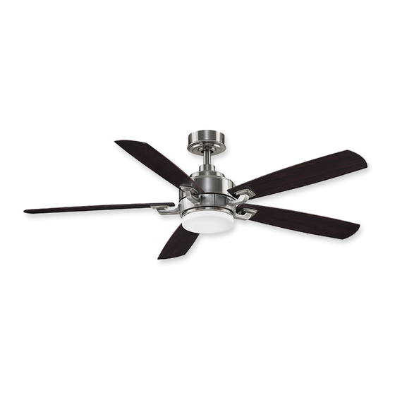
BENITO v2 CEILING FAN
Purchase Date
™
MODEL #FP8003B**
Español p. 21
Net Weight 20.95 lbs (9.50 kg)
Advertisement
Chapters
Table of Contents

Related Manuals for Fanimation BENITO v2 FP8003B Series


Summary of Contents for Fanimation BENITO v2 FP8003B Series
- Page 1 BENITO v2 CEILING FAN ™ MODEL #FP8003B** Español p. 21 ATTACH YOUR RECEIPT HERE AND REGISTER YOUR FAN AT FANIMATION.COM READ AND SAVE THESE INSTRUCTIONS Serial Number Purchase Date Net Weight 20.95 lbs (9.50 kg) Questions, problems, missing parts? Before returning to your retailer, call our customer...
- Page 2 1. LIMITED LIFETIME MOTOR WARRANTY - If any part of your fan motor fails, due to a defect in materials or workmanship during the lifetime of the original purchaser, Fanimation will provide the replacement part free of charge, when the defective fan is returned to our national service center.
-
Page 3: Table Of Contents
6. All costs of removal and reinstallation of the fan are the sole responsibility of the owner of the fan and not the store that sold the fan or Fanimation. 7. Fanimation reserves the right to modify or discontinue any product at any time and may substitute any part under this warranty. -
Page 4: Unpacking Instructions
• Blade Set accessories not designated for use with this product – Balance Kit • Light Plate Assembly by Fanimation could result in personal injury or – Bag Assembly Safety Cable property damage. • Light Wire Cap With Screw • Steel Cap Assembly •... -
Page 5: Energy Efficient Use Of Ceiling Fans
8 - 9 feet from floor to the blade for optimal down into the occupied space.Remember to adjust your airflow. Consult your Fanimation Retailer for optional thermostat when using your ceiling fan - additional energy mounting accessories. - Page 6 Electrical and Structural Requirements (Continued) Deep box with brace (Figure 3) Paired with a deep box, this hanger is meant to span CEILING JOIST between two joists and takes the place of wooden blocking. WARNING To reduce the risk of fire, electric shock, or personal injury, mount to outlet box marked acceptable for fan support of 15.9 kg (35 lbs) or less and use mounting screws provided with the outlet box.
-
Page 7: How To Assemble Your Ceiling Fan
How to Assemble Your Ceiling Fan 1. Remove the hanger ball portion from the downrod/ hanger ball assembly by loosening the set screw in the hanger ball until the ball falls freely down the downrod. Remove the pin from the downrod, then remove the Downrod hanger ball. - Page 8 How to Assemble Your Ceiling Fan (continued) 6. Reinstall the hanger ball on the downrod as follows. Route the black, white and blue wires and safety cable through the hanger ball. Position the pin through the two holes in the downrod and align the hanger ball so the pin is captured in the groove in the top of the hanger ball.
-
Page 9: How To Hang Your Ceiling Fan
How to Hang Your Ceiling Fan WARNING To avoid possible electrical shock, be sure electricity is turned off at the main fuse box before hanging. (Figure 1) NOTE: If you are not sure if the outlet box is grounded, contact a licensed electrician for advice, as it must be grounded for safe operation. - Page 10 How to Hang Your Ceiling Fan (continued) Carefully lift the fan and seat the downrod/hanger ball assembly on the hanger bracket that was just attached to the ceiling joist. Be sure the groove in the ball is lined up with tab on the hanger bracket. (Figure 4) 5.
-
Page 11: How To Wire Your Ceiling Fan
How to Wire Your Ceiling Fan NOTE: The remote unit has 32 different code combinations. To prevent possible interference from or to Receiver Unit other remote units, simply change the combination code in the remote and receiver. 1. To set the code on receiver unit, slide dip switches to the same positions as set on the remote. -
Page 12: How To Install Your Canopy Housing
How to Wire Your Ceiling Fan (continued) 4. Once the connection has been made, slide the receiver into the hanger bracket, taking care not to pinch the wires. (Figure 5) Receiver Hanger Bracket Figure 5 How to Install Your Canopy Housing NOTE: This step is applicable after the neccessary wiring is completed. -
Page 13: How To Assemble Your Light Kit Or Cap
How to Assemble Your Fan Blades (continued) 2. Secure the blade holders to the motor support using the 1/4˝-20 screws through the holes located on the side of the motor support. (Figure 2) Periodically check blade holder hardware and NOTE: Blade Holder resecure if necessary. - Page 14 How to Assemble Your Light Kit or Cap (continued) CAUTION Light Plate Assembly The light source is designed for this specific LED Kit application and can overheat if serviced by untrained personnel. If any servicing is required, the product should be returned to an authorized service facility Figure 5 for examination or repair.
-
Page 15: How To Operate Your Ceiling Fan
How to Operate Your Ceiling Fan IMPORTANT: Using a full range dimmer switch (not included) to control fan speed will damage the fan. To reduce the risk of fire or electrical shock, do not use a full range dimmer switch to control the fan speed. (Figure 1) Restore electrical power to the outlet box by turning the electricity on at the main fuse box. -
Page 16: How To Install Your Remote Control
How to Operate Your Ceiling Fan (continued) If airflow is desired in the opposite direction, turn the fan off and wait for the blades to stop turning. Slide the coupling cover up to expose the reverse switch. Then slide the reverse switch on top of motor Coupling Cover assembly to the opposite position and turn fan on again. -
Page 17: Trouble Shooting
6. Fan blades out of balance. 6. Balance blades using balance kit provided in hardware bag. 1. If possible, consider using a longer 4.NOT ENOUGH AIR downrod (not included, you can buy MOVEMENT the longer downrod from fanimation.com). -
Page 18: Parts List
Parts List Model No. FP8003B** Reference # Description Part # Hanger Bracket Assembly with Screws APGAC110RDBL Downrod/Hanger Ball Assembly ADRAC1-45D** Ceiling Canopy P8003B01** Canopy Screw Cover Assembly APPAC1101D** Motor Coupling Cover Assembly APPAC1403D** Motor Assembly AMA8003B** Blade Holder Set AP8003B13** Blade Set AP8003B15** Light Plate Assembly... -
Page 19: Exploded-View Illustration
The Benito v2 - FP8003B** ™ Exploded-View Illustration NOTE: The illustration shown is not to scale or its actual configurations may vary. - Page 20 10983 Bennett Parkway Zionsville, IN 46077 Phone: 888-567-2055 Outside U.S.: 317-733-4113 2018/01 V.01 FAX: 866-482-5215 Copyright 2018 Fanimation FANIMATION.COM...
- Page 21 VENTILADOR DE TECHO BENITO v2 ™ MODELO #FP8003B** ADJUNTE SU RECIBO AQUÍ Y REGISTRE SU VENTILADOR EN FANIMATION.COM LEA Y GUARDE ESTAS INSTRUCCIONES Número de serie Peso neto 9.50 kg (20.95 lbs) Fecha de compra Preguntas, problemas, piezas faltantes? Antes de volver a la tienda, llame a nuestro Departamento de Servicio al Cliente al 1-888-567-2055, 8 a.m.
- Page 22 Instrucciones de seguridad importantes ADVERTENCIA: Siga estas instrucciones para prevenir incendios, descargas eléctricas y lesiones personales graves. Lea el manual del propietario y la información de seguridad antes de instalar su nuevo ventilador. Observe los diagramas de ensamblaje adjuntos. Antes de llevar a cabo el mantenimiento o la limpieza de la unidad, desconecte la electricidad en el panel de servicio y bloquee los medios de desconexión del mismo para evitar que se active accidentalmente.
- Page 23 GARANTÍA LIMITADA DE POR VIDA DEL MOTOR - Si se produjera una falla en alguna de las partes del motor de su ventilador debido a un defecto en los materiales o en la fabricación durante el tiempo de vida del comprador original, Fanimation proporcionará la pieza de repuesto sin cargo una vez que el ventilador defectuoso sea devuelto a nuestro centro de servicios nacional.
-
Page 24: Instrucciones Para El Desempaque
Fanimation específicamente para el mismo. La pag-nant et/ou les accessoires spécifiquement conçus sustitución de piezas o accesorios que Fanimation no designó pour ce produit par Fanimation. La substitution de para usar con este producto podría ocasionar lesiones pièces ou d'accessoires non conçus par Fanimation... -
Page 25: Requisitos Eléctricos Y Estructurales
óptimo. Consulte en que obliga al aire cálido que se acumula cerca del techo a su tienda minorista de Fanimation para obtener bajar al espacio ocupado. No olvide ajustar el termostato accesorios de montaje opcionales. - Page 26 Requisitos eléctricos y estructurales (cont.) Uso del soporte (Figura 3) Conectado a una caja de distribución eléctrica, este colgador Vigas del techo sirve para abarcar el espacio entre dos vigas y ocupar el lugar de bloqueo de la madera. ADVERTENCIA Para reducir el riesgo de incendios, descargas eléctricas o lesiones personales, fije el ventilador a la caja de distribución eléctrica marcada como aceptable para...
- Page 27 Cómo ensamblar el ventilador de techo 1. Extraiga la pieza de la bola colgante de la unidad Pasador de la bola colgante / varilla aflojando el tornillo de presión de la bola colgante hasta que la bola se libere de la varilla. Retire el pasador del barral y Varilla luego extraiga la semiesfera.
- Page 28 Cómo ensamblar el ventilador de techo (cont.) Vuelva a colocar la semiesfera en el barral como se indica a continuación. Pase los cables de negro, blanco y azul cables y cable de soporte para techo a través de la semiesfera. Pase el pasador a través de los dos orificios en el barral y alinee la semiesfera de modo que el pasador quede atrapado en la ranura de la parte superior de la misma.
- Page 29 Cómo colgar el ventilador de techo ADVERTENCIA Para evitar una posible descarga eléctrica, asegúrese de cortar la alimentación eléctrica de la caja de fusiblesprincipal antes de colgar el ventilador. (Figura 1) PRINCIPAL CAJA DE FUSIBLES NOTA: Si no está seguro de si la caja de salida tiene conexión a tierra, pida consejo a un electricista certificado, ya que debe tener conexión a tierra para un funcionamiento seguro.
- Page 30 Cómo colgar el ventilador de techo (cont.) 4. Levante cuidadosamente el ventilador y coloque el ensamble de la bola para colgar/varilla en la abrazadera para colgar que acaba de fijar a la caja de salida. Asegúrese de que la ranura de la bola esté alineada con la lengüeta de la abrazadera para colgar.
- Page 31 Cómo realizar la instalación eléctrica del ventilador de techo (cont.) NOTA: El mando a distancia incluido en este ventilador tiene 32 combinaciones diferentes de códigos. Para Unidad del receptor evitar posibles interferencias desde o hacia otros mandos a distancia, modifique el código de combinación de su transmisor y receptor.
-
Page 32: Cómo Instalar La Carcasa De La Cubierta
Cómo realizar la instalación eléctrica del ventilador de techo (cont.) 3. Una vez realizadas las conexiones, gire los Conductor blanco Conductor verde conductores hacia arriba y, con cuidado, colóquelos del suministro Caja de salida (puesta a tierra) dentro de la caja de salida; con los conductores blancos y homologada verdes hacia un lado y los conductores negros hacia el Suministro... -
Page 33: Cómo Ensamblar Las Aspas Del Ventilador De Techo
Cómo ensamblar las aspas del ventilador de techo 1. Coloque el aspa sobre el soporte de aspas con los pilotes roscados a la vista. Asegúrese de que la parte Tornillos con cabeza de inferior del aspa se encuentre bien apoyada sobre el arandela de 3/16˝-24 (3 cada uno por aspa) soporte. -
Page 34: Cómo Ensamblar Su El Kit De Iluminación O La Tapa
Cómo ensamblar su el kit de iluminación o la tapa 1. Extraiga uno de los tres tornillos del soporte ubicado en la parte inferior de la unidad del motor. Guárdelos para después y afloje levemente los otros dos tronillos. (Figura 1) Motor Figura 1 2. - Page 35 Cómo ensamblar su el kit de iluminación o la tapa (cont.) Para su uso con el kit de iluminación (C). Asegure el vidrio en la ensamble de kit de luz girándolo en el sentido de las agujas del reloj y sin Kit de luz apretar demasiado.
- Page 36 Cómo utilizar su ventilador de techo El uso de un regulador de la intensidad completa (no incluido) para controlar la velocidad del ventilador dañará el dispositivo. Para reducir el riesgo de incendio o descarga eléctrica, no utilice dicho regulador para controlar la velocidad del ventilador.
- Page 37 Cómo utilizar su ventilador de techo (cont.) 5. Funciones del control remoto: (Figura 5) Luz LED del indicador: Velocidad del ventilador Enciende el ventilador y aumenta la velocidad. Enciende el ventilador y disminuye la velocidad. Enciende el ventilador y aumenta la velocidad. Figura 5 Temporizador de apagado automático: Pulse y tanto el ventilador y la iluminación se...
-
Page 38: Limpieza De Las Aspas
Mantenimiento El único mantenimiento necesario para el ventilador de PRECAUCIÓN techo es una limpieza periódica. No utilice solventes para limpiar el ventilador de techo. Al llevar a cabo la limpieza, use sólo un cepillo suave o un Podrían dañar el motor o las aspas y ocasionar posibles paño sin pelusas, para evitar rayar el acabado. -
Page 39: Solución De Problemas
4. NO HAY SUFICIENTE 1. Si es posible, considere el uso de un barral más largo. Por ejemplo (no incluido, usted puede comprar el MOVIMIENTO DE AIRE tiempo de la vara hacia abajo fanimation.com) -
Page 40: Lista De Piezas
Lista de piezas Modelos N .° FP8003B** Descripción Pieza # N.° N.° de Ref. Unidad del soporte de suspensión APGAC110RDBL Unidad del barral/de la semiesfera ADRAC1-45D** Capuchón de techo P8003B01** APPAC1101D** Cubierta para el tornillo del capuchón Cubierta de unión del motor APPAC1403D** Unidad del motor AMA8003B**... -
Page 41: Ilustración Del Despiece
The Benito v2 - FP8003B** ™ Ilustración del despiece NOTA La ilustración que se muestra no está hecha a escala y sucguraciónrealy/oterminación puede variar. - Page 42 10983 Bennett Parkway Zionsville, IN 46077 Llame sin cargo al (888) 567-2055 FAX (866) 482-5215 Desde fuera de los EE.UU., llame al (317) 733-4113 2018/01 V.01 Visite nuestro sitio Web en www.fanimation.com Copyright 2018 Fanimation...
Need help?
Do you have a question about the BENITO v2 FP8003B Series and is the answer not in the manual?
Questions and answers