Em-Trak B400 Series Quick Start Manual
Ais transceiver
Hide thumbs
Also See for B400 Series:
- Installation manual (3 pages) ,
- Quick start manual (2 pages) ,
- Installation and operation manual (78 pages)
Advertisement
Class B
AIS Transceiver
QUICK START GUIDE
For full instructions on how to install and use your
AIS Transceiver please refer to the product manual.
What's in the box?
AIS transceiver
Fixings
Power cable
What do I need?
Pozidriv (PZ2)
screwdriver
Allen keys (3mm, 4mm)
Surge Arrestor
Saw (for panel cut-out)
Information needed for installation:
MMSI number (9 digits):
Vessel name:
Vessel callsign:
Vessel dimensions and GNSS antenna position:
Ref C
Stern
Ref B
Ref D
Ref A + Ref B = Length in metres
Warranty card
Product CD
Product Mounting
Template
Quick Start
Guide
Mounting bracket
Data
GNSS antenna
Accessory Cable
and cable
12V/24V
power supply
Grounding wire
VHF antenna
(Connector
type: PL-259)
Drill
Antenna
Bow
Ref A
Ref C + Ref D = Beam in metres
201-0708:3
Step 1 – Install the Transceiver
Step 2 – Install the Antennas
GNSS antenna should be at least 5m (16ft)
from RADAR or satellite communication antennas.
It should also be away from the RADAR beam path
and mounted on a rigid surface.
VHF antenna should be at least
3m (10ft) from other transmitting radio,
satellite and RADAR antennas.
GNSS antenna
5m (16ft)
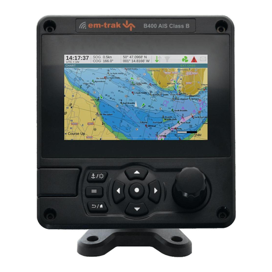
Front panel controls
Micro SD card
slot behind door
Options menu
Overhead mounted
(reverse mounting bracket)
Panel mounted
Desk mounted
VHF antenna
3m (10ft)
Navigation Status /
Screen brightness
Select
Back / Home
Function keys
(up, down, left right)
RADAR beam path
Display
Scroll wheel
(push to select)
Advertisement
Table of Contents

Subscribe to Our Youtube Channel
Related Manuals for Em-Trak B400 Series


Summary of Contents for Em-Trak B400 Series
- Page 1 201-0708:3 Step 1 – Install the Transceiver Class B AIS Transceiver QUICK START GUIDE Overhead mounted (reverse mounting bracket) For full instructions on how to install and use your AIS Transceiver please refer to the product manual. Panel mounted Desk mounted What’s in the box? Step 2 –...
- Page 2 Step 3 – Connecting the transceiver VHF antenna NOTE: Numbers and tables refer to connector pins on unit GNSS antenna Surge arrestor SIGNAL WIRE COLOUR VIN + VIN - BLACK Chassis/GND Black This product must be connected to protective earth via the earth connection point.
Need help?
Do you have a question about the B400 Series and is the answer not in the manual?
Questions and answers