Table of Contents
Advertisement
Quick Links
Advertisement
Table of Contents

Subscribe to Our Youtube Channel
Related Manuals for Mindeo FS390


Summary of Contents for Mindeo FS390
- Page 1 FS390 Fixed Image Scanner User Manual Version: FS390_UM_EN_V1.1.1...
-
Page 3: Table Of Contents
Contents Contents ..............................i Notes about structure and electric circuit design ..................v 1 Specifications ............................. 1 1-1 Technical specifications ........................ 1 1-2 Default setting for each barcode ....................3 2 Get started ............................5 2-1 Overview ............................5 2-2 Electrical interface/Pin assignment of cable connector ..............6 2-3 Typical input/output, LDO external, and DC/DC circuitries ............ - Page 4 6-17 Interleaved 2 of 5 ........................52 6-18 Industrial 2 of 5 ......................... 54 6-19 Matrix 2 of 5 ..........................55 6-20 Codabar ............................ 57 6-21 Code 128 ..........................59 6-22 UCC/EAN 128 (GS1-128) ......................61 6-23 ISBT 128 ........................... 63 6-24 Code 93 ............................
- Page 5 9 Enable & Disable “NR” ........................110 10 Barcode representing non-printable character ................111 11 ASCII table ............................ 112 12 Test symbols ..........................113 13 Return default parameters & firmware version ................118 14 Configuration alphanumeric entry barcode ..................119...
-
Page 7: Notes About Structure And Electric Circuit Design
Notes about structure and electric circuit design 1. The fixed scanner must be electrically isolated. 2. Leave sufficient space to accommodate the maximum size of the fixed scanner. -
Page 9: Specifications
1 Specifications 1-1 Technical specifications Table 1-1 Technical specifications @25 °C Dimensions Height × Width × Depth: 9.6 cm × 7.7 cm × 2.4 cm Weight 160 g (without cable) Case material Scan window material Indicator Interface Beeper Interface supported RS-232 (3.3 V TTL-level), USB, USB virtual COM Trigger mode Hand-held;... - Page 10 6.7 mil PDF417 (20 Chars) 26 mm – 116 mm 50 mm – 132 mm 1 0 mil QR (20 Chars) 11 mm – 131 mm 23 mm – 140 mm 10 mil DM (20 Chars) 11 mm – 140 mm 27 mm –...
-
Page 11: Default Setting For Each Barcode
1-2 Default setting for each barcode Table 1-2 Default setting for each symbol Read Check digit Check digit Min. code Proprietary Code type enable verification transmission length code ID code ID UPC-A √ √ √ (12) UPC-E √ √ √ UPC-E1 √... - Page 12 Read Check digit Check digit Min. code Proprietary Code type enable verification transmission length code ID code ID GS1 DataBar √ (16) Truncated GS1 DataBar √ (16) Limited GS1 DataBar √ Expanded GS1 Composite PDF417 √ MicroPDF417 DataMatrix √ QR code √...
-
Page 13: Get Started
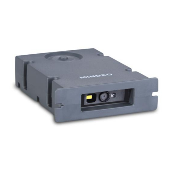
2 Get started 2-1 Overview The scanner is a CMOS imager-based (black/white) device for image capture and barcode decode. It supports reading all major 1D and 2D barcodes. Figure 2-1 Appearance of scanner ① Scan button ② Scan window... -
Page 14: Electrical Interface/Pin Assignment Of Cable Connector
2-2 Electrical interface/Pin assignment of cable connector Table 2-1 lists the pin assignments of the scanner. Pin 10 Pin 1 Figure 2-2 Electrical interface/Pin Table 2-1 Electrical interface/Pin assignment RS-232 Descriptions Pin/Signal Name Type Pin/Signal Name Type Power (5V) Power Power (5V) Power Power: +5 VDC... - Page 15 The scanner has a TTL-level RS-232 interface to communicate with a host. RTS and CTS are only used for hardware flow control and should be leaved unconnected or tied to V by 100K Ohm resistors when they are not used. The following diagram demonstrates the interconnection.
-
Page 16: Typical Input/Output, Ldo External, And Dc/Dc Circuitries
2-3 Typical input/output, LDO external, and DC/DC circuitries Table 2-2 Typical input/output, LDO external, and DC/DC circuitries Input: each input IO pin is internally pulled up by a 100K Ohm resistor (VCC=3.3V). Min. Max. -0.3V 0.7V 2.4V 3.6V Output: each output port is an open-drain pad with a 100K Ohm pull-up resistor and the maximum sink current is 100 mA (VCC=3.3V). -
Page 17: Power Management
2-4 Power management The scanner has three power modes: Operate, Idle and Standby. The Idle and Standby modes have relative lower power consumption. The following figure illustrates the state machines of the power management. Higher Power Operate ① Idle ② Standby Lower Power Figure 2-5 State machine of power management... - Page 18 The associated current draws of different power modes are listed in the following table. Table 2-3 Current draws of different power modes @ 5V, 25°C Power mode Description Current Maximum current spike seen when power is applied to Power-on I the scanner or when the scanner turns on for the first 598 mA Inrush...
-
Page 19: Installation Guide
3 Installation guide 3-1 Mounting Figure 3-1 Mounting diagram... -
Page 20: View Of Field
3-2 View of field Figure 3-2 View of fied (horizontal) - Page 21 Figure 3-2 View of fied (vertical)
-
Page 22: Installation Of Scan Window
3-3 Installation of scan window A (Distance between scan window and scanner, mm) B (Min. positive angle) 27° 26° 25° 24° 23° C (Min. negative angle) 27° 26° 25° 24° 23° A (Distance between scan window and scanner, mm) B (Min. positive angle) 22°... -
Page 23: Notes Of Timing
4 Notes of timing 4-1 Timing characteristics Table 4-1 Timing characteristics Symbol Parameter Conditions Min. Typ. Max. Unit General characteristics Low to high rise time =50pf High to low fall time =50pf Trigger timing Trigger low level hold time trig_1 Trigger high level hold time trig_h Trigger de-bounce time... -
Page 24: Operation Of Scanner
5 Operation of scanner The following cases demonstrate how a host operates an scanner quickly and easily. 5-1 Beep ① Host sends a <BEL> (0x07) character. ② After receiving <BEL> character, scanner returns a <BEL> character and an <ACK> (0x06) character, and then Scanner beeps. -
Page 25: Decode By Commands
5-4 Decode by commands ① Host sends a command (0x16, 0x4D, 0x0D, 0x30, 0x34, 0x30, 0x31, 0x44, 0x30, 0x35, 0x2E) to set Scan mode to Host. ② Then scanner responses with the received command and a <ACK>(0x06) character, and then change Scan mode to Host. -
Page 26: Parameter Menus
6 Parameter menus 6-1 Introduction This section describes the programmable parameters, to change the parameter values. 6-2 Single-parameter setting by scanning 1D barcodes 6-3 Multiple-parameter Refer to setting by scanning a QR code barcode , scan the appropriate barcodes included in this section, The new values replace the existing values. -
Page 27: Example 1: Single-Parameter Setting By Scanning 1D Barcodes
6-2 Example 1: Single-parameter setting by scanning 1D barcodes Important notes: 1. After each successful programming, the scanner will beep twice. 2. Throughout the programming barcode menus, the factory default settings are indicated with asterisks (*). Two programming modes have been provided as bellows: ❶... -
Page 28: Example 2: Multiple-Parameter Setting By Scanning A Qr Code Barcode
6-3 Example 2: Multiple-parameter setting by scanning a QR code barcode User can customize a QR code barcode to set multiple parameters. The scanner can set multiple parameters by scanning this single QR code barcode. 1. The data format of the QR code barcode is as following. Parameter set 1 Parameter set 2 Parameter set N... -
Page 29: Interface
6-4 RS-232 interface Flow control: None - The communication only uses TXD and RXD signals without any hardware or software handshaking protocol. RTS/CTS – If the scanner wants to send the barcode data to the host, it will assert the RTS signal first, and then waits for the CTS signal from the host to perform normal data communication. - Page 30 Multiple-scan setting Single-scan setting Option barcode Option Alpha. entry None RTS/CTS Flow control Two-direction flow control XON/XOFF ACK/NAK 10ms Inter-character delay 20ms 40ms 80ms 00-99 Response delay 00-99 (100ms) Baudrate 1200 2400 4800...
- Page 31 Multiple-scan setting Single-scan setting Option barcode Option Alpha. entry 9600 19200 38400 57600 115200 None Parity bit Even 8 bits Data bit 7 bits 1 bit Stop bit 2 bits...
-
Page 32: Usb Interface
6-5 USB interface USB device type: HID keyboard – By setting, the scanner is used as a USB HID keyboard emulation device. USB virtual COM – By setting, the scanner emulate a regular RS-232-based COM port. If a Microsoft Windows PC is connected to the scanner, a driver is required to install on the connected PC. The driver will use the next available COM Port number. - Page 33 Multiple-scan setting Single-scan setting Option bar code Option Alpha. entry HID keyboard HID keyboard for Apple Mac USB device type USB virtual COM Simple COM Port Emulation Turkish F Turkish Q French Italian Spanish Keyboard layout Slovak Denmark Japanese German Belgian Russian 0 ms...
- Page 34 Multiple-scan setting Single-scan setting Option bar code Option Alpha. entry 10 ms 20 ms 40 ms 60 ms Alphabetic key Numeric key Numeric keypad Alt + keypad...
-
Page 35: Scan Mode & Some Global Settings
6-6 Scan mode & some global settings Scan mode: Good-read off – The trigger (Pin - 12 TRIG) must be pulled down once to activate scanning. The scanner will stop scanning when there is a successful reading or no code is decoded after the Scan standby duration elapsed. - Page 36 Example: Group 1 set 01 or 10, Group 2 and 4 set 24 or 42. All valid settings include 00, 01, 02, 03, 04, 10, 11, 12, 13, 14, 20, 21, 22, 23, 24, 30, 31, 32, 33, 34, 40, 41, 42, 43, and 44.
- Page 37 Multiple-scan setting Single-scan setting Option barcode Option Alpha. entry Good-read off Momentary Alternate continue Scan mode Continue Time-out off Host Infrared-detecting 01-99 Scan standby duration 01-99 (4 s) 00-FF Same barcode delay time for 1D symbols 00-FF (100 ms) 00-FF Same barcode delay time for 2D symbols 00-FF...
- Page 38 Multiple-scan setting Single-scan setting Option barcode Option Alpha. entry Global min. code length for 01-99 1D symbols 01-99 00-44 Global G1-G4 string selection 00-44 Disable Element amendment Enable None Character output restraint Printable characters only Alphanumeric characters only Disable Decoder optimization Enable ASCII Character encoding system...
- Page 39 Multiple-scan setting Single-scan setting Option barcode Option Alpha. entry Enable 00-99 Idle time-out interval 00-99 (2s) Disable Sleep mode enter Enable 00-99 Standby time-out interval 00-99 (2s) 00-FF Continue scan mode time-out 00-FF (5 min)
-
Page 40: Indication
6-7 Indication Power on alert: After power-on the scanner will generate an alert signal to indicate a successful self-test. Beeper indication: After each successful reading, the scanner will beep to indicate a good barcode reading, and its beep tone duration is adjustable. Beep on BEL Character: The scanner will beep upon a <BEL>... -
Page 41: Decode Illumination Mode And Decode Aiming Pattern
6-8 Decode illumination mode and Decode aiming pattern Decode illumination mode: Enable illumination causes the scanner to turn on the illumination to aid decoding. Disable illumination to turn off illumination for the scanner during decoding. Better quality images could be obtained with illumination support. The effectiveness of the illumination decreases as the distance to the target increases. -
Page 42: Single Type Of Barcode, Multi-Symbols, And Vertical Centering Read
6-9 Single type of barcode, Multi-symbols, and Vertical centering read 1D symbols read: A global setting of 1D symbols readability. 2D symbols read: A global setting of 2D symbols readability. Multi-symbols read: By setting Enable, the scanner allows to read multiple symbols in one image. By setting Disable, the scanner will only read the symbol closest to the center area in the image. - Page 43 Multiple-scan setting Single-scan setting Option barcode Option Alpha. entry Follow respective 1D symbol setting 1D symbols read All 1D Disable All 1D Enable Follow respective 2D symbol setting All 2D Disable All 2D Enable Only PDF417 Enable 2D symbols read Only QR code Enable Only Data Matrix Enable Only MaxiCode Enable...
- Page 44 Note: The instruction of calibrating the aimer in vertical centering direction. Scan the barcode (“%initD00%”) on this page. The scanner will give three musical short beeps to indicate entering calibration mode. Press the trigger of the scanner while maintaining the distance of about 15cm between the exit window of the scanner and this paper.
-
Page 45: Dpm, Structured Append Symbols, And Mobile Screen Read
6-10 DPM, Structured append symbols, and Mobile screen read DPM format read: By setting Enable, the scanner can read 2D symbols in DPM (Direct Park Marking) format. Some barcodes in DPM format are shown below. Structured append symbols read: By setting Enable, the scanner will output data only when all Structured Append symbols have been decoded. - Page 46 Multiple-scan setting Single-scan setting Option barcode Option Alpha. entry Disable DPM format read Enable Structured append symbols Disable read Enable Disable Mobile screen read Enable...
-
Page 47: Upc-A
6-11 UPC-A Read: Format System character Data digits (10 digits) Check digit Check digit verification: The check digit is optional. Check digit trans.: By setting Enable, check digit will be transmitted. Code id setting: Code ID is a one-two-character string used to represent the symbol upon a succeeding reading. - Page 48 Multiple-scan setting Single-scan setting Option barcode Option Alpha. entry Disable Read Enable Disable Check digit verification Enable Disable Check digit trans. Enable 00-FF Code ID setting 00-FF (ASCII) <A>* 00-44 Insert group selection 00-44 None 2 digits Supplement digits 5 digits 2 or 5 digits None Truncate leading...
-
Page 49: Upc-E
6-12 UPC-E Read: Format System character “0” Data digits (6 digits) Check digit Check digit verification: The check digit is optional. Check digit trans.: By setting Enable, check digit will be transmitted. 6-11 UPC-A Code id setting: Refer to Code ID setting of 6-11 UPC-A Insertion group selection: Refer to Insertion group selection of Supplement digits:... - Page 50 Multiple-scan setting Single-scan setting Option barcode Option Alpha. entry Disable Read Enable Disable Check digit verification Enable Disable Check digit trans. Enable 00-FF Code ID setting 00-FF (ASCII) <D>* 00-44 Insert group selection 00-44 None 2 digits Supplement digits 5 digits 2 or 5 digits None Truncate leading zeros...
-
Page 51: Upc-E1
6-13 UPC-E1 Read: Format System character “1” Data digits (6 digits) Check digit Check digit verification: The check digit is optional. Check digit trans.: By setting Enable, check digit will be transmitted. 6-11 UPC-A Code id setting: Refer to Code ID setting of 6-11 UPC-A Insertion group selection: Refer to Insertion group selection of Supplement digits:... - Page 52 Multiple-scan setting Single-scan setting Option barcode Option Alpha. entry Disable Read Enable Disable Check digit verification Enable Disable Check digit trans. Enable 00-FF Code ID setting 00-FF (ASCII) <D>* 00-44 Insert group selection 00-44 None 2 digits Supplement digits 5 digits 2 or 5 digits None Expand to EAN-13...
- Page 53 6-14 EAN-13 Read: Format Data digits (12 digits) Check digit Check digit verification: The check digit is optional. Check digit trans.: By setting Enable, check digit will be transmitted. 6-11 UPC-A Code id setting: Refer to Code ID setting of 6-11 UPC-A Insertion group selection: Refer to Insertion group selection of Supplement digits:...
- Page 54 Multiple-scan setting Single-scan setting Option barcode Option Alpha. entry 00-44 Insert group selection 00-44 None 2 digits Supplement digits 5 digits 2 or 5 digits Disable ISBN/ISSN conversion Enable 00-FF ISBN/ISSN code ID setting 00-FF (ASCII) <B>*...
- Page 55 6-15 EAN-8 Read: Format Data digits (7 digits) Check digit Check digit verification: The check digit is optional. Check digit trans.: By setting Enable, check digit will be transmitted. 6-11 UPC-A Code id setting: Refer to Code ID setting of 6-11 UPC-A Insertion group selection: Refer to Insertion group selection of Supplement digits:...
- Page 56 Multiple-scan setting Single-scan setting Option barcode Option Alpha. entry Disable Read Enable Disable Check digit verification Enable Disable Check digit trans. Enable 00-FF Code ID setting 00-FF (ASCII) <C>* 00-44 Insert group selection 00-44 None 2 digits Supplement digits 5 digits 2 or 5 digits None Truncation/Expansion...
-
Page 57: Code 39 (Code 32, Trioptic Code 39)
6-16 Code 39 (Code 32, Trioptic Code 39) Read: Format Start character(*) Data digits (variable) Check digit (optional) End character(*) Check digit verification: The check digit is optional and made as the sum module 43 of the numerical value of the data digits. Check digit trans.: By setting Enable, check digit will be transmitted. - Page 58 Multiple-scan setting Single-scan setting Option barcode Option Alpha. entry Disable Read Enable Disable Check digit verification Enable Disable Check digit trans. Enable 00-99 Max. code length 00-99 00-99 Min. code length 00-99 00-FF Code ID setting 00-FF (ASCII) <M>* 00-44 Insert group selection 00-44 Standard...
- Page 59 Multiple-scan setting Single-scan setting Option barcode Option Alpha. entry Disable “*” as data character Enable Disable Convert Code 39 to Code 32 Enable Disable Code 32 prefix “A” transmission Enable Disable Trioptic Code 39 read Enable Trioptic Code 39 Disable Start/End transmission Enable...
-
Page 60: Interleaved 2 Of 5
6-17 Interleaved 2 of 5 Read: Format Data digits (variable) Check digit (optional) Check digit verification: The check digit is made as the sum module 10 of the numerical value of the data digits. There are two optional check digit algorithms: the specified Uniform Symbol Specification (USS) and the Optical Product Code Council (OPCC). - Page 61 Multiple-scan setting Single-scan setting Option barcode Option Alpha. entry Disable Read Enable Disable Check digit verification OPCC Disable Check digit trans. Enable 00-99 Max. code length 00-99 00-99 Min. code length 00-99 00-FF Code ID setting 00-FF (ASCII) <I>* 00-44 Insert group selection 00-44...
-
Page 62: Industrial 2 Of 5
6-18 Industrial 2 of 5 Read: Format Data digits (variable) 6-16 Code 39(Code 32, Trioptic Code 39) Max./Min. code length: Refer to Max./Min. code length of 6-11 UPC-A Code id setting: Refer to Code ID setting of 6-11 UPC-A Insertion group selection: Refer to Insertion group selection of Multiple-scan setting Single-scan setting Option barcode... -
Page 63: Matrix 2 Of 5
6-19 Matrix 2 of 5 Read: Format Data digits (variable) Check digit (optional) Check digit verification: The check digit is made as the sum module 10 of the numerical value of the data digits. Check digit trans.: By setting Enable, check digit will be transmitted. 6-16 Code 39(Code 32, Trioptic Code 39) Max./Min. - Page 64 Multiple-scan setting Single-scan setting Option barcode Option Alpha. entry Disable Read Enable Disable Check digit verification Enable Disable Check digit trans. Enable 00-99 Max. code length 00-99 00-99 Min. code length 00-99 00-FF Code ID setting 00-FF (ASCII) <X>* 00-44 Insert group selection 00-44...
-
Page 65: Codabar
6-20 Codabar Read: Format Start character Data digits (variable) Check digit (optional) End character Check digit verification: The check digit is made as the sum module 16 of the numerical value of the data digits. Check digit trans.: By setting Enable, check digit will be transmitted. 6-16 Code 39(Code 32, Trioptic Code 39) Max./Min. - Page 66 Multiple-scan setting Single-scan setting Option barcode Option Alpha. entry 00-FF Code ID setting 00-FF (ASCII) <N>* 00-44 Insert group selection 00-44 ABCD/ABCD abcd/abcd Start/End type ABCD/TN*E abcd/tn*E Disable Start/End transmission Enable Disable Start/End character equality Enable...
-
Page 67: Code 128
6-21 Code 128 Read: Format Data digits (variable) Check digit (optional) Check digit verification: The check digit is made as the sum module 103 of all data digits. Check digit trans.: By setting Enable, check digit will be transmitted. 6-16 Code 39(Code 32, Trioptic Code 39) Max./Min. - Page 68 Multiple-scan setting Single-scan setting Option barcode Option Alpha. entry Disable Read Enable Disable Check digit verification Enable Disable Check digit trans. Enable 00-99 Max. code length 00-99 00-99 Min. code length 00-99 00-FF Code ID setting 00-FF (ASCII) <K>* 00-44 Insert group selection 00-44 Disable...
-
Page 69: Ucc/Ean 128 (Gs1-128)
6-22 UCC/EAN 128 (GS1-128) Read: Format Data digits (variable) Check digit (optional) Check digit verification: The check digit is made as the sum module 103 of all data digits. Check digit trans.: By setting Enable, check digit will be transmitted. 6-16 Code 39(Code 32, Trioptic Code 39) Max./Min. - Page 70 Multiple-scan setting Single-scan setting Option barcode Option Alpha. entry Disable Read Enable Disable Check digit verification Enable Disable Check digit trans. Enable 00-99 Max. code length 00-99 00-99 Min. code length 00-99 00-FF Code ID setting 00-FF (ASCII) <K>* 00-44 Insert group selection 00-44 Disable...
-
Page 71: Isbt 128
6-23 ISBT 128 Read: Format “=” or “&” Data digits (variable) Check digit (optional) Check digit verification: The check digit is made as the sum module 103 of all data digits. Check digit trans.: By setting Enable, check digit will be transmitted. 6-16 Code 39(Code 32, Trioptic Code 39) Max./Min. - Page 72 Multiple-scan setting Single-scan setting Option barcode Option Alpha. entry Disable Read Enable Disable Check digit verification Enable Disable Check digit trans. Enable 00-99 Max. code length 00-99 00-99 Min. code length 00-99 00-FF Code ID setting 00-FF (ASCII) <K>* 00-44 Insert group selection 00-44...
-
Page 73: Code 93
6-24 Code 93 Read: Format Data digits (variable) 2 Check digit (optional) Check digit verification: The check digit is made as the sum module 47 of all data digits. Check digit trans.: By setting Enable, check digit will be transmitted. 6-16 Code 39(Code 32, Trioptic Code 39) Max./Min. - Page 74 Multiple-scan setting Single-scan setting Option barcode Option Alpha. entry Disable Read Enable Disable Check digit verification Enable Disable Check digit trans. Enable 00-99 Max. code length 00-99 00-99 Min. code length 00-99 00-FF Code ID setting 00-FF (ASCII) <L>* 00-44 Insert group selection 00-44...
-
Page 75: Code 11
6-25 Code 11 Read: Format Data digits (variable) Check digit 1 (optional) Check digit 2 (optional) Check digit verification: The check digit is made as the sum module 11 of all data digits. Check digit trans.: By setting Enable, check digit will be transmitted. 6-16 Code 39(Code 32, Trioptic Code 39) Max./Min. - Page 76 Multiple-scan setting Single-scan setting Option barcode Option Alpha. entry Disable Read Enable Disable Check digit verification 1 digit Disable Check digit trans. Enable 00-99 Max. code length 00-99 00-99 Min. code length 00-99 00-FF Code ID setting 00-FF (ASCII) <V>* 00-44 Insert group selection 00-44...
-
Page 77: Msi/Plessey
6-26 MSI/Plessey Read: Format Data digits (variable) Check digit 1 (optional) Check digit 2 (optional) Check digit verification: The MSI/Plessey has one or two optional check digits. There are three methods of verifying check digits, i.e. Mod10, Mod10/10 Mod11/10. The check digit1 and check digit 2 will be calculated as the sum module 10 or 11 of the data digits. - Page 78 Multiple-scan setting Single-scan setting Option barcode Option Alpha. entry Disable Read Enable Disable Check digit verification 1 digit (mod 10) Disable Check digit trans. Enable 00-99 Max. code length 00-99 00-99 Min. code length 00-99 00-FF Code ID setting 00-FF (ASCII) <O>* 00-44...
-
Page 79: Plessey
6-27 UK/Plessey Read: Format Data digits (variable) 2 Check digits (optional) Check digit verification: The UK/Plessey has one or two optional check digits. The check digit 1 and check digit 2 will be calculated as the sum module 10 or 11 of the data digits. Check digit trans.: By setting Enable, check digit will be transmitted. - Page 80 Multiple-scan setting Single-scan setting Option barcode Option Alpha. entry Disable Read Enable Disable Check digit verification Enable Disable Check digit trans. Enable 00-99 Max. code length 00-99 00-99 Min. code length 00-99 00-FF Code ID setting 00-FF (ASCII) <U>* 00-44 Insert group selection 00-44...
-
Page 81: China Post
6-28 China Post Read: Format 11 Data digits 6-16 Code 39(Code 32, Trioptic Code 39) Max./Min. code length: Refer to Max./Min. code length of 6-11 UPC-A Code id setting: Refer to Code ID setting of 6-11 UPC-A Insertion group selection: Refer to Insertion group selection of Multiple-scan setting Single-scan setting Option barcode... -
Page 82: China Finance
6-29 China Finance Note: this type of barcode is not Omni-Directionally decodable. The encodable character set includes numeric 0 to 9. Among the symbol of 0 to 9, 0 to 2, 4 and 9, 5 and 8, 6 and 7, have the symmetrical pattern;... - Page 83 Multiple-scan setting Single-scan setting Option barcode Option Alpha. entry Disable Read Enable 00-99 Max. code length 00-99 00-99 Min. code length 00-99 Disable Check digit verification Reserved Disable Enable Only 5 converted to A Leading character 5/6/7/8/9 converted to A/B/C/D/E Only 6 converted to B Only 7 converted to C Only 8 converted to D...
- Page 84 Multiple-scan setting Single-scan setting Option barcode Option Alpha. entry Assigned to 6(B) Assigned to 7(C) Assigned to 8(D) Assigned to 9(E) Assigned to 1 Assigned to 2 Assigned to 3 Assigned to 4 00-FF Code ID setting 00-FF (ASCII) <Y>* 00-44 Insert group selection 00-44...
-
Page 85: Telepen
6-30 Telepen Read: Format Start character (_) Data digits (variable) Check digit End character (z) Check digit verification: The check digit verification is optional. Check digit transmission: By setting Enable, check digit will be transmitted. 6-16 Code 39(Code 32, Trioptic Code 39) Max./Min. - Page 86 Multiple-scan setting Single-scan setting Option barcode Option Alpha. entry Disable Read Enable Disable Check digit verification Enable Disable Check digit transmission Enable 00-99 Max. code length 00-99 00-99 Min. code length 00-99 00-FF Code ID setting 00-FF 00-44 Insertion group selection 00-44 Alphanumeric Encode character set type...
-
Page 87: Gs1 Databar (Gs1 Databar Truncated)
6-31 GS1 DataBar (GS1 DataBar Truncated) GS1 DataBar Truncated is structured and encoded the same as the GS1 DataBar except that its height is reduced to a 13 modules minimum; while GS1 DataBar should have a height greater than or equal to 33 modules. -
Page 88: Gs1 Databar Limited
6-32 GS1 DataBar Limited Read: Format 16 Data digits 6-11 UPC-A Code id setting: Refer to Code ID setting of 6-11 UPC-A Insertion group selection: Refer to Insertion group selection of 6-31 GS1 DataBar (GS1 DataBar Truncated) Conversion: Refer to Conversion of Multiple-scan setting Single-scan setting Option barcode... -
Page 89: Gs1 Databar Expanded
6-33 GS1 DataBar Expanded Read: Format Data digits (variable) 6-11 UPC-A Code id setting: Refer to Code ID setting of 6-11 UPC-A Insertion group selection: Refer to Insertion group selection of 6-31 GS1 DataBar (GS1 DataBar Truncated) Conversion: Refer to Conversion of Multiple-scan setting Single-scan setting Option barcode... -
Page 90: Gs1 Composite
6-34 GS1 Composite Note: The support for this feature is available with customized firmware version. GS1 Composite symbol group consists of two components: a linear component, which encodes the item’s primary data; and an adjacent 2D composite component, which contains supplementary data. The linear component will be a traditional symbol of types: GS-128, EAN-8, EAN-13, UPC-A, UPC-E or DataBar. - Page 91 be successfully decoded to output both 1D and 2D data. GS1-128 Composite, DataBar Composite - Two versions of GS1 Composite symbol are enabled. GS1-128 Composite, DataBar Composite, UPC/EAN Composite - Three versions of GS1 Composite symbol are enabled. Multiple-scan setting Single-scan setting Option barcode Option...
-
Page 92: Pdf417
6-35 PDF417 Read: Format Data digits (variable) Multiple-scan setting Single-scan setting Option barcode Option Alpha. entry Disable Read Enable... -
Page 93: Micropdf417
6-36 MicroPDF417 Read: Format Data digits (variable) Multiple-scan setting Single-scan setting Option barcode Option Alpha. entry Disable Read Enable... -
Page 94: Qr Code
6-37 QR Code Read: Format Data digits (variable) Multiple-scan setting Single-scan setting Option barcode Option Alpha. entry Disable Read Enable... -
Page 95: Data Matrix
6-38 Data Matrix Read: Format Data digits (variable) Multiple-scan setting Single-scan setting Option barcode Option Alpha. entry Disable Read Enable... -
Page 96: Han Xin Code
6-39 Han Xin Code Note: The support for this feature is available with customized firmware version. Read: Format Data digits (variable) Multiple-scan setting Single-scan setting Option barcode Option Alpha. entry Disable Read Enable... -
Page 97: Aztec Code
6-40 Aztec Code Read: Format Data digits (variable) Multiple-scan setting Single-scan setting Option barcode Option Alpha. entry Disable Read Enable... -
Page 98: Microqr Code
6-41 MicroQR Code Note: The support for this feature is available with customized firmware version. Read: Format Data digits (variable) Multiple-scan setting Single-scan setting Option barcode Option Alpha. entry Disable Read Enable... -
Page 99: Codablock F Code
6-42 CodaBlock F Code Note: The support for this feature is available with customized firmware version. Read: Format Data digits (variable) Multiple-scan setting Single-scan setting Option barcode Option Alpha. entry Disable Read Enable... -
Page 100: Gm Code
6-43 GM code Note: The support for this feature is available with customized firmware version. Read: Format Data digits (variable) Multiple-scan setting Single-scan setting Option barcode Option Alpha. entry Disable Read Enable... -
Page 101: G1-G6 & C1-C2 & Fn1 Substitution String Setting
6-44 G1-G6 & C1-C2 & FN1 substitution string setting Format of barcode data transmission: Prefix Code name Preamble Code ID Code length Code data Code ID Postamble Suffix Suffix string setting: The <enter> key is represented indifferent ASCII when it is applied by different OS. For a Windows/DOS OS, <enter>... - Page 102 %8005H4142 %8101D02 %0407D01% Testing barcode: FN1 substitution string setting: The FN1 character (0x1D) in an UCC/EAN128 barcode, or a Code 128 barcode, or a GS1 DataBar barcode can be substituted with a defined string. Truncate leading G5 string setting: by setting, a defined leading character or string can be truncated. Also a single character can be un-defined.
- Page 103 by another defined character. The C1 and C2 replacement are applied simultaneously. Example: Replace all the “A” character in a data string to be “B” character. Original code data “1 2 3 A 5 A” Output code data “1 2 3 B 5 B” Steps: scan the following barcodes in order.
- Page 104 Multiple-scan setting Single-scan setting Option barcode Option Alpha. entry 0-22 characters 00-FF Prefix string setting None 0-22 characters 00-FF Suffix string setting <ENTER> 0D0A* 0-22 characters 00-FF Preamble string setting none 0-22 characters 00-FF Postamble string setting none 0-22 characters 00-FF Insert G1 string setting none...
- Page 105 Multiple-scan setting Single-scan setting Option barcode Option Alpha. entry 1-22 defined characters 01-7F Truncate leading G5 string setting A un-defined character <0> Defined times 01-22 Repeat of a G5 character setting Once Un-defined times (All) 1-22 defined characters 01-7F Truncate ending G6 string setting A un-defined character <0>...
-
Page 106: G1-G4 String Position & Code Id Position
6-45 G1-G4 string position & Code ID position Format of barcode data transmission Prefix Code name Preamble Code ID Code length Code data Code ID Postamble Suffix Insert G1/G2/G3/G4 string position: The scanner offers 4 positions to insert strings among the symbol. In case of the insertion position is greater than the length of the symbol, the insertion of string is not affected. -
Page 107: String Transmission
6-46 String transmission Note: The information in this chapter is closely related to 6-44 G1-G6 & C1-C2 & FN1 substitution string setting. Format of barcode data transmission Prefix Code name Preamble Code ID Code length Code data Code ID Postamble Suffix Prefix transmission: By setting Enable, prefix will be appended before the data transmitted. - Page 108 Multiple-scan setting Single-scan setting Option barcode Option Alpha. entry Disable Prefix transmission Enable Disable Suffix transmission Enable Disable Code name transmission Enable Disable Preamble transmission Enable Disable Postamble transmission Enable Disable Code ID transmission Enable Disable Code length transmission Enable Disable Case conversion Enable...
- Page 109 Multiple-scan setting Single-scan setting Option barcode Option Alpha. entry All-non-printable-character string transmission Disable with string setting Enable 01-99 Transmit the first N data characters only 01-99 Transmit the last N data characters only...
-
Page 110: Enable & Disable Configuration By Scanning Barcode
7 Enable & Disable configuration by scanning barcode Note: The setting of the below two barcodes does affect the operation of scanning the barcodes in 13 Return default parameters & firmware version. Enable configuration by scanning barcode (Default) The default status of the scanner is enabled to scan configuration barcode. Disable configuration by scanning barcode Scan the above barcode to disable scanning configuration barcode, then the scanner will not operate configuration by scanning configuration barcodes, but the data string of configuration... -
Page 111: Serial Communication Interface (Sci)
8 Serial Communication Interface (SCI) Note: The SCI programming commands can be used in place of the programming barcodes. All communication between the scanner and host occurs over the hardware interface lines using the Serial Communication Interface (SCI). The function of the SCI show as below: Maintain a bi-directional communication interface between the scanner and the host. -
Page 112: Programming Command Syntax
8-1 Programming command syntax 8-1-1 Single-parameter setting Format Prefix Parameter index Value Storage Prefix: <SYN> M <CR> (ASCII 0x16, 0x4D, 0x0D). Parameter index: Each parameter has a unique 4-digit index which is similar to the option barcode listed in 6 Parameter Menus, except that there is no leading ‘%’ and ending “M%” in the Parameter index. -
Page 113: Multiple-Parameter Setting
8-1-2 Multiple-parameter setting Format Prefix Parameter index 1 Value 1 ··· Parameter index N Value N Storage 8-1-1Single-parameter setting Prefix: Refer to Prefix of 8-1-1Single-parameter setting Parameter index 1 to Parameter index N: Refer to Parameter index of 8-1-1Single-parameter setting D/H: Refer to D/H of 8-1-1Single-parameter setting Value 1 to Value N: Refer to Value of... -
Page 114: Start Decode & Stop Decode
8-1-4 Start Decode & Stop Decode Start Decode Format <SYN> <CR> 0x16 0x54 0x0D Activate the scanner to scan barcodes when Scan Mode is Host. Stop Decode Format <SYN> <CR> 0x16 0x55 0x0D Deactivate the scanner to scan barcodes when Scan Mode is Host. 8-1-5 Return default parameters &... -
Page 115: Get Image
8-1-6 Get Image Original Image Ship Format <SYN>M<CR> %OISHP 0x16 0x4D 0x0D 0x25 0x4F 0x49 0x53 0x48 0x50 0x2E An image is taken whenever the scan operation is done. The last image is always stored in memory. The original image can be “shipped” by using the %OISHP command. Down-sampled Image Ship Format <SYN>M<CR>... -
Page 116: Examples Of Setting And Query Commands
8-2 Examples of setting and query commands The following examples illustrate how a command should be constructed and transmitted to the scanner. Example 1: Append prefix “1N” to all symbols Step 1: Set Prefix string setting to be “1N”. Look up the parameter table in 6 Parameter Menus and the ASCII table in 11 ASCII table. The target parameter index is “8001”. - Page 117 Example 2: Query current scan mode Look up the parameter table in 6 Parameter Menus and the ASCII table in 11 ASCII table. The target parameter index is “0401”. The numeral system is decimal, thus, ‘D’ is used. The value field is filled with ‘?’. Put all above parts and then append a storage indicator ‘.’...
-
Page 118: Enable & Disable "Nr
9 Enable & Disable “NR” Enable “NR” If it is enabled, while the scanner receives the STOP_DECODE command or fails to decode a barcode within the Stand-by duration time, the scanner will transmit “NR”. Disable “NR” (Default) -
Page 119: Barcode Representing Non-Printable Character
10 Barcode representing non-printable character Notes to make the following barcode: According to different barcode printing software, the method of printing following barcode is different. If using CODESOFT software, firstly read the information through “Help→Index→Code128→ Special input syntax”. Also refer to ASCII table. For example, if we wish to make “F1” barcode, select “Code128”, then select “CODE A”... -
Page 120: Ascii Table
11 ASCII table for keyboard wedge for RS-232 Null Down Left Right PgUp PgDn Home Enter Insert Ctrl+ Delete Alt+ Notes: The 2nd and the 3rd columns above are used for keyboard wedge only. “ & ‘ < > Example: ASCII “A” = “41”. -
Page 121: Test Symbols
12 Test symbols UPC-A UPC-E UPC-E1 EAN-13 ISBN/ISSN EAN-8 Code 39 Code 32 A908765439 Trioptic Code 39 (Default setting: Disable) Interleaved 2 of 5 Industrial 2 of 5 (Default setting: Disable) Matrix 2 of 5... - Page 122 Codabar Code 128 UCC/EAN 128 ISBT 128 Code 93 Code 11 (Default setting: Disable) MSI/Plessey (Default setting: Disable) UK/Plessey China Post Telepen GS1 DataBar (GS1 DataBar Truncated) GS1 DataBar Limited GS1 DataBar Expanded...
- Page 123 PDF417 12=890ab-+%xyz MicroPDF417 0239+-mdo QR code 1234567890ABCD-+()&*%^@#$!XYZ Data Matrix 123890abc-+=&*%^!mdo...
- Page 124 Aztec Code 12345678901234567890 Han Xin Code 12345678901234567890...
- Page 125 Micro QR 0123456789MINDEO CodaBlock F Code 0123456789 GM Code 0123456789MINDEO...
-
Page 126: Return Default Parameters & Firmware Version
13 Return default parameters & firmware version WARNING: Restore Factory Defaults Scan this barcode to restore the factory default values. Write to Custom Defaults Store the current scanner settings as custom defaults. Restore Custom Defaults Restore the scanner’s custom default settings. If no custom defaults were set, restore the factory default values. -
Page 127: Configuration Alphanumeric Entry Barcode
14 Configuration alphanumeric entry barcode To finish parameter setting, please scan the bar code below.
Need help?
Do you have a question about the FS390 and is the answer not in the manual?
Questions and answers