Table of Contents
Advertisement
Advertisement
Table of Contents

Related Manuals for Mindeo MS3590


Summary of Contents for Mindeo MS3590
- Page 1 MS3590 Programmable Mobile Scanner User Manual Version: MS3590_UM_EN_V1.0.3...
- Page 3 Accessory includes a Bluetooth USB adapter BA2110 which supports reliable wireless data transmission and an AC/DC adaptor for battery charge. Please charge the battery before the first time of use. The term “scanner” as used in this manual denotes the MS3590 mobile scanner unless otherwise noted.
-
Page 5: Table Of Contents
Contents Notice ..................................ii 1 Specifications ................................ 1 1-1 Technical specifications ..........................1 1-2 Default settings for each barcode ......................3 1-3 Dimensions ..............................4 1-5 Parts of the scanner ............................. 5 1-6 Parts of the Bluetooth USB adapter BA2110 ................... 6 1-7 Keys introduce .............................. - Page 6 5-4 System Information ............................ 32 5-4-1 View Memory ............................32 5-4-2 Bluetooth .............................. 32 5-4-3 Firmware Version ..........................32 6 User customized application software for MS3590 ..................33 6-1 Auto Run ..............................33 6-2 Execute ................................ 33 6-3 Download ..............................33 6-4 Installation key for deciphering encrypted file ..................
- Page 7 7-15 Code 128 ..............................64 7-16 UCC/EAN 128 ............................66 7-17 ISBT 128 ..............................68 7-18 Code 93 ..............................69 7-19 Code 11 ..............................70 7-20 MSI/Plessey .............................. 72 7-21 UK/Plessey ............................... 74 7-22 China Post ..............................75 7-23 GS1 DataBar (GS1 DataBar Truncated) ....................76 7-24 GS1 DataBar Limited ..........................
-
Page 8: Specifications
1 Specifications 1-1 Technical specifications Table 1-1 Technical specifications of the scanner 16 MB for out of range batch/data batch mode: 1,118,480 barcodes (each barcode is Data storage of 15 bytes); 96 MB for U Disk mode: 1,509,949,440 barcodes (each barcode is of 15 bytes). 2.5GHz (ISM band), Bluetooth V2.1+EDR Radio link Working range... - Page 9 Input Voltage 4.75V – 5.25V Operating current 5mA (sleeping); 350mA (scanning); 360mA (transmitting) Standby time Over 7 days Operating time 5.5 hours 3.5mil Code128 ( 9 chars): 1.5cm – 3.5cm 5mil Code39 (20 chars): 0.8cm – 5.5cm 13mil UPC (12 chars): 0.7cm – 16.5cm Decoding depth 20mil Code39 ( 5 chars): 3.5cm –...
-
Page 10: Default Settings For Each Barcode
1-2 Default settings for each barcode Table 1-3 Default setting for each barcode Min. code Read Check digit Check digit Proprietary Code type length enable verification transmission code ID code ID UPC-A √ √ √ (12) UPC-E √ √ √ UPC-E1 √... -
Page 11: Dimensions
Min. code Read Check digit Check digit Proprietary Code type length enable verification transmission code ID code ID MicroPDF417 √ DataMatrix √ QR code √ Han Xin Code √ Aztec Code √ Note: The settings for ISBN/ISSN and EAN-13 must be the same except the code ID. Fixed-length barcodes. -
Page 12: Parts Of The Scanner
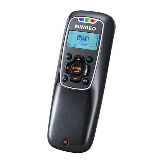
1-5 Parts of the scanner Front view Back view Top view Bottom view Figure 1-3 Parts of the scanner ○ 1 Blue LED (Bluetooth power); Green LED (Decode success); Red LED (Charging indicator) ○ 2 LCD ○ 3 Left soft key ○... -
Page 13: Parts Of The Bluetooth Usb Adapter Ba2110
1-6 Parts of the Bluetooth USB adapter BA2110 Figure 1-4 Parts of the Bluetooth USB adapter BA2110 ○ 19 Reset/Firmware upgrade key ○ 20 Green LED (Power/Data transmission) -
Page 14: Keys Introduce
1-7 Keys introduce Operations, such as scrolling and selecting menus, moving a cursor, or scanning a barcode, are controlled by trigger keys and stroke keys. Table 1-4 Key functions Key/Action/Feature Description Part Position Functionalities are identified by the screen display. In general, ○... -
Page 15: Introduction To Installation
2 Introduction to installation 2-1 Installing a USB HID keyboard wired scanner Note: The default interface of the scanner is BT HID Keyboard. Please change the interface to USB HID 5-2 Data Transfer Keyboard (See “ ”). Refer to Figure 2-1, plug one end of the USB cable to the scanner. Plug the other end into the USB port of the computer. -
Page 16: Attaching The Neck/Wrist Strap
2-3 Attaching the neck/wrist strap Note: The neck/wrist strap protects the scanner from being damaged as a result of it being dropped by mistake during movement. Refer to Figure 2-2, remove the 3 screws from the battery cover (one at a time). Attach the neck/wrist strap by hanging the strap ring around the raised part at the corner. -
Page 17: Getting Started
3 Getting started 3-1 Power on/off scanner Power on scanner: Press the Power/Sleep key (see Parts of the scanner) for two seconds. Power off scanner: Press the Power/Sleep key (see Parts of the scanner) for two seconds. 3-2 Charge battery Please charge the battery before the first time of use. -
Page 18: Introduction To Lcd Display
4 Introduction to LCD display 4-1 LCD display icons Notes: 1- The LCD screen is designed to display barcode scanning, Bluetooth network establishing, data transfer, system setting and other information. 2- The display area is 64 dots (V) by 128 dots (H). The backlight will be switched off automatically if time of no operation exceeds a programmable duration (see System SettingBacklight Timeout). -
Page 19: Lcd Display Menu
4-2 LCD display menu The Home menu consists of five items, which are described in details in the following chapters. Table 4-2 depicts the hierarchy chart of the LCD display menu. Table 4-2 LCD display menu Menu Hierarchy chart 1. Good-read off * Scan Mode 2. - Page 20 Menu Hierarchy chart 1.Disable* Out of Range 2.Enable Auto 1.Disable* Bluetooth* Reconnection 2.Enable Inter-character delay BA2110 Connect USB HID Time Keyboard USB Virtual Create New File Empty File Data Transfer U-Disk List Files Delete File Format Send Batch Data 1.Bluetooth* Interface 2.USB HID Keyboard 3.USB Virtual COM...
- Page 21 Menu Hierarchy chart 1. USA* BT HID 2. French Keyboard * 3..Bluetooth BT SPP Slave BT SPP Master BA2110 1. USA* USB HID 2. French keyboard 3..1. English * Language 2. Chinese 1. Low 2. Middle* 1.
- Page 22 Menu Hierarchy chart A ut o R un Execute Application D ow nl oad I nst al l at i on K ey Ver i f i cat i on C ode Note: Items that are labeled ‘*’ are default selections.
-
Page 23: Operations Of The Scanner
5 Operations of the scanner Note: 1. Please establish a Bluetooth network and hold the scanner in the range of the network before the first time of scanning barcodes (See chapters of Configure Bluetooth HID keyboard profile communication, Configure Bluetooth SPP slave profile communication, and Configure Bluetooth SPP master profile communication). -
Page 24: Quantity Enter
5-1-3 Quantity Enter User can disable the Quantity Enter and select Repeat Output mode or Output Quantity mode. When Quantity Enter is enabled, user can set the number (0 to 9999) of barcode transmissions. For example, a barcode “123456789” is read. When user select Repeat Output mode, Five “123456789” will be received by the host, given that the quantity is 5. -
Page 25: Add Date
5-1-5 Add Date The data information can be added as an appendix to a barcode by enabling the Add Date. For example: When Add Date is enabled, a barcode “123456789” is read in 25.05.2012, “123456789, 25.05.2012” will be received by the host。 When Add Time and Add Date is enabled, a barcode “123456789”... -
Page 26: Avoid Duplication
to the flash disk. 5-1-8 Avoid Duplication When user scans the barcode, the scanner retrieves the database for a match in the meantime. If the barcode does not exist in the database, the barcode will be recorded into the database file, sent out or stored in USB Disk. -
Page 27: Transfer Confirm
Caution: Empty and Delete operations are not undoable. It is strongly recommended to back up the data before empty or delete operation. Empty/Delete Files If the U-disk is almost full, occupied room can be released by emptying/deleting some files. A target file is protected by system and prevented from being deleting. In this case, the file that is wanted to be deleted should be deselected and then deleted. -
Page 28: Data Transfer
5-2 Data Transfer 5-2-1 Bluetooth See System Setting - Bluetooth for instructions to establish a Bluetooth network. Three options are listed below. Out of range batch- The scanner starts storing barcode data when it loses its connection to a remote host (for example, when a user holding the scanner walks out of range). -
Page 29: Data Batch
Options Menu Note: Press Left Soft Key to popup this menu. Caution: Empty and Delete operations are not undoable. It is strongly recommended to back up the data before empty or delete operation. Empty/Delete Files If the U-disk is almost full, occupied room can be released by emptying/deleting some files. A target file is protected by system and prevented from being deleting. -
Page 30: System Setting
5-3 System Setting 5-3-1 Bluetooth Ⅰ Bluetooth functionalities The scanner can be configured to send data to a PC/Notebook/PDA/other instrument which has an integrated Bluetooth module or is connected with an external Bluetooth USB adapter. A diagram of Bluetooth functionalities and a table of various Bluetooth profiles are shown below, respectively: Figure 5-1. - Page 31 Alternatively, you may go to Control Panel->Bluetooth Device. Step3. Click Add to search devices nearby. Step4. Click to select “My device is set up and ready to be found” and click Next. Step5. It takes a few seconds for the Wizard to search devices. The scanner will appear with its serial number as the device name.
- Page 32 Step7. The scanner promotes the user to accept the connection request. Press Left Soft Key to accept. Step8. Enter a passkey which is exactly the same as that entered from the PC. Use Navigation Key to move the cursor, Scan/Select Key to select number(s), Right Software Key to delete selected number. Finally press Left Software Key to continue.
- Page 33 Step12. Run the desired application, such as a Notepad and scan barcodes to check data transmission. Ⅲ Configure Bluetooth SPP slave profile communication Note: Make sure the Bluetooth module of the scanner is powered on (blue LED is on) and the selected profile is System SettingBluetoothBT SPP Slave.
- Page 34 Step11. Now the target scanner will be listed as shown below. Step12. Run a Serial Port Tool, e.g. HyperTerminal on your computer. This step guarantees the scanner to complete establishing Bluetooth communication. And then scan a barcode to confirm the success of data transmission.
- Page 35 Ⅳ Configure Bluetooth SPP master profile communication Note: Make sure the Bluetooth module of the scanner is powered on (blue LED is on) and the selected profile is System SettingBluetoothBT SPP Master. Step1. Press Left Soft Key to the window below. If the scanner has no connection record, it will show the indication”...
- Page 36 Step6. The Bluetooth device connected to the scanner is labeled √. Step7. If you want to disconnect the Bluetooth device connected successfully before, you can press Scan/Select Key to disconnect it. Ⅴ Configure Bluetooth USB adapter BA2110 Notes: 1. BA2110 is provided by the manufacturer to support reliable wireless data transmission and is advised in applications whereas unacknowledged communication is unacceptable.
-
Page 37: Usb Hid Keyboard
Step2. Press Left Soft Key to the window below for searching. Step3. Wait for about 20 seconds and then BA2110 list will be shown. Step4. Use Navigation Key to move the cursor and press Scan/Select Key to connect with BA2110. Step5. -
Page 38: Vibrator
5-3-5 Vibrator This option is used to turn on/off the vibrator indicator of a good read. 5-3-6 Backlight timeout The scanner will switch off the backlight if time of no operation exceeds Backlight timeout. 5-3-7 Sleep timeout The scanner will enter sleep mode if time of no operation exceeds Sleeping timeout. User can set the scanner to sleep mode by press Power/Sleep key (see Enter/exit sleep mode and power on/off Bluetooth). -
Page 39: System Information
customized software development). When this option is enabled, system password is required when switching from user application state back to system state. If the user download the user customized application software, and enable the boot settings, the system is run directly to the user's application when switched on. When user keep pressing the right soft key during system booting stage, the system password is required before entering the system state. -
Page 40: User Customized Application Software For Ms3590
Enter into this menu to download application by MS3 SDK; Step1. Power on the scanner, enter into the menu:Application->Download; Step2. Make sure of connecting the PC and MS3590 well with USB cable; Step3. Clicking on the button in the toolbar of MS3 SDK to perform download BIN file or ENP file to the scanner;... -
Page 41: Installation Key For Deciphering Encrypted File
6-4 Installation key for deciphering encrypted file The scanner provides setting of user customized application software installation key, which use to decipher a secret BIN file ( ENP file) .Enter into this menu to download Installation key by MS3 SDK (Click Download->... -
Page 42: Barcode Programming Instructions
7 Barcode programming instructions 7-1 Single-parameter setting by scanning 1D barcodes Important notes: 1. During the process of programming, LED is lighting to indicate the programming correctness. LED will go off if any incorrect programming operation performed. 2. After each successful programming, LED will go off and the scanner will beep twice. 3. -
Page 43: Decode Illumination And Decode Aiming Pattern
7-2 Decode illumination and decode aiming pattern Decode illumination mode: Enable illumination causes the scanner to turn on the illumination to aid decoding. Disable illumination to turn off illumination for the scanner during decoding. Better quality images could be obtained with illumination support. The effectiveness of the illumination decreases as the distance to the target increases. -
Page 44: Dpm, Multiple Symbols, Structured Append, Etc. Read Setting
7-3 DPM, Multiple symbols, Structured append, etc. read setting 2D symbols read: A global setting of 2D symbols readability. DPM format read: By setting Enable, the scanner can read 2D symbols in DPM (Direct Park Marking) format. Some barcodes in DPM format are shown below. Multiple symbols &... - Page 45 vertical direction. However, the scanner will read either one of two barcodes which are positioned horizontally. See example below.
- Page 46 Multiple-scan setting Single-scan setting Option barcode Option Alpha. entry Follow respective 2D symbol setting All 2D OFF All 2D ON Only PDF417 ON 2D symbols read Only QR code ON Only Data Matrix Only MaxiCode ON Only Aztec Code Only Han Xin Code Disable DPM format read Enable...
- Page 47 Note: The instruction of calibrating the aimer in vertical centering direction. Scan the barcode on this page. The scanner will give three musical short beeps to indicate entering calibration mode. Press the trigger of the scanner while maintaining the distance of about 15cm between the exit window of the scanner and this paper.
-
Page 48: Global Settings
7-4 Global settings Scanning mode: Good-read off-The trigger button must be pressed once to activate scanning. The light source of scanner stops scanning when there is a successful reading or no code is decoded after the Stand-by duration elapsed. Momentary-The trigger button acts as a switch. Press button to activate scanning and release button to stop scanning. - Page 49 Decoder optimization: If it is enabled, the scanner will optimize the decoder with error correction. This function is not effective for all types of barcodes. Data output delay in continue-scan mode: If it is enabled, in the continue-scan mode, the scanner can store the data while continue-scanning.
- Page 50 Multiple-scan setting Single-scan setting Option barcode Option Alpha. entry Good-read off Scanning mode Momentary Continue 01-99 Standby duration 01-99 (second) 00-FF Same barcode delay time 00-FF (50ms) 00-09 Double confirm 00-09 (00: no ) Global max. code length for 1D 04-99 symbol 04-99...
- Page 51 Multiple-scan setting Single-scan setting Option barcode Option Alpha. entry Enable Data output delay in 00-FF 00-99 (100ms) continue-scan mode FF (Never) ASCII Character encoding system UTF-8 Windows-1251 Decode-data transfer type Serial in USB HID mode Parallel...
-
Page 52: Upc-A
7-5 UPC-A Read: Format System character Data digits (10 digits) Check digit Check digit verification: The check digit is optional. Check digit trans.: By setting Enable, check digit will be transmitted. Code ID setting: Code ID is a one-or-two-character string used to represent the symbol upon a succeeding reading. - Page 53 Multiple-scan setting Single-scan setting Option barcode Option Alpha. entry Disable Read Enable Disable Check digit verification Enable Disable Check digit trans. Enable 00-FF Code ID setting 00-FF (ASCII) <A>* 00-66 Insert group selection 00-66 None 2 digits Supplement digits 5 digits 2 or 5 digits None Truncate leading zeros...
-
Page 54: Upc-E
7-6 UPC-E Read: Format System character “0” Data digits (6 digits) Check digits Check digit verification: The check digit is optional and made as the sum of the numerical value of the data digits. Check digit trans.: By setting Enable, check digit will be transmitted. 7-5 UPC-A Code ID setting: Refer to Code ID setting of “... - Page 55 Multiple-scan setting Single-scan setting Option barcode Option Alpha. entry Disable Read Enable Disable Check digit verification Enable Disable Check digit trans. Enable 00-FF Code ID setting 00-FF (ASCII) <D>* 00-66 Insert group selection 00-66 None 2 digits Supplement digits 5 digits 2 or 5 digits None Truncate leading zeros...
-
Page 56: Upc-E1
7-7 UPC-E1 Read: Format Leading zero “1” Following 5 data digits Check digits Check digit verification: The check digit is optional and made as the sum of the numerical value of the data digits. Check digit trans.: By setting Enable, check digit will be transmitted. 7-5 UPC-A Code ID setting: Refer to Code ID setting of “... - Page 57 Multiple-scan setting Single-scan setting Option barcode Option Alpha. entry Disable Read Enable Disable Check digit verification Enable Disable Check digit trans. Enable 00-FF Code ID setting 00-FF (ASCII) <D>* 00-66 Insert group selection 00-66 None 2 digits Supplement digits 5 digits 2 or 5 digits None Truncate leading zeros...
-
Page 58: Isbn/Issn)
7-8 EAN-13 (ISBN/ISSN) Read: Format Data digits (12 digits) Check digit Check digit verification: The check digit is optional and made as the sum of the numerical value of the data digits. Check digit transmission: By setting Enable, check digit will be transmitted. 7-5 UPC-A EAN-13 code ID setting: Refer to Code ID setting of “... - Page 59 Multiple-scan setting Single-scan setting Option barcode Option Alpha. entry Disable Read Enable Disable Check digit verification Enable Disable Check digit transmission Enable 00-FF 00-FF EAN-13 code ID setting (ASCII) <A>* 00-66 Insert group selection 00-66 None 2 digits Supplement digits 5 digits 2 or 5 digits Disable...
-
Page 60: Ean-8
7-9 EAN-8 Read: Format Data digits (7 digits) Check digit Check digit verification: The check digit is optional and made as the sum of the numerical value of the data digits. Check digit trans.: By setting Enable, check digit will be transmitted. 7-5 UPC-A Code ID setting: Refer to Code ID setting of “... - Page 61 Multiple-scan setting Single-scan setting Option barcode Option Alpha. entry Disable Read Enable Disable Check digit verification Enable Disable Check digit trans. Enable 00-FF Code ID setting 00-FF (ASCII) <C>* 00-66 Insert group selection 00-66 None 2 digits Supplement digits 5 digits 2 or 5 digits None Truncation/Expansion...
-
Page 62: Code 39 (Code 32, Trioptic Code 39)
7-10 Code 39 (Code 32, Trioptic Code 39) Read: Format ⋆ Data digits (variable) Check digit (optional) ⋆ Check digit verification: The check digit is optional and made as the sum module 43 of the numerical value of the data digits. Check digit transmission: By setting Enable, check digit will be transmitted. - Page 63 Multiple-scan setting Single-scan setting Option barcode Option Alpha. entry Disable Read Enable Disable Check digit verification Enable Disable Check digit transmission Enable 00-99 Max. code length 00-99 00-99 Min. code length 00-99 00-FF Code ID setting 00-FF (ASCII) <M>* 00-66 Insert group selection 00-66 Standard...
- Page 64 Multiple-scan setting Single-scan setting Option barcode Option Alpha. entry Enable Code 32 Prefix “A” Disable transmission Enable Disable Trioptic Code 39 read Enable Trioptic Code 39 Start/End Disable transmission Enable...
-
Page 65: Interleaved 2 Of 5
7-11 Interleaved 2 of 5 Read: Format Data digits (Variable) Check digit (optional) Check digit verification: The check digit is made as the sum module 10 of the numerical values of all data digits. There are two optional check digit algorithms: the specified Uniform Symbol Specification (USS) and the Optical Product Code Council (OPCC). - Page 66 Multiple-scan setting Single-scan setting Option barcode Option Alpha. entry Disable Read Enable Disable Check digit verification OPCC Disable Check digit transmission Enable 00-99 Max. code length 00-99 00-99 Min. code length 00-99 00-FF Code ID setting 00-FF (ASCII) <I>* 00-66 Insert group selection 00-66...
-
Page 67: Industrial 2 Of 5 (Discrete 2 Of 5)
7-12 Industrial 2 of 5 (Discrete 2 of 5) Read: Format Data digits (variable) 7-10 Code 39 Max./Min. code length: Refer to Max./Min. code length of “ ”. 7-5 UPC-A Code ID setting: Refer to Code ID setting of “ ”. -
Page 68: Matrix 2 Of 5
7-13 Matrix 2 of 5 Read: Format Data digits (variable) Check digit (optional) Check digit verification: The check digit is made as the sum module 10 of the numerical values of all data digits. Check digit transmission: By setting Enable, check digit will be transmitted. 7-10 Code 39 Max./Min. -
Page 69: Codabar
7-14 Codabar Read: Format Start Data digits (variable) Check digit (optional) Check digit verification: The check digit is made as the sum module 16 of the numerical values of all data digits. Check digit transmission: By setting Enable, check digit will be transmitted. 7-10 Code 39 Max./Min. - Page 70 Multiple-scan setting Single-scan setting Option barcode Option Alpha. entry ABCD/ABCD abcd/abcd Start/End type ABCD/TN⋆E abcd/tn⋆e Disable Start/End transmission Enable Disable Start/End character equality Enable...
-
Page 71: Code 128
7-15 Code 128 Read: Format Data digits (variable) Check digit (optional) Check digit verification: The check digit is made as the sum module 103 of all data digits. Check digit transmission: By setting Enable, check digit will be transmitted. 7-10 Code 39 Max./Min. - Page 72 Multiple-scan setting Single-scan setting Option barcode Option Alpha. entry Disable Read Enable Disable Check digit verification Enable Disable Check digit transmission Reserved 00-99 Max. code length 00-99 00-99 Min. code length 00-99 00-FF Code ID setting 00-FF (ASCII) <K>* 00-66 Insert group selection 00-66 Disable...
-
Page 73: Ucc/Ean 128
7-16 UCC/EAN 128 Read: Format Data digits (variable) Check digit (optional) Check digit verification: The check digit is made as the sum module 103 of all data digits. Check digit transmission: By setting Enable, check digit will be transmitted. 7-10 Code 39 Max. - Page 74 Multiple-scan setting Single-scan setting Option barcode Option Alpha. entry Read Disable Enable Check digit verification Disable Enable Check digit transmission Disable Reserved Max. code length 00-99 00-99 Min. code length 00-99 00-99 Code ID setting 00-FF 00-FF (ASCII) <K>* Insert group selection 00-66 00-66 Disable...
-
Page 75: Isbt 128
7-17 ISBT 128 Read: Format “=” or “&” Data digits (variable) Check digit (optional) Check digit verification: The check digit is made as the sum module 103 of all data digits. Check digit transmission: By setting Enable, check digit will be transmitted. 7-10 Code 39 Max./Min. -
Page 76: Code 93
7-18 Code 93 Read: Format Data digits (variable) 2 check digits (optional) Check digit verification: The check digit is made as the sum module 47 of the numerical values of all data digits. Check digit transmission: By setting Enable, check digit will be transmitted. 7-10 Code 39 Max./Min. - Page 77 7-19 Code 11 Read: Format Data digits (variable) Check digit 1 (optional ) Check digit 2 (optional) Check digit verification: The check digit is presented as the sum module 11 of all data digits. Check digit transmission: By setting Enable, check digit 1 and check digit 2 will be transmitted upon your selected check digit verification method.
- Page 78 Multiple-scan setting Single-scan setting Option barcode Option Alpha. entry Disable Read Enable Disable One digit Check digit verification Reserved Reserved Disable Check digit transmission Enable 00-99 Max. code length 00-99 00-99 Min. code length 00-99 00-FF Code ID setting 00-FF (ASCII) <V>* 00-66...
-
Page 79: Msi/Plessey
7-20 MSI/Plessey Read: Format Data digits (variable) Check digit 1 (optional) Check digit 2 (optional) Check digit verification: The MSI/Plessey has one or two optional check digits. There are three methods of verifying check digits, i.e. Mod10, Mod10/10 and Mod 11/10. The check digit 1 and check digit 2 will be calculated as the sum module 10 or 11 of the data digits. - Page 80 Multiple-scan setting Single-scan setting Option barcode Option Alpha. entry Disable Read Enable Disable 1 digit (mod Check digit verification Reserved Reserved Disable Check digit transmission Enable 00-99 Max. code length 00-99 00-99 Min. code length 00-99 00-FF Code ID setting 00-FF (ASCII) <O>*...
-
Page 81: Uk/Plessey
7-21 UK/Plessey Read: Format Data digits (variable) 2 check digits (optional) Check digit verification: The UK/Plessey has one or two optional check digits. The check digit 1 and check digit 2 will be calculated as the sum module 10 or 11 of the data digits. Check digit transmission: By setting Enable, check digit will be transmitted. -
Page 82: China Post
7-22 China Post Read: Format 11 Data digits 7-10 Code 39 Max. /Min. code length: Refer to Max./Min. code length of “ ”. The code length of China Post is 11. 7-5 UPC-A Code ID setting: Refer to Code ID setting of “ ”. -
Page 83: Gs1 Databar (Gs1 Databar Truncated)
7-23 GS1 DataBar (GS1 DataBar Truncated) GS1 DataBar Truncated is structured and encoded the same as the standard GS1 DataBar format, except its height is reduced to a 13 modules minimum; while GS1 DataBar should have a height greater than or equal to 33 modules. Read: Format 16 Data digits... -
Page 84: Gs1 Databar Limited
7-24 GS1 DataBar Limited Read: Format 16 Data digits 7-5 UPC-A Code ID setting: Refer to Code ID setting of “ ”. 7-5 UPC-A Insertion group selection: Refer to Insertion group selection of “ ”. Conversion: Refer to Conversion of GS1 DataBar (GS1 DataBar Truncated). Multiple-scan setting Single-scan setting Option barcode... -
Page 85: Gs1 Databar Expanded
7-25 GS1 DataBar Expanded Read: Format Data characters (variable) 7-5 UPC-A Code ID setting: Refer to Code ID setting of “ ”. 7-5 UPC-A Insertion group selection: Refer to Insertion group selection of “ ”. Conversion: UCC/EAN 128- Refer to Code ID transmission of String transmission, ]Cm will be identified as AIM ID. Multiple-scan setting Single-scan setting Option barcode... -
Page 86: China Finance
7-26 China Finance Note: This type of barcode is not Omni-directionally decodable. The encodable character set includes numeric 0 to 9. Among the symbol of 0 to 9, 0 and 2, 4 and 9, 5 and 8, 6 and 7, have the symmetrical pattern;... - Page 87 Multiple-scan setting Single-scan setting Option barcode Option Alpha. entry Only 7 converted to C Only 8 converted to D Only 9 converted to E Disable Assigned to 0 Assigned to 5(A) Assigned to 6(B) Assigned to 7(C) Leading character assignment Assigned to 8(D) Assigned to 9(E) Assigned to 1...
-
Page 88: Pdf417
7-27 PDF417 Read: Format Data characters (variable) Multiple-scan setting Single-scan setting Option barcode Option Alpha. entry Disable Read Enable... -
Page 89: Micropdf417
7-28 MicroPDF417 Read: Format Data characters (variable) Multiple-scan setting Single-scan setting Option barcode Option Alpha. entry Disable Read Enable... -
Page 90: Qr Code
7-29 QR Code Read: Format Data characters (variable) Multiple-scan setting Single-scan setting Option barcode Option Alpha. entry Disable Read Enable... -
Page 91: Data Matrix
7-30 Data Matrix Read: Format Data characters (variable) Multiple-scan setting Single-scan setting Option barcode Option Alpha. entry Disable Read Enable... -
Page 92: Han Xin Code
7-31 Han Xin Code Read: Format Data characters (variable) Multiple-scan setting Single-scan setting Option barcode Option Alpha. entry Disable Read Enable... -
Page 93: Aztec Code
7-32 Aztec Code Read: Format Data characters (variable) Multiple-scan setting Single-scan setting Option barcode Option Alpha. entry Disable Read Enable... -
Page 94: G1-G6 & C1-C3 & Fn1 Substitution String Setting
7-33 G1-G6 & C1-C3 & FN1 substitution string setting Format of barcode data transmission Prefix Code name Preamble Code ID Code length Code data Code ID Postamble Suffix Suffix string setting: The <enter > key is represented in different ASCII when it is applied by different OS. For a Windows/DOS OS, <enter>... - Page 95 FN1 substitution string setting: The FN1 character (0x1D) in an UCC/EAN128 barcode, or a Code 128 barcode, or a GS1 DataBar barcode can be substituted with a defined string. Truncate leading G5 string setting: By setting, a defined leading character or string can be truncated. Also a single character can be un-defined.
- Page 96 Testing barcode: Multiple characters C3 replacement: By setting, a number of defined characters in the data string can be replaced by other defined characters. The maximum number of characters to replace is 11. Example: Replace all the “A” character in a data string with “B” character; replace “C” with “D”; replace “E”...
- Page 97 Multiple-scan setting Single-scan setting Option barcode Option Alpha. Entry Prefix string setting 0-22 characters 00-FF None 0-22 characters 00-FF Suffix string setting <ENTER> 0D0A* 0-22 characters 00-FF Preamble string setting None 0-22 characters 00-FF Postamble string setting None 0-22 characters 00-FF Insert G1 string setting None...
- Page 98 Multiple-scan setting Single-scan setting Option barcode Option Alpha. Entry Once Repeat of a G5 character setting Defined times 01-22 Un-defined times (All) A un-defined character Truncate ending G6 string setting 1-22 defined 01-7F characters <0> Once Repeat of a G6 character setting Defined times 01-22...
-
Page 99: G1-G4 String Position & Code Id Position
7-34 G1-G4 string position & Code ID position Format of barcode data transmission Prefix Code name Preamble Code ID Code length Code data Code ID Postamble Suffix Insert G1/G2/G3/G4 string position: The scanner offers 4 positions to insert strings among the symbol. In case of the insertion position is greater than the length of the symbol, the insertion of string is not effective. -
Page 100: String Transmission
7-35 String transmission Note: The information in this chapter is closely related to the chapter of String setting. Format of barcode data transmission Prefix Code name Preamble Code ID Code length Code data Code ID Postamble Suffix Prefix transmission: By setting Enable, prefix will be appended before the data transmitted. Suffix transmission: By setting Enable, suffix will be appended after the data is transmitted. - Page 101 Multiple-scan setting Single-scan setting Option barcode Option Alpha. entry Prefix transmission Disable Enable Disable Suffix transmission Enable Disable Code name transmission Enable Disable Preamble transmission Enable Postamble transmission Disable Enable Disable Code ID transmission Proprietary ID AIM ID Code length transmission Disable Enable Disable...
- Page 102 Multiple-scan setting Single-scan setting Option barcode Option Alpha. entry transmission Keyboard wedge/USB RS-232 Keyboard wedge / USB / RS-232 All-non-printable-character Disable string transmission with string setting Enable Transmit the first N data characters only 01-99 Transmit the last N data characters only 01-99...
-
Page 103: Test Chart
8 Test Chart UPC-A UPC-E UPC-E1 EAN-8 EAN-13 Code 39 Code 32 A908765439 Code 128 Interleaved 2 of 5 Industrial 2 of 5 (Default setting: Read disable) Matrix 2 of 5 Code 93... - Page 104 UCC/EAN 128 ISBT 128 Code 11 (Default setting: Read disable) MSI/Plessey (Default setting: Read disable) Codabar UK/Plessey ISBN/ISSN China Post GS1 DataBar (GS1 DataBar Truncated) GS1 DataBar Limited GS1 DataBar Expanded...
- Page 105 PDF417 12=890ab-+%xyz MicroPDF417 23+-mdo QR code 1234567890ABCD-+()&*%^@#$!XYZ Data Matrix 123890abc-+=&*%^!mdo Aztec Code 12345678901234567890 Han Xin Code 12345678901234567890...
-
Page 106: Ascii Table
9 ASCII Table for keyboard wedge for RS-232 Null Down Left Right PgUp PgDn Home Enter Insert Ctrl+ Delete Alt+ Notes: The 2nd and the 3rd columns above are used for keyboard wedge only. “ & ‘ < > Example: ASCII “A” = “41”. -
Page 107: Barcode Representing Non-Printable Character
10 Barcode representing non-printable character Notes to make the following barcode: 1. According to different barcode printing software, the method of printing following barcode is different. 2. If using CODESOFT software, firstly read the information through “Help→Index→Code128→Special input syntax”. Also refer to ASCII table. For example, if we wish to make “F1” barcode, select “code128”, then select “CODE A”... -
Page 108: Configuration Alphanumeric Entry Barcode
11 Configuration alphanumeric entry barcode... - Page 109 FCC STATEMENT 1. This device complies with Part 15 of the FCC Rules. Operation is subject to the following two conditions: (1) This device may not cause harmful interference. (2) This device must accept any interference received, including interference that may cause undesired operation.
Need help?
Do you have a question about the MS3590 and is the answer not in the manual?
Questions and answers