Table of Contents
Advertisement
Advertisement
Table of Contents

Related Manuals for Mindeo CS2190


Summary of Contents for Mindeo CS2190
- Page 1 CS2190 Cordless Laser Scanner User Manual Version: CS2190_UM_EN_V1.1.3...
- Page 2 Notice Make sure you carefully read the following information to ensure that your barcode scanner is able to perform at the level for which it is designed. All software, including firmware, furnished to the user is on a licensed basis. The right is reserved to make changes to any software or product to improve reliability, function, or design.
- Page 3 Safety precautions – Danger! Be sure to read the following safety precautions carefully before trying to use the barcode scanner for the first time. Keep this manual in handy place for future reference. Danger! This symbol indicates information that, if ignored or applied incorrectly, creates the danger of death or serious personal injury.
- Page 4 Safety precautions – Warning! Warning! This symbol indicates information that, if ignored or applied incorrectly, can create the possibility of death or serious personal injury. Disassembly and modification Never try to disassemble or modify the unit in any way. High voltage inside creates the danger of electrical shock.
- Page 5 Cradle with RS-232 cable and adaptor Power the cradle only with a power outlet whose voltage matches that marked on the adaptor specified in this manual. Avoid conditions that can cause damage or breaks in the power cord. Do not place heavy objects on the power cord.
- Page 6 Safety precautions – Caution! Caution! This symbol indicates information that, if ignored or applied incorrectly, can create the possibility of personal injury or material damage. Foreign objects Take care to ensure that metal or combustible objects are not inserted into the openings of the unit. Such objects create the danger of fire and electrical shock.
- Page 7 Cradle with RS-232 cable and adaptor Keep the power cord away from stoves and other sources of extreme heat. Heat can melt the insulation of the power cord and create the danger of fire and electrical shock. Never pull on the power cord when unplugging it. Doing so can damage the cord and create the danger of personal injury, fire and electrical shock.
-
Page 8: Table Of Contents
Contents 1 Specifications ............................. 1 1-1 Technical specifications ........................1 1-2 Default setting for each barcode ..................... 3 1-3 Decode zone ..........................4 2 Get Started ............................5 2-1 Cable connector pin-outs descriptions for cradle ................5 2-2 Dimensions ............................. 6 2-3 Parts of the scanner ........................ - Page 9 3-22 Code 11 ............................65 3-23 MSI/Plessey ..........................67 3-24 UK/Plessey ..........................69 3-25 China Post ..........................71 3-26 China Finance ..........................72 3-27 GS1 DataBar (GS1 DataBar Truncated) ..................75 3-28 GS1 DataBar Limited ........................76 3-29 GS1 DataBar Expanded ......................77 3-30 G1-G4 &...
-
Page 10: Specifications
1 Specifications 1-1 Technical specifications Handheld unit Working Range 100 meters (open air) Radio Link 430.0~431.9 MHz , 433.3~434.7 MHz with adaptive frequency hopping Weight 207 g Dimensions Length × Width × Depth: 90.2 mm × 70 mm × 180 mm Color Gray Indicator... - Page 11 Note: Test condition: temperature at 27° C, sunny day, and visibility of 5 kilometers. Natural surroundings significantly affect the communication distance in practice. The distance drops quickly in the rainy, high-humidity, or heavy haze day; radio interference also shortens the communication distance. Cradle Input Voltage 5 ±...
-
Page 12: Default Setting For Each Barcode
1-2 Default setting for each barcode Read Check digit Check digit Min. code Proprietary Code type enable verification transmission length code ID code ID √ √ √ UPC-A (12) √ √ √ UPC-E √ √ UPC-E1 EAN-13 √ √ √ (13) √... -
Page 13: Decode Zone
1-3 Decode zone Symbol density Barcode type Wide-narrow element ratio Barcode content Contrast 3.0 mil Code 39 2.5:1 4.0 mil Code 128 2.5:1 123456789 5.0 mil Code 39 2.5:1 7.5 mil Code 39 2.5:1 ABCDEF 10 mil Code 39 2.5:1 13 mil 100% UPC 123456... -
Page 14: Get Started
2 Get Started 2-1 Cable connector pin-outs descriptions for cradle Pin 10 Pin 1 Figure 2-1 Cable connector interface pin-outs The pin-outs descriptions in Table 1 apply to the cable connector on the cradle and are for reference only. Table 2-1 Cable connector pin-outs descriptions RS232 Keyboard (PS/2) Power (+5V) -
Page 15: Dimensions
2-2 Dimensions... -
Page 16: Parts Of The Scanner
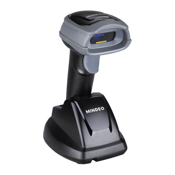
2-3 Parts of the scanner ④ ① ③ ② ⑤ Figure 2-2 Handheld unit ① Exit window ② Trigger (Press to triggr / Long press 2 seconds to turn on) ③ Beeper ④ Power indicator (Blue LED) ⑤ Successful decoding indicator (Green LED) / Communication fail indicator (Red LED) / Charging indicator (Red LED) ⑥... -
Page 17: Charge Battery
2-4 Charge battery Please charge the battery before the first time of use. The charge indicator (Red LED) on the handheld unit is turned on when the charging is in process. When the charging process completes, the red LED is turned off. Charging time: 4 hours for fully charged. -
Page 18: Installation Of Cable
2-5 Installation of cable Note: If any of the below operation is incorrect, turn off the power immediately and check the scanner for any improper connections. Go through all steps again. 2-5-1 PS/2 keyboard cable Plug one end of the PS/2 keyboard cable to the cradle, one end to PS/2 port on PC, and one end to the keyboard. -
Page 19: Cable
2-5-3 RS-232 cable Connect the DB9 serial communication cable with the cradle and the COM port of the computer. Plug the output of the AC/DC adaptor into the power terminal of on the cradle. Plug the AC/DC adaptor provided by the manufacturer into an electrical outlet. -
Page 20: Programming Menu
3 Programming menu When the scanner is scanning, ensure the scan line crosses every bar and space of the symbol. RIGHT WRONG 3-1 Example: Programming instruction Note: Only one parameter can be setup at each time. During the process of programming, LED is lighting to indicate the programming correctness. LED will go off if any incorrect programming operation performed. -
Page 21: Wireless Communication Setting
3-2 Wireless communication setting 3-2-1 Wireless communication setting for handheld unit Handheld unit RF channel No.: The scanner offers 16 different radio frequency channels for the data transmission between handheld unit and cradle. The number of channel can be increased. Handheld unit address: The scanner offers 2000 different four-digit radio addresses for handheld unit. - Page 22 not received data beyond the interval. If a RS232 is used, this value should be set not less than feedback delay of RS232 serial port transmission. Inform the result of wired transmission for handheld unit: If this option is enabled, the cradle will only inform the handheld unit the success of data transmission after the data has been successfully transmitted from cradle to host PC.
- Page 23 SETUP Option barcode Options Alpha. entry Single-scan setting 02-16 Handheld unit RF channel No. 02-16 0000-1999 Handheld unit address 0000-1999 0000* 10 dbm (maximum) 7 dbm 5 dbm Radio power level for handheld unit 0 dbm -5 dbm -10 dbm -15 dbm (minimum) Disable Frequency hopping...
- Page 24 Disable Save data at low-battery or power-off Enable Disable Low battery indicator Enable 00-FF Enter sleeping mode interval 00-FF (second) 00-FF Enter transmitting data mode interval 00-FF (minute) 02-20 Interval for radio communication 02-20 (second) Inform the result of wired transmission Disable for handheld unit Enable...
- Page 25 Join Show channel information of handheld unit...
-
Page 26: Wireless Communication Setting For Cradle
3-2-2 Wireless communication setting for cradle Radio power level for cradle: By selecting, you can change the radio frequency power level for cradle. SETUP Option barcode Options Alpha. entry Single-scan setting 10 dbm (maximum) 7 dbm 5 dbm Radio power level for cradle 0 dbm -5 dbm -10 dbm... -
Page 27: Example
3-2-3 Example Example 1: One handheld unit and one cradle The following takes channel No.5 for instance. Step 1): Set Handheld unit RF channel No. of the handheld unit to 5. Step 2): Set Handheld unit address of handheld unit to 0002. Step 3): Scan the following barcode to bind the handheld unit with the cradle. - Page 28 Example 2: Two handheld units and one cradle The following takes channel No.5 for instance. Step 1): Set Handheld unit RF channel No. of two handheld units to 5. Step 2): Set Handheld unit address of the first handheld unit to 0002. Step 3): Set Handheld unit address of the second handheld unit to 0003.
- Page 29 Step 4): Make the first handheld unit scan the following barcode to bind the handheld unit with the cradle. Firmly position the handheld unit onto the cradle. Within 10 seconds, two beeps will be emitted to signal that the cradle has been paired to the handheld unit, and the blue LED on the handheld unit will go off.
- Page 30 Example 3: Three handheld units and one cradle The following takes channel No.5 for instance. Step 1): Set Handheld unit RF channel No. of three handheld units to 5. Step 2): Set Handheld unit address of the first handheld unit to 0002. Step 3): Set Handheld unit address of the second handheld unit to 0003.
- Page 31 Step 4): Set Handheld unit address of the third handheld unit to 0004. Step 5): Make the first handheld unit scan the following barcode to bind the handheld unit with the cradle. Firmly position the handheld unit onto the cradle. Within 10 seconds, two beeps will be emitted to signal that the cradle has been paired to the handheld unit, and the blue LED on the handheld unit will go off.
-
Page 32: Keyboard Wedge Interface For Cradle
3-3 Keyboard wedge interface for Cradle Keyboard type: As a keyboard interface, the scanner supports most of the popular PCs and IBM terminals. Keyboard layout: The scanner supports different national keyboard layouts. Clock period: According to the PS/2 protocol, the clock is provided by the device, e.g. keyboard or scanner, with the period between 60 us to 100 us. - Page 33 SETUP Option bar code Option Alpha. entry Single-scan setting IBM AT, PS/2 Keyboard type Apple Mac compatibles Turkish F Turkish Q French Italian Keyboard layout Spanish Slovak Denmark Japanese German 60 us 70 us 80 us Clock period 90 us 100 us 200 us Delay-after-compound-key...
- Page 34 SETUP Option bar code Option Alpha. entry Single-scan setting 10 ms 20 ms 40 ms 80 ms Alphabetic key Numeric key Numeric keypad Alt+ keypad Disable Power-on simulation Enable 0 ms 5 ms 10 ms Inter-character delay 20 ms 40 ms 80 ms 1 ms 2 ms...
- Page 35 SETUP Option bar code Option Alpha. entry Single-scan setting Enable Disable Caps Lock override Enable...
-
Page 36: Interface For Cradle
3-4 RS-232 interface for Cradle Flow control: None-The communication only uses TxD and RxD signals without any hardware or software handshaking protocol. RTS/CTS-If the scanner wants to send the barcode data to host computer, it will issue the RTS signal first, wait for the CTS signal from the host computer, and then perform the normal data communication. - Page 37 SETUP Option bar code Option Alpha. entry Single-scan setting None RTS/CTS (Host idle: Low RTS) Flow control RTS/CTS (Host idle: High RTS) XON/XOFF ACK/NAK 0 ms 5 ms 10 ms Inter-character delay 20 ms 40 ms 80 ms Reserved 01-99 Response delay 01-99 (100 ms) Baud rate...
- Page 38 SETUP Option bar code Option Alpha. entry Single-scan setting 9600 19200 38400 57600 115200 None Parity Even 8 bits Data bit 7 bits One bit Stop bit Two bits...
-
Page 39: Usb Interface For Cradle
3-5 USB interface for Cradle USB device type: When the cradle is connected to a PC with a USB cable, it will be identified as a HID keyboard. HID keyboard– By setting, the scanner is used as a USB HID keyboard emulation device. The keyboard layout setting follows the setting of keyboard layout in the chapter of Keyboard wedge. - Page 40 SETUP Option bar code Option Alpha. entry Single-scan setting HID keyboard USB device type HID keyboard for Apple Mac USB virtual COM Turkish F Turkish Q French Italian Keyboard layout Spanish Slovak Denmark Japanese German 0 ms 5 ms 10 ms Inter-character delay 20 ms 40 ms...
- Page 41 SETUP Option bar code Option Alpha. entry Single-scan setting Alphabetic key Numeric key Numeric keypad Alt+ keypad...
-
Page 42: Handheld Scan & Some Global Settings
3-6 Handheld scan & some global settings Scanning mode: Good-read off-The trigger button must be pressed once to activate scanning. The light source of scanner stops scanning when there is a successful reading or no code is decoded after the Stand-by duration elapsed. - Page 43 function is not effective for all types of barcodes. SETUP Option bar code Option Alpha. entry Single-scan setting Good-read off Momentary Alternate Scan mode continue Continue Timeout off 01-99 Standby duration 01-99 (second) 00-FF Same barcode delay time 00-FF (50 ms) 00-09 Double confirm 00-09...
- Page 44 SETUP Option bar code Option Alpha. entry Single-scan setting 00-44 Global G1-G4 string selection 00-44 Disable Element amendment Enable Disable Character output restraint Enable Disable Decoder optimization Enable...
-
Page 45: Indication For Handheld Unit
3-7 Indication for handheld unit Power on alert: After power-on the scanner will generate an alert signal to indicate a successful self-test. LED indication: After each successful reading, the LED above the scanner will light up to indicate a good barcode reading. -
Page 46: Upc-A
3-8 UPC-A Read: Format System character Data digits (10 digits) Check digit Check digit verification: The check digit verification is optional. Check digit trans.: By setting Enable, check digit will be transmitted. Code ID setting: Code ID is a one-or-two-character string used to represent the symbol upon a succeeding reading. - Page 47 SETUP Option bar code Option Alpha. entry Single-scan setting 00-FF Code ID setting 00-FF (ASCII) <A>* 00-44 Insert group selection 00-44 None 2 digits Supplement digits 5 digits 2 or 5 digits None Truncate leading zeros Truncation/Expansion Expand to EAN-13 Truncate system character Add country code...
-
Page 48: Upc-E
3-9 UPC-E Read: Format System character “0” Data digits (6 digits) Check digits Check digit verification: The check digit verification is optional and made as the sum of the numerical value of the data digits. Check digit trans.: By setting Enable, check digit will be transmitted. 3-11 UPC-A Code ID setting: Refer to Code ID setting of 3-11 UPC-A... - Page 49 SETUP Option bar code Option Alpha. entry Single-scan setting Disable Check digit trans. Enable 00-FF Code ID setting 00-FF (ASCII) <D>* 00-44 Insert group selection 00-44 None 2 digits Supplement digits 5 digits 2 or 5 digits None Truncate leading zeros Expand to EAN-13 Truncation/Expansion Expand to UPC-A...
-
Page 50: Upc-E1
3-10 UPC-E1 Read: Format System character “1” Data digits (6 digits) Check digits Check digit verification: The check digit is optional and made as the sum of the numerical value of the data digits. Check digit trans.: By setting Enable, check digit will be transmitted. 3-11 UPC-A Code ID setting: Refer to Code ID setting of 3-11 UPC-A... - Page 51 SETUP Option bar code Option Alpha. entry Single-scan setting 00-FF Code ID setting 00-FF (ASCII) <D>* 00-44 Insert group selection 00-44 None 2 digits Supplement digits 5 digits 2 or 5 digits None Expand to EAN-13 Truncation/Expansion Expand to UPC-A Truncate system character Add country code...
-
Page 52: Isbn/Issn)
3-11 EAN-13 (ISBN/ISSN) Read: Format Data digits (12 digits) Check digit Check digit verification: The check digit is optional and made as the sum of the numerical value of the data digits. Check digit transmission: By setting Enable, check digit will be transmitted. 3-11 UPC-A EAN-13 code ID setting: Refer to Code ID setting of 3-11 UPC-A... - Page 53 SETUP Option bar code Option Alpha. entry Single-scan setting 00-FF EAN-13 code ID setting 00-FF (ASCII) <A>* 00-44 Insert group selection 00-44 None 2 digits Supplement digits 5 digits 2 or 5 digits Disable ISBN/ISSN conversion Enable 00-FF ISBN/ISSN code ID setting 00-FF (ASCII) <B>*...
-
Page 54: Ean-8
3-12 EAN-8 Read: Format Data digits (7 digits) Check digit Check digit verification: The check digit is optional and made as the sum of the numerical value of the data digits. Check digit trans.: By setting Enable, check digit will be transmitted. 3-11 UPC-A Code ID setting: Refer to Code ID setting of 3-11 UPC-A... - Page 55 SETUP Option bar code Option Alpha. entry Single-scan setting 00-44 Insert group selection 00-44 None 2 digits Supplement digits 5 digits 2 or 5 digits None Truncation/Expansion Truncate leading zero Expand to EAN-13...
-
Page 56: Code 39 (Code 32, Trioptic Code 39)
3-13 Code 39 (Code 32, Trioptic Code 39) Read: Format Start character (*) Data digits (variable) Check digit (optional) End character (*) Check digit verification: The check digit is optional and made as the sum module 43 of the numerical value of the data digits. - Page 57 SETUP Option bar code Option Alpha. entry Single-scan setting Disable Read Enable Disable Check digit verification Enable Disable Check digit transmission Enable 00-99 Max. code length 00-99 00-99 Min. code length 00-99 00-FF Code ID setting 00-FF (ASCII) <M>* 00-44 Insert group selection 00-44 Standard...
- Page 58 SETUP Option bar code Option Alpha. entry Single-scan setting Enable Disable Convert Code 39 to Code 32 Enable Disable Code 32 Prefix “A” transmission Enable Disable Trioptic Code 39 read Enable Disable Trioptic Code 39 Start/End transmission Enable Note 1: If Trioptic Code 39 is set Enable, Code 39 is forced Enable. Note 2: If Code 39 is set Disable, Trioptic Code 39 is forced Disable.
-
Page 59: Interleaved 2 Of 5
3-14 Interleaved 2 of 5 Read: Format Data digits (Variable) Check digit (optional) Check digit verification: The check digit is made as the sum module 10 of the numerical values of all data digits. There are two optional check digit algorithms: the specified Uniform Symbol Specification (USS) and the Optical Product Code Council (OPCC). - Page 60 SETUP Option bar code Option Alpha. entry Single-scan setting Disable Read Enable Disable Check digit verification OPCC Disable Check digit transmission Enable 00-99 Max. code length 00-99 00-99 Min. code length 00-99 00-FF Code ID setting 00-FF (ASCII) <I>* 00-44 Insert group selection 00-44...
-
Page 61: Industrial 2 Of 5
3-15 Industrial 2 of 5 Read: Format Data digits (variable) 3-13 Code 39 Max./Min. code length: Refer to Max./Min. code length of 3-11 UPC-A Code ID setting: Refer to Code ID setting of 3-11 UPC-A Insertion group selection: Refer to Insertion group selection of SETUP Option bar code Option... -
Page 62: Matrix 2 Of 5
3-16 Matrix 2 of 5 Read: Format Data digits (variable) Check digit (optional) Check digit verification: The check digit is made as the sum module 10 of the numerical values of all data digits. Check digit transmission: By setting Enable, check digit will be transmitted. 3-13 Code 39 Max./Min. - Page 63 SETUP Option bar code Option Alpha. entry Single-scan setting Disable Read Enable Disable Check digit verification Enable Disable Check digit transmission Enable 00-99 Max. code length 00-99 00-99 Min. code length 00-99 00-FF Code ID setting 00-FF (ASCII) <X>* 00-44 Insert group selection 00-44...
-
Page 64: Codabar
3-17 Codabar Read: Format Start character Data digits (variable) Check digit (optional) End character Check digit verification: The check digit is made as the sum module 16 of the numerical values of all data digits. Check digit transmission: By setting Enable, check digit will be transmitted. 3-13 Code 39 Max./Min. - Page 65 SETUP Option bar code Option Alpha. entry Single-scan setting 00-FF Code ID setting 00-FF (ASCII) <N>* 00-44 Insert group selection 00-44 ABCD/ABCD abcd/abcd Start/End type ABCD/TN*E abcd/tn*e Disable Start/End transmission Enable...
-
Page 66: Code 128
3-18 Code 128 Read: Format Data digits (variable) Check digit (optional) Check digit verification: The check digit is made as the sum module 103 of all data digits. Check digit transmission: By setting Enable, check digit will be transmitted. 3-13 Code 39 Max./Min. - Page 67 SETUP Option bar code Option Alpha. entry Single-scan setting 00-FF Code ID setting 00-FF (ASCII) <K>* 00-44 Insert group selection 00-44 Disable Truncate leading zeros All leading “0”s Only the first “0”...
-
Page 68: Ucc/Ean 128
3-19 UCC/EAN 128 Read: Format Data digits (variable) Check digit (optional) Check digit verification: The check digit is made as the sum module 103 of all data digits. Check digit transmission: By setting Enable, check digit will be transmitted. 3-13 Code 39 Max. - Page 69 SETUP Option bar code Option Alpha. entry Single-scan setting Disable Read Enable Disable Check digit verification Enable Disable Check digit transmission Reserved 00-99 Max. code length 00-99 00-99 Min. code length 00-99 00-FF Code ID setting 00-FF (ASCII) <K>* 00-44 Insert group selection 00-44 Disable...
-
Page 70: Isbt 128
3-20 ISBT 128 Read: Format “=” or “&” Data digits (variable) Check digit (optional) Check digit verification: The check digit is made as the sum module 103 of all data digits. Check digit transmission: By setting Enable, check digit will be transmitted. 3-13 Code 39 Max./Min. - Page 71 SETUP Option bar code Option Alpha. entry Single-scan setting Disable Read Enable Disable Check digit verification Enable Disable Check digit transmission Reserved 00-99 Max. code length 00-99 00-99 Min. code length 00-99 00-FF Code ID setting 00-FF (ASCII) <K>* 00-44 Insert group selection 00-44...
-
Page 72: Code 93
3-21 Code 93 Read: Format Data digits (variable) 2 check digits (optional) Check digit verification: The check digit is made as the sum module 47 of the numerical values of all data digits. Check digit transmission: By setting Enable, check digit will be transmitted. 3-13 Code 39 Max./Min. - Page 73 SETUP Option bar code Option Alpha. entry Single-scan setting Disable Read Enable Disable Check digit verification Enable Disable Check digit transmission Enable 00-99 Max. code length 00-99 00-99 Min. code length 00-99 00-FF Code ID setting 00-FF (ASCII) <L>* 00-44 Insert group selection 00-44...
- Page 74 3-22 Code 11 Read: Format Data digits (variable) Check digit 1 (optional ) Check digit 2 (optional) Check digit verification: The check digit is presented as the sum module 11 of all data digits. Check digit transmission: By setting Enable, check digit 1 and check digit 2 will be transmitted upon your selected check digit verification method.
- Page 75 SETUP Option bar code Option Alpha. entry Single-scan setting Disable Read Enable Disable One digit Check digit verification Reserved Reserved Disable Check digit transmission Enable 00-99 Max. code length 00-99 00-99 Min. code length 00-99 00-FF Code ID setting 00-FF (ASCII) <V>* 00-44...
-
Page 76: Code 11
3-23 MSI/Plessey Read: Format Data digits (variable) Check digit 1 (optional) Check digit 2 (optional) Check digit verification: The MSI/Plessey has one or two optional check digits. There are three methods of verifying check digits, i.e. Mod 10, Mod 10/10 and Mod 10/11. The check digit 1 and check digit 2 will be calculated as the sum module 10 or 11 of the data digits. - Page 77 SETUP Option bar code Option Alpha. entry Single-scan setting Disable Read Enable Disable 1 digit (Mod 10) Check digit verification 2 digits (Mod 10/10) 2 digits (Mod 10/11) Disable Check digit transmission Enable 00-99 Max. code length 00-99 00-99 Min. code length 00-99 00-FF Code ID setting...
-
Page 78: Uk/Plessey
3-24 UK/Plessey Read: Format Data digits (variable) 2 check digits (optional) Check digit verification: The UK/Plessey has one or two optional check digits. The check digit 1 and check digit 2 will be calculated as the sum module 10 or 11 of the data digits. Check digit transmission: By setting Enable, check digit will be transmitted. - Page 79 SETUP Option bar code Option Alpha. entry Single-scan setting Disable Read Enable Disable Check digit verification Enable Disable Check digit transmission Enable 00-99 Max. code length 00-99 00-99 Min. code length 00-99 00-FF Code ID setting 00-FF (ASCII) <U>* 00-44 Insert group selection 00-44...
-
Page 80: China Post
3-25 China Post Read: Format 11 Data digits 3-13 Code 39 Max. /Min. code length: Refer to Max./Min. code length of . The code length of China Post is 11. 3-11 UPC-A Code ID setting: Refer to Code ID setting of 3-11 UPC-A Insertion group selection: Refer to Insertion group selection of SETUP... -
Page 81: China Finance
3-26 China Finance Note: This type of barcode is not Omni-directionally decodable. The encodable character set includes numeric 0 to 9. Among the symbol of 0 to 9, 0 and 2, 4 and 9, 5 and 8, 6 and 7, have the symmetrical pattern;... - Page 82 SETUP Option bar code Option Alpha. entry Single-scan setting Disable Read Enable 00-99 Max. code length 00-99 00-99 Min. code length 00-99 Disable Check digit verification Reserved Disable Enable Only 5 converted to A Leading character 5/6/7/8/9 converted to A/B/C/D/E Only 6 converted to B Only 7 converted to C Only 8 converted to D...
- Page 83 SETUP Option bar code Option Alpha. entry Single-scan setting Assigned to 7(C) Assigned to 8(D) Assigned to 9(E) Assigned to 1 Assigned to 2 Assigned to 3 Assigned to 4 00-FF Code ID setting 00-FF (ASCII) <Y>* 00-44 Insert group selection 00-44 Laser Light Direction Setting: By scanning the barcode above, the decoding direction of the scanner’s laser light is from left to right.
-
Page 84: Gs1 Databar (Gs1 Databar Truncated)
3-27 GS1 DataBar (GS1 DataBar Truncated) GS1 DataBar Truncated is structured and encoded the same as the standard GS1 DataBar format, except its height is reduced to a 13 modules minimum; while GS1 DataBar should have a height greater than or equal to 33 modules. Read: Format 16 Data digits... -
Page 85: Gs1 Databar Limited
3-28 GS1 DataBar Limited Read: Format 16 Data digits 3-11 UPC-A Code ID setting: Refer to Code ID setting of 3-11 UPC-A Insertion group selection: Refer to Insertion group selection of 3-27 GS1 DataBar (GS1 DataBar Truncated) Conversion: Refer to Conversion of SETUP Option bar code Option... -
Page 86: Gs1 Databar Expanded
3-29 GS1 DataBar Expanded Read: Format Data characters (variable) 3-11 UPC-A Code ID setting: Refer to Code ID setting of 3-11 UPC-A Insertion group selection: Refer to Insertion group selection of Conversion: 3-32 String transmission UCC/EAN 128- Refer to Code ID transmission of , ]Cm will be identified as AIM ID. -
Page 87: G1-G4 & Fn1 Substitution String Setting
3-30 G1-G4 & FN1 substitution string setting Format of barcode data transmission: Prefix Code name Preamble Code ID Code length Code data Code ID Postamble Suffix Suffix string setting: The <enter > key is represented in different ASCII when it is applied by different OS. For a Windows/DOS OS, <enter>... - Page 88 Testing barcode: FN1 substitution string setting: The FN1 character (0x1D) in an UCC/EAN128 barcode, or a Code 128 barcode, or a GS1 DataBar barcode can be substituted with a defined string. Single character C1/C2 replacement: By setting, a defined character in the data string can be replaced by another defined character.
- Page 89 SETUP Option bar code Option Alpha. entry Single-scan setting 0-22 characters 00-FF Prefix string setting None 0-22 characters 00-FF Suffix string setting <ENTER> 0D0A* 0-22 characters 00-FF Preamble string setting None 0-22 characters 00-FF Postamble string setting None 0-22 characters 00-FF Insert G1 string setting None...
- Page 90 SETUP Option bar code Option Alpha. entry Single-scan setting 0000-FFFF 0000* Single character C2 replacement 0000-FFFF 0000-FFFF...
-
Page 91: G1-G4 String Position & Code Id Position
3-31 G1-G4 string position & Code ID position Format of barcode data transmission: Prefix Code name Preamble Code ID Code length Code data Code ID Postamble Suffix Insert G1/G2/G3/G4 string position: The scanner offers 4 positions to insert strings among the symbol. In case of the insertion position is greater than the length of the symbol, the insertion of string is not effective. -
Page 92: String Transmission
3-32 String transmission Note: The information in this chapter is closely related to the chapter of String setting. Format of barcode data transmission: Prefix Code name Preamble Code ID Code length Code data Code ID Postamble Suffix Prefix transmission: By setting Enable, prefix will be appended before the data transmitted. Suffix transmission: By setting Enable, suffix will be appended after the data is transmitted. - Page 93 SETUP Option bar code Option Alpha. entry Single-scan setting Disable Prefix transmission Enable Disable Suffix transmission Enable Disable Code name transmission Enable Disable Preamble transmission Enable Disable Postamble transmission Enable Disable Code ID transmission Proprietary ID AIM ID Disable Code length transmission Enable Disable Upper (data only)
- Page 94 SETUP Option bar code Option Alpha. entry Single-scan setting Lower (whole string) Disable FN1 substitution transmission Enable All-non-printable-character string Disable transmission with string setting Enable 01-99 01-99 Transmit the first N data characters only 01-99 01-99 Transmit the last N data characters only...
-
Page 95: Troubleshooting
4 Troubleshooting Problem: Nothing happens when you follow the operating instructions, or the scanner displays erratic behavior. Possible causes: No power to the scanner. Incorrect cables. Connections are loose. Possible solutions: Check the system power. Ensure the power supply is connected. Use the original cables. -
Page 96: Maintenance
5 Maintenance Cleaning the exit window is the only maintenance required. A dirty window may affect scanning accuracy. Do not allow any abrasive material to touch the window. Remove any dirt particles with a damp cloth. Wipe the window using a tissue moistened with water. Do not spray water or other cleaning liquids directly into the window. -
Page 97: Ascii Table
6 ASCII table for keyboard wedge for RS-232 Null Down Left Right PgUp PgDn Home Enter Insert Ctrl+ Delete Alt+ Notes: The 2nd and the 3rd columns above are used for keyboard wedge only. “ & ‘ < > Example: ASCII “A” = “41”. -
Page 98: Barcode Representing Non-Printable Character
7 Barcode representing non-printable character Notes to make the following barcode: 1. According to different barcode printing software, the method of printing following barcode is different. 2. If using CODESOFT software, firstly read the information through “Help→Index→Code128→Special input syntax”. Also refer to ASCII table. For example, if we wish to make “F1” barcode, select “Code128”, then select “CODE A”... -
Page 99: Quick Setting To Wireless Network
8 Quick setting to wireless network The steps of setting are: 1. Both the handheld unit and the cradle are in normal working mode. Normally it means that only the blue LED on the handheld unit and only the blue LED on the cradle are ON as shown below. 2. -
Page 100: Test Chart
9 Test Chart UPC-A UPC-E UPC-E1 (Default setting: Disable) EAN-13 ISBN/ISSN EAN-8 Code 39 Code 32 A908765439 Trioptic Code 39 Interleaved 2 of 5 Industrial 2 of 5 (Default setting: Disable) Matrix 2 of 5 Codabar... - Page 101 Test chart (continue) Code 128 UCC/EAN 128 ISBT 128 Code 93 Code 11 (Default setting: Disable) MSI/Plessey (Default setting: Disable) UK/Plessey China Post GS1 DataBar (GS1 DataBar Truncated) GS1 DataBar Limited GS1 DataBar Expanded...
-
Page 102: Return Default Parameters
10 Return default parameters All parameters of handheld unit return to default setting WARNING: If you wish to return all parameters of the handheld unit, including radio communication setting, to default setting, please scan the barcode above. All parameters of cradle return to default setting WARNING: If you wish to return all parameters of the cradle, including radio communication setting, to default setting, please scan the barcode above. -
Page 103: Display Firmware Version & Radio Communication Setting
11 Display firmware version & radio communication setting Cradle firmware version display If you wish to display the firmware version of the cradle, please scan the barcode above. Handheld unit firmware version display If you wish to display the firmware version of the handheld unit, please scan the barcode above. Cradle radio communication setting display If you wish to display the radio communication setting of the cradle, please scan the barcode above. -
Page 104: Configuration Alphanumeric Entry Barcode
12 Configuration alphanumeric entry barcode To finish parameter setting, please scan the barcode below.
Need help?
Do you have a question about the CS2190 and is the answer not in the manual?
Questions and answers