Table of Contents
Advertisement
Quick Links
Advertisement
Table of Contents

Subscribe to Our Youtube Channel
Summary of Contents for Supermicro 6048R-DE2CR24L
- Page 1 SuperStoreSystem 6048R-DE2CR24L User's Manual Revision 1.0...
- Page 2 This product, including software and documentation, is the property of Supermicro and/or its licensors, and is supplied only under a license. Any use or reproduction of this product is not allowed, except as expressly permitted by the terms of said license.
- Page 3 Preface About This Manual This manual is written for professional system integrators and PC technicians. It provides information for the installation and use of the 6048R-DE2CR24L SuperStoreSystem. Installation and maintenance for this system should be performed by experienced technicians only.
- Page 4 SUPERSTORESYSTEM 6048R-DE2CR24L User's Manual Chapter 5: Advanced Serverboard Setup Chapter 5 provides detailed information on the X10DRS serverboard, including the locations and functions of connections, headers and jumpers. Refer to this chapter when adding or removing processors or main memory and when reconfi guring the serverboard.
- Page 5 Preface Notes...
-
Page 6: Table Of Contents
SUPERSTORESYSTEM 6048R-DE2CR24L User's Manual Table of Contents Chapter 1 Introduction Overview ......................1-1 Serverboard Features ..................1-2 Processors ...................... 1-2 Memory ......................1-2 SAS Disk Controller ..................1-2 SAS Expander ....................1-2 SATA ......................1-2 NTB Connectivity .................... 1-2 PCI Expansion Slots ..................1-3 Rear Chassis Ports .................. - Page 7 Table of Contents Installing the System into a Rack ..............2-4 Installing the Inner Rack Rails ................ 2-4 Installing the Outer Rack Rails ............... 2-5 Installing the Chassis into a Rack..............2-6 Chapter 3 System Interface Overview ......................3-1 Control Panel Button ..................3-1 Power ......................
- Page 8 SUPERSTORESYSTEM 6048R-DE2CR24L User's Manual Installing the Processor and Heatsink ............5-3 Installing an LGA2011 Processor ..............5-3 Installing a CPU Heatsink ................5-6 Removing the Heatsink ................... 5-6 Installing Memory .................... 5-7 Memory Support ....................5-7 DIMM Installation .................... 5-7 Installing PCI Add-On Cards ................
- Page 9 Table of Contents Main Setup ...................... 7-2 Advanced Setup Confi gurations..............7-4 Event Logs ....................7-32 IPMI ....................... 7-34 Security Settings ................... 7-36 Boot Settings ....................7-39 This submenu allows the user to confi gure Boot settings for this system: ..... 7-39 Save &...
- Page 10 SUPERSTORESYSTEM 6048R-DE2CR24L User's Manual Notes...
-
Page 11: Chapter 1 Introduction
Chapter 1 Introduction Overview The 6048R-DE2CR24L is a high-end Super Storage Bridge Bay (SBB) system comprised of two main subsystems: the SC947ETS-R0NDBP chassis and two X10DRS dual processor serverboards. Please refer to our web site for information on operating systems that have been certifi ed for use with the system (www. -
Page 12: Serverboard Features
SUPERSTORESYSTEM 6048R-DE2CR24L User's Manual Serverboard Features The 6048R-DE2CR24L SuperStoreSystem is built around two X10DRS serverboards for a dual-node system that shares storage resources as well as features a dedicated PCI-E bus between server nodes for High Availability (HA), Cluster in a Box (CiB) applications The X10DRS is a dual processor serverboard based on the Intel®... -
Page 13: Pci Expansion Slots
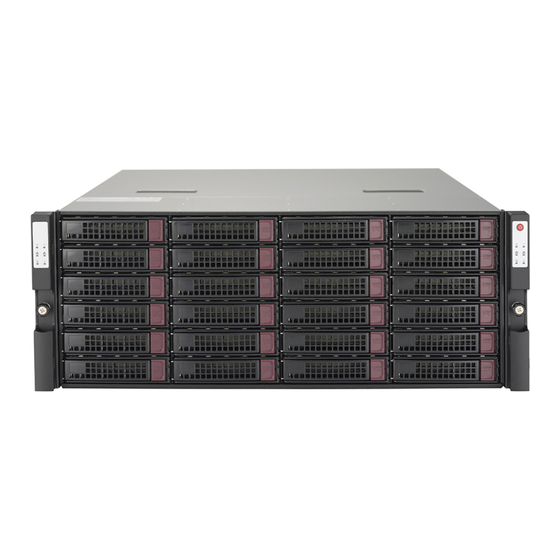
These drives are hot-swappable units and are connected to a midplane that provides power and control. Front Control Panel Two control panels are included on each end of the 6048R-DE2CR24L SuperStoreSystem to provide you with system monitoring and control. LEDs indicate system power, network (NIC) activity, system overheat and power supply failure. -
Page 14: Cooling System
SUPERSTORESYSTEM 6048R-DE2CR24L User's Manual Cooling System The SC947ETS-R0NDBP chassis has four (4) 8-cm fans behind HDD backplane and two (2) back-to-back, 4-cm counter-rotating fans at the rear of each node. This counter-rotating action works to dampen vibration levels while generating exceptional airfl... -
Page 15: Contacting Supermicro
Super Micro Computer, Inc. 980 Rock Ave. San Jose, CA 95131 U.S.A. Tel: +1 (408) 503-8000 Fax: +1 (408) 503-8008 Email: marketing@supermicro.com (General Information) support@supermicro.com (Technical Support) Web Site: www.supermicro.com Europe Address: Super Micro Computer B.V. Het Sterrenbeeld 28, 5215 ML... -
Page 16: Sbb: Storage Bridge Bay
SUPERSTORESYSTEM 6048R-DE2CR24L User's Manual SBB: Storage Bridge Bay The 6048R-DE2CR24L Super SBB was designed to function as a fully redundant, fault-tolerant "cluster-in-a-box" system. The standard support for twenty-four (24) 3.5" hot-swap HDDs (SAS2 or SAS3) may be expanded to support additional storage with the optional SBB JBOD SSG-947R-E2CJB confi... -
Page 17: Chapter 2 Server Installation
Unpacking the System You should inspect the box the 6048R-DE2CR24L was shipped in and note if it was damaged in any way. If the server itself shows damage you should fi le a damage claim with the carrier who delivered it. -
Page 18: Choosing A Setup Location
SUPERSTORESYSTEM 6048R-DE2CR24L User's Manual Choosing a Setup Location • Leave enough clearance in front of the rack to enable you to open the front door completely (~25 inches) and approximately 30 inches of clearance in the back of the rack to allow for suffi cient airfl ow and ease in servicing. -
Page 19: Rack Mounting Considerations
Chapter 2: Server Installation Rack Mounting Considerations Ambient Operating Temperature If installed in a closed or multi-unit rack assembly, the ambient operating temperature of the rack environment may be greater than the ambient temperature of the room. Therefore, consideration should be given to installing the equipment in an environment compatible with the manufacturer’s maximum rated ambient temperature (Tmra). -
Page 20: Installing The System Into A Rack
SUPERSTORESYSTEM 6048R-DE2CR24L User's Manual • If the rack is provided with stabilizing devices, install the stabilizers before mounting or servicing the unit in the rack. Installing the System into a Rack This section provides information on installing the SC947 chassis into a rack unit with the quick-release rails provided. -
Page 21: Installing The Outer Rack Rails
Chapter 2: Server Installation Installing the Outer Rack Rails Outer rails attach to the server rack and hold the server in place. The outer rails for the SC947 chassis extend between 30 inches and 33 inches. Installing the Outer Rails 1. -
Page 22: Installing The Chassis Into A Rack
SUPERSTORESYSTEM 6048R-DE2CR24L User's Manual Installing the Chassis into a Rack Installing into a Rack 1. Confi rm that the inner and outer rails are properly installed. 2. Line up the inner (chassis) rails with the front of the outer (rack) rails. -
Page 23: Chapter 3 System Interface
Chapter 3: System Interface Chapter 3 System Interface Overview There are several LEDs on two control panels as well as others on the drive carriers to keep you constantly informed of the overall status of the system as well as the activity and health of specifi... -
Page 24: Heartbeat
SUPERSTORESYSTEM 6048R-DE2CR24L User's Manual Heartbeat On the 6048R-DE2CR24L, this is a serverboard heartbeat LED and indicates that power is being supplied to the serverboard. NIC1 Indicates network activity on the LAN1 port when fl ashing. NIC2 Indicates network activity on the LAN2 port when fl ashing. -
Page 25: Drive Carrier Leds
Chapter 3: System Interface Drive Carrier LEDs Each drive carrier has two LEDs: • Green: When illuminated, the green LED on the drive carrier indicates the drive is powered on. If this LED is not lit, it means no power is being provided for the drive. - Page 26 SUPERSTORESYSTEM 6048R-DE2CR24L User's Manual Notes...
-
Page 27: Chapter 4 Standardized Warning Statements For Ac Systems
Only certifi ed technicians should attempt to install or confi gure components. Read this chapter in its entirety before installing or confi guring components in the Supermicro chassis. Some warnings may not apply for your system. These warnings may also be found on our web site at www.supermicro.com/about/ policies/safety_information.cfm. - Page 28 SUPERSTORESYSTEM 6048R-DE2CR24L User's Manual Warnung WICHTIGE SICHERHEITSHINWEISE Dieses Warnsymbol bedeutet Gefahr. Sie befi nden sich in einer Situation, die zu Verletzungen führen kann. Machen Sie sich vor der Arbeit mit Geräten mit den Gefahren elektrischer Schaltungen und den üblichen Verfahren zur Vorbeugung vor Unfällen vertraut.
- Page 29 Chapter 4: Warning Statements for AC Systems ﺟﺴﺪﯾﺔ اﺻﺎﺑﺔ ﺗﺘﺴﺒﺐ ﻓﻲ ﺣﺎﻟﺔ ﯾﻤﻜﻦ أن اﻧﻚ ﻓﻲ ﺧﻄﺮ ﯾﻌﻨﻲ ھﺬا اﻟﺮﻣﺰ !ﺗﺤﺬﯾﺮ اﻟﺪواﺋﺮ ﺑﺎﻟﻤﺨﺎطﺮ اﻟﻨﺎﺟﻤﺔ ﻋﻦ ﻦ ﻋﻠﻰ ﻋﻠﻢ ، ﻛ ﻣﻌﺪات ﺗﻌﻤﻞ ﻋﻠﻰ أي ﻗﺒﻞ أن اﻟﻜﮭﺮﺑﺎﺋﯿﺔ ﺣﻮادث أي وﻗﻮع ﻤﻨﻊ...
-
Page 30: Installation Instructions
SUPERSTORESYSTEM 6048R-DE2CR24L User's Manual Installation Instructions Warning! Read the installation instructions before connecting the system to the power source. 設置手順書 システムを電源に接続する前に、 設置手順書をお読み下さい。 警告 将此系统连接电源前,请先阅读安装说明。 警告 將系統與電源連接前,請先閱讀安裝說明。 Warnung Vor dem Anschließen des Systems an die Stromquelle die Installationsanweisungen lesen. ¡Advertencia! Lea las instrucciones de instalación antes de conectar el sistema a la red de alimentación. -
Page 31: Circuit Breaker
Chapter 4: Warning Statements for AC Systems Circuit Breaker Warning! This product relies on the building's installation for short-circuit (overcurrent) protection. Ensure that the protective device is rated not greater than: 250 V, 20 A. サーキッ ト ・ ブレーカー この製品は、 短絡 (過電流) 保護装置がある建物での設置を前提としています。 保護装置の定格が250 V、... -
Page 32: Power Disconnection Warning
SUPERSTORESYSTEM 6048R-DE2CR24L User's Manual 경고! 이 제품은 전원의 단락(과전류)방지에 대해서 전적으로 건물의 관련 설비에 의존합니다. 보호장치의 정격이 반드시 250V(볼트), 20A(암페어)를 초과하지 않도록 해야 합니다. Waarschuwing Dit product is afhankelijk van de kortsluitbeveiliging (overspanning) van uw electrische installatie. Controleer of het beveiligde aparaat niet groter gedimensioneerd is dan 220V, 20A. - Page 33 Chapter 4: Warning Statements for AC Systems ¡Advertencia! El sistema debe ser disconnected de todas las fuentes de energía y del cable eléctrico quitado de los módulos de fuente de alimentación antes de tener acceso el interior del chasis para instalar o para quitar componentes de sistema. Attention Le système doit être débranché...
-
Page 34: Equipment Installation
SUPERSTORESYSTEM 6048R-DE2CR24L User's Manual Equipment Installation Warning! Only trained and qualifi ed personnel should be allowed to install, replace, or service this equipment. 機器の設置 トレーニングを受け認定された人だけがこの装置の設置、 交換、 またはサービスを許可 されています。 警告 只有经过培训且具有资格的人员才能进行此设备的安装、更换和维修。 警告 只有經過受訓且具資格人員才可安裝、更換與維修此設備。 Warnung Das Installieren, Ersetzen oder Bedienen dieser Ausrüstung sollte nur geschultem, qualifi... -
Page 35: Restricted Area
Chapter 4: Warning Statements for AC Systems Waarschuwing Deze apparatuur mag alleen worden geïnstalleerd, vervangen of hersteld door geschoold en gekwalifi ceerd personeel. Restricted Area Warning! This unit is intended for installation in restricted access areas. A restricted access area can be accessed only through the use of a special tool, lock and key, or other means of security. -
Page 36: Battery Handling
SUPERSTORESYSTEM 6048R-DE2CR24L User's Manual אזור עם גישה מוגבלת !אזהרה יש להתקין את היחידה באזורים שיש בהם הגבלת גישה. הגישה ניתנת בעזרת .('כלי אבטחה בלבד )מפתח, מנעול וכד ﻣﺤﻈﻮرة ﻣﻨﺎطﻖ ﻟﺘﺮﻛﯿﺒﮭﺎ ﻓﻲ ھﺬه اﻟﻮﺣﺪة ﺗﺨﺼﯿﺺ ﺗﻢ ،أداة ﺧﺎﺻﺔ ﻣﻦ ﺧﻼل اﺳﺘﺨﺪام... - Page 37 Chapter 4: Warning Statements for AC Systems Warnung Bei Einsetzen einer falschen Batterie besteht Explosionsgefahr. Ersetzen Sie die Batterie nur durch den gleichen oder vom Hersteller empfohlenen Batterietyp. Entsorgen Sie die benutzten Batterien nach den Anweisungen des Herstellers. Attention Danger d'explosion si la pile n'est pas remplacée correctement. Ne la remplacer que par une pile de type semblable ou équivalent, recommandée par le fabricant.
-
Page 38: Redundant Power Supplies (If Applicable To Your System)
SUPERSTORESYSTEM 6048R-DE2CR24L User's Manual Redundant Power Supplies (if applicable to your system) Warning! This unit might have more than one power supply connection. All connections must be removed to de-energize the unit. 冗長電源装置 このユニッ トは複数の電源装置が接続されている場合があります。 ユニッ トの電源を切るためには、 すべての接続を取り外さなければなりません。 警告 此部件连接的电源可能不止一个,必须将所有电源断开才能停止给该部件供电。... -
Page 39: Backplane Voltage (If Applicable To Your System)
Chapter 4: Warning Statements for AC Systems اﻣﺪاد اﻟﻄﺎﻗﺔ ﺑﻮﺣﺪات ﻋﺪة اﺗﺼﺎﻻت ﺠﮭﺎز اﻟ ﯾﻜﻮن ﻟﮭﺬا ﻗﺪ اﻟﻜﮭﺮﺑﺎء ﻋﻦ ﻮﺣﺪة اﻟ ﻟﻌﺰل ﻛﺎﻓﺔ اﻻﺗﺼﺎﻻت ﯾﺠﺐ إزاﻟﺔ 경고! 이 장치에는 한 개 이상의 전원 공급 단자가 연결되어 있을 수 있습니다. 이 장치에... -
Page 40: Comply With Local And National Electrical Codes
SUPERSTORESYSTEM 6048R-DE2CR24L User's Manual מתח בפנל האחורי !הרה אז קיימת סכנת מתח בפנל האחורי בזמן תפעול המערכת. יש להיזהר במהלך .העבודה اﻟﻠﻮﺣﺔ أواﻟﻄﺎﻗﺔ اﻟﻤﻮﺟﻮدة ﻋﻠﻰ اﻟﺘﯿﺎر اﻟﻜﮭﺮﺑﺎﺋﻲ ﻣﻦ ﺧﻄﺮ ھﻨﺎك ھﺬا اﻟﺠﮭﺎز ﺧﺪﻣﺔ ﻛﻦ ﺣﺬرا ﻋﻨﺪ ﯾﻌﻤﻞ اﻟﻨﻈﺎم ﻋﻨﺪﻣﺎ ﯾﻜﻮن... -
Page 41: Product Disposal
Chapter 4: Warning Statements for AC Systems Attention L'équipement doit être installé conformément aux normes électriques nationales et locales. תיאום חוקי החשמל הארצי !אזהרה הציוד חייבת להיות תואמת לחוקי החשמל המקומיים והארציים התקנת اﻟﻤﺘﻌﻠﻘﺔ اﻟﻤﺤﻠﯿﺔ واﻟﻮطﻨﯿﺔ ﻘﻮاﻧﯿﻦ ﯾﺠﺐ أن ﯾﻤﺘﺜﻞ ﻟﻠ اﻟﻜﮭﺮﺑﺎﺋﯿﺔ... -
Page 42: Hot Swap Fan Warning (If Applicable To Your System)
SUPERSTORESYSTEM 6048R-DE2CR24L User's Manual ¡Advertencia! Al deshacerse por completo de este producto debe seguir todas las leyes y reglamentos nacionales. Attention La mise au rebut ou le recyclage de ce produit sont généralement soumis à des lois et/ou directives de respect de l'environnement. Renseignez-vous auprès de l'organisme compétent. - Page 43 Chapter 4: Warning Statements for AC Systems 警告 當您從機架移除風扇裝置,風扇可能仍在轉動。小心不要將手指、螺絲起子和其他物品 太靠近風扇。 Warnung Die Lüfter drehen sich u. U. noch, wenn die Lüfterbaugruppe aus dem Chassis genommen wird. Halten Sie Finger, Schraubendreher und andere Gegenstände von den Öffnungen des Lüftergehäuses entfernt. ¡Advertencia! Los ventiladores podran dar vuelta cuando usted quite ell montaje del ventilador del chasis.
-
Page 44: Power Cable And Ac Adapter
fi re. Electrical Appliance and Material Safety Law prohibits the use of UL or CSA -certifi ed cables (that have UL/CSA shown on the code) for any other electrical devices than products designated by Supermicro only. 電源コードとACアダプター... - Page 45 Appareils électroménagers et de loi sur la sécurité Matériel interdit l'utilisation de UL ou CSA câbles certifi és qui ont UL ou CSA indiqué sur le code pour tous les autres appareils électriques que les produits désignés par Supermicro seulement.
- Page 46 SUPERSTORESYSTEM 6048R-DE2CR24L User's Manual Notes 4-20...
-
Page 47: Chapter 5 Advanced Serverboard Setup
Chapter 5: Advanced Serverboard Setup Chapter 5 Advanced Serverboard Setup This chapter provides detailed information on the X10DRS serverboard. All serverboard jumpers and connections are described. A layout and quick reference chart are also included in this chapter for your reference. Remember to completely close the chassis when you have fi... -
Page 48: Cable And Device Connectiions
SUPERSTORESYSTEM 6048R-DE2CR24L User's Manual Cable and Device Connections All data and power connections between the serverboard to the system (including the power supplies and the hard drives) are provided through the midplane. Most of these connections are made automatically when the system is assembled. "Right"... -
Page 49: Installing The Processor And Heatsink
CPU socket cap is in place and none of the socket pins are bent; otherwise, contact your retailer immediately. • Refer to the Supermicro web site for updates on CPU support. Installing an LGA2011 Processor 1. There are two levers on the... - Page 50 SUPERSTORESYSTEM 6048R-DE2CR24L User's Manual 3. With the lever labeled 'Close 1st' fully retracted, gently push down on the 'Open 1st' lever to open the load plate. Lift the load plate to open it completely. Gently push 4. Using your thumb and the index down to pop fi...
- Page 51 Chapter 5: Advanced Serverboard Setup • Warning: You can only install the CPU to the socket in one direction. Make sure that the CPU is properly inserted into the socket before closing the load plate. If it doesn't close properly, do not force it as it may damage your CPU. Instead, open the load plate again and double-check that the CPU is aligned properly.
-
Page 52: Installing A Cpu Heatsink
SUPERSTORESYSTEM 6048R-DE2CR24L User's Manual Installing a CPU Heatsink 1. Remove power from the system and unplug the AC power cord from the power supply. 2. Place the heatsink on top of the CPU so that the four mounting holes are aligned with those on the (preinstalled) heatsink retention mechanism. -
Page 53: Installing Memory
1 TB of LRDIMM (Load Reduced) or 512 GB of Registered (RDIMM) DDR4 (288-pin) ECC 2400/2133/1866/1600 MHz memory. See the following tables for memory installation. For the latest memory updates, please refer to the Supermicro website. DIMM Installation Installing Memory Modules 1. - Page 54 SUPERSTORESYSTEM 6048R-DE2CR24L User's Manual DIMM Module Population Confi guration Memory speed support depends on the CPUs installed in your system. For the latest memory updates, please refer to our website at http://www.supermicro.com/ products/motherboard. For memory to work properly, follow the tables below for memory installation.
-
Page 55: Installing Pci Add-On Cards
Chapter 5: Advanced Serverboard Setup Installing PCI Add-On Cards Each node in the 6048R-DE2CR24L can accommodate up to three PCI-E 3.0 x8 add-on cards. Installing an Add-on Card (Figure 5-4) 1. Begin by removing the node you wish to populate with add-on cards. -
Page 56: Serverboard Details
SUPERSTORESYSTEM 6048R-DE2CR24L User's Manual Serverboard Details Figure 5-5. X10DRS Layout (not drawn to scale) External VGA/USB1/2(2.0)COM1 JLAN2 JLAN1 JKVM1 CTRL X10DRS REV:1.03 BIOS FLASH CPU1 JBT1 BIOS LICENSE Battery HDD_LED2 LEDS_OV1 CPU2 Expander (Synch) BAR CODE MAC CODE (PCI-E Switch) - Page 57 Chapter 5: Advanced Serverboard Setup X10DRS Quick Reference Jumper Description Default Setting JBT1 Clear CMOS See Section 5-8 JPB1 BMC Enable/Disable Pins 1-2 (Enabled) JPG1 VGA Enable/Disable Pins 1-2 (Enabled) JPL1 10G(T) LAN1/2 Enable/Disable Pins 1-2 (Enabled) JPME2 Manufacture (ME) Mode Select Pins 1-2 (Normal) JWD1 Watch Dog Timer Enable/Disable...
-
Page 58: Connector And Port Defi Nitions
SUPERSTORESYSTEM 6048R-DE2CR24L User's Manual Connector and Port Defi nitions VGA/COM1/USB 2.0 Connector (JKVM1) A VGA/COM1/USB 2.0 connector is located next to LAN2 on the I/O back panel. JKVM1 provides a video port as well as serial and USB (2.0) connections with SMCI-proprietary cable (CBL-0218L) connected to JKVM1. - Page 59 Chapter 5: Advanced Serverboard Setup Fan Headers Fan Header Pin Defi nitions The X10DRS has eight fan headers Pin# Defi nition (Fan1 - Fan8). These 4-pin fans headers Ground are backward compatible with traditional +12V 3-pin fans (which do not support fan speed control).
-
Page 60: Jumper Settings
SUPERSTORESYSTEM 6048R-DE2CR24L User's Manual Jumper Settings Explanation of Jumpers Connector To modify the operation of the Pins serverboard, jumpers can be used to choose between optional settings. Jumpers create shorts between two Jumper pins to change the function of the connector. - Page 61 Chapter 5: Advanced Serverboard Setup Watch Dog Enable/Disable Watch Dog Jumper Settings Jumper JWD controls the Watch Dog Jumper Setting Defi nition function. Watch Dog is a system monitor Pins 1-2 Reset that can reboot the system when a software application hangs. Jumping Pins 2-3 pins 1-2 will cause WD to reset the Open...
-
Page 62: Onboard Indicators
SUPERSTORESYSTEM 6048R-DE2CR24L User's Manual BMC Enable BMC Enable Jumper Settings Close pins 1/2 of jumper JPB1 to Jumper Setting Defi nition enable the ASpeed AST 2400 BMC Pins 1-2 BMC Enable (Default) (Baseboard Management Controller) Pins 2-3 Disabled to provide IPMI 2.0/KVM support on the motherboard. -
Page 63: 5-10 Serial Ata Ports
An onboard SATA port is located next to the USB3 port on the serverboard to provide serial-link signal transmission. Note: For more information on SATA HostRAID confi guration, please refer to the Intel SATA HostRAID User's Guide posted on our website at www.supermicro.com. 5-17... -
Page 64: 5-11 Installing Software
SUPERSTORESYSTEM 6048R-DE2CR24L User's Manual 5-11 Installing Software The Supermicro FTP site contains drivers and utilities for your system at ftp://ftp. supermicro.com. Some of these must be installed, such as the chipset driver. After accessing the FTP site, go into the CDR_Images directory and locate the ISO fi... -
Page 65: Superdoctor® 5
Chapter 5: Advanced Serverboard Setup SuperDoctor® 5 The Supermicro SuperDoctor 5 is a program that functions in a command-line or web-based interface in Windows and Linux operating systems. The program monitors system health information such as CPU temperature, system voltages, system power consumption, fan speed, and provides alerts via email or Simple Network Management Protocol (SNMP). -
Page 66: 5-12 Onboard Battery
SUPERSTORESYSTEM 6048R-DE2CR24L User's Manual 5-12 Onboard Battery Please handle used batteries carefully. Do not damage the battery in any way; a damaged battery may release hazardous materials into the environment. Do not discard a used battery in the garbage or a public landfi ll. Please comply with the regulations set up by your local hazardous waste management agency to dispose of your used battery properly. -
Page 67: Chapter 6 Advanced Chassis Setup
Chapter 6: Advanced Chassis Setup Chapter 6 Advanced Chassis Setup This chapter covers the steps required to install components and perform maintenance on the SC947 chassis. For component installation, follow the steps in the order given to eliminate the most common problems encountered. If some steps are unnecessary, skip ahead to the step that follows. -
Page 68: Control Panel
SUPERSTORESYSTEM 6048R-DE2CR24L User's Manual Figure 6-1. Front and Rear Chassis Views Control Panel Control Panel Removable Drives (24) Rear Chassis Features 1. Power Supply 4. KVM Connection 2. Fan Assembly 5. Dual SAS Ports 3. LAN Ports (10-Gb) 6. Add-on Card Slots Control Panel The control panels are connected to the serverboards through the midplane. -
Page 69: System Fans
Replacing Midplane Fans Replace a failed midplane fan with an identical 4-cm, 12-volt counter-rotating fan (p/n FAN-0164L4, available from Supermicro). See Figures 6-2 and 6-3. Replacing Fans 1. Shutdown the system and remove the AC power cord. - Page 70 SUPERSTORESYSTEM 6048R-DE2CR24L User's Manual Figure 6-2. Removing the Chassis Cover Figure 6-4. Replacing a Midplane Fan...
-
Page 71: Replacing Node Fans
Replacing Node Fans Replace the failed node fan with an identical 4-cm, 12-volt counter-rotating fan (p/n FAN-0157L4, available from Supermicro). See Figures 6-4 and 6-5. Replacing Fans 1. Shutdown the node with the failed fan(s) and remove the AC power cord. - Page 72 SUPERSTORESYSTEM 6048R-DE2CR24L User's Manual Figure 6-5. Replacing Node Fans...
-
Page 73: Drive Bay Installation/Removal
SAS drives. Proceed to the next step for instructions. Typically Large Form Factor 3.5" x 1" deep SAS drives are used. Optional conversion trays are available to install Small Form Factor 2.5" drives. Note: Refer to Supermicro's website for additional information at http://www. supermicro.com/support/manuals/. - Page 74 Figure 6-6. Removing a HDD Carrier from the Chassis Release Button Warning: Enterprise level hard disk drives are recommended for use in Supermicro chassis and servers. For information on recommended HDDs, visit the Supermicro website. Warning: Regardless of how many hard drives are installed, all drive carriers must...
- Page 75 Chapter 6: Advanced Chassis Setup Installing a SAS Hard Drive (Figures 6-7 and 6-8) 1. Remove the screws securing the dummy drive to the drive carrier. 2. Remove the dummy drive. Place the carrier on a fl at surface. 3. Slide the hard drive into the carrier with the printed circuit board side down. 4.
-
Page 76: Midplane
SUPERSTORESYSTEM 6048R-DE2CR24L User's Manual Midplane The midplane is a passive component that provides a reliable hot-swap interconnect between the active components of the system. See Figure 6-9 below for a list of connections to the midplane. Figure 6-9. Midplane Connections... -
Page 77: Power Supply
Chapter 6: Advanced Chassis Setup Power Supply The 6048R-DE2CR24L has a 1600 Watt redundant power supply consisting of two separate power modules. Each power supply module has an auto-switching capability, which enables it to automatically sense and operate at a 100V - 240V input voltage. - Page 78 SUPERSTORESYSTEM 6048R-DE2CR24L User's Manual Notes 6-12...
-
Page 79: Chapter 7 Bios
When an option is selected in the left frame, it is highlighted in white. Often a text message will accompany it. Note: the AMI BIOS has default text messages built in. Supermicro retains the option to include, omit, or change any of these text messages. -
Page 80: How To Start The Setup Utility
Flashing the wrong BIOS can cause irreparable damage to the system. In no event shall Supermicro be liable for direct, indirect, special, incidental, or consequential damages arising from a BIOS update. If you have to update the BIOS, do not shut down or reset the system while the BIOS is updating to avoid possible boot failure. - Page 81 Day MM/DD/YYYY format. The time is entered in HH:MM:SS format. Note: The time is in the 24-hour format. For example, 5:30 P.M. appears as 17:30:00. Supermicro X10DRS-4U BIOS Version: This item displays the version of the BIOS ROM installed in your system.
-
Page 82: Advanced Setup Confi Gurations
SUPERSTORESYSTEM 6048R-DE2CR24L User's Manual Advanced Setup Confi gurations Use the arrow keys to select Advanced setup and press <Enter> to access the submenu items: Warning: Take Caution when changing the Advanced settings. An incorrect value, an improper DRAM frequency, or a wrong timing setting may cause the system to malfunction. - Page 83 Chapter 7: BIOS Bootup Num-Lock State Use this item to set the power-on state for the Numlock key. When this item is set to On, the NumLock key will be enabled at bootup. The options are Off and On. Wait For 'F1' If Error Select Enabled to force the system to wait until the <F1>...
- Page 84 SUPERSTORESYSTEM 6048R-DE2CR24L User's Manual Power Button Function This feature controls how the system shuts down when the power button is pressed. Select 4 Seconds Override for the user to power off the system after pressing and holding the power button for 4 seconds or longer. Select Instant Off to instantly power off the system as soon as the user presses the power button.
- Page 85 Chapter 7: BIOS Hyper-Threading (All) Select Enable to support Intel's Hyper-threading Technology to enhance CPU performance. The options are Enable and Disable. Cores Enabled This feature allows the user to determine the number of CPU cores to be enabled. Enter "0" to enable all cores. The default setting is 0, which enables all CPU cores in the system.
- Page 86 SUPERSTORESYSTEM 6048R-DE2CR24L User's Manual Direct Cache Access (DCA) Select Enable to use Intel DCA (Direct Cache Access) technology to improve the effi ciency of data transferring and accessing. The options are Auto, Enable, and Disable. X2 APIC (Advanced Programmable Interrupt Controller) Based on Intel's Hyper-Threading architecture, each logical processor (thread) is assigned 256 APIC IDs (APIDs) in 8-bit bandwidth.
- Page 87 Chapter 7: BIOS Energy Performance BIAS Setting (Available when Power Technology is set to Custom or Energy Effi cient) Use this feature to select an appropriate fan setting to achieve maximum system performance (with maximum cooling) or maximum energy effi ciency with maximum power saving).
- Page 88 SUPERSTORESYSTEM 6048R-DE2CR24L User's Manual CPU C State Control (Available when Power Technology is set to Custom) Package C State limit Use this item to set the limit on the C-State package register. The options are C0/C1 state, C2 state, C6 (non Retention) state, and C6 (Retention) state.
- Page 89 Chapter 7: BIOS North Bridge This feature allows the user to confi gure the settings for the Intel North Bridge. IIO Confi guration EV DFX (Device Function On-Hide) Features When this feature is set to Enable, the EV_DFX Lock Bits that are located on a processor will always remain clear during electric tuning.
- Page 90 SUPERSTORESYSTEM 6048R-DE2CR24L User's Manual IOAT (Intel® IO Acceleration) Confi guration Enable IOAT Select Enable to enable Intel I/OAT (I/O Acceleration Technology) support, which signifi cantly reduces CPU overhead by leveraging CPU architectural improvements and freeing the system resource for other tasks. The options are Enable and Disable.
- Page 91 Chapter 7: BIOS QPI (Quick Path Interconnect) Confi guration QPI General Confi guration QPI Status The following information will display: • Number of CPU • Number of IIO • Current QPI Link Speed • Current QPI Link Frequency • QPI Global MMIO Low Base/Limit •...
- Page 92 SUPERSTORESYSTEM 6048R-DE2CR24L User's Manual Memory Confi guration This submenu allows the user to confi gure Integrated Memory Controller (IMC) settings. Enforce POR Select Enabled to enforce Intel POR restrictions on DDR4 frequency and voltage programming. The options are Enabled and Disabled.
- Page 93 Chapter 7: BIOS Set Throttling Mode Throttling improves CPU reliability and reduces power consumption via automatic-voltage control during CPU idle states. The options are Disabled and CLTT (Closed Loop Thermal Throttling). Socket Interleave Below 4GB Select Enable for the memory above the 4G Address space to be split between two sockets.
- Page 94 SUPERSTORESYSTEM 6048R-DE2CR24L User's Manual Patrol Scrub Patrol Scrubbing is a process that allows the CPU to correct correctable memory errors detected on a memory module and send the correction to the requestor (the original source). When this item is set to Enable, the IO hub will read and write back one cache line every 16K cycles, if there is no delay caused by internal processing.
- Page 95 Chapter 7: BIOS XHCI Hand-Off This is a work-around solution for operating systems that do not support XHCI (Extensible Host Controller Interface) hand-off. The XHCI ownership change should be claimed by the XHCI driver. The settings are Enabled and Disabled. EHCI Hand-Off This item is for operating systems that do not support Enhanced Host Controller Interface (EHCI) hand-off.
- Page 96 SUPERSTORESYSTEM 6048R-DE2CR24L User's Manual sSATA Confi guration When this submenu is selected, AMI BIOS automatically detects the presence of the SATA devices that are supported by the PCH-sSATA controller and displays the following items: sSATA Controller This item enables or disables the onboard SATA controller supported by the Intel PCH-sSATA controller.
- Page 97 Chapter 7: BIOS sSATA Device Type Use this item to specify if the sSATA port specifi ed by the user should be connected to a Solid State drive or a Hard Disk Drive. The options are Hard Disk Drive and Solid State Drive. *If the item above "Confi...
- Page 98 SUPERSTORESYSTEM 6048R-DE2CR24L User's Manual Hot Plug Select Enabled to enable hot-plugging support for a port specifi ed by the user, which will allow the user to replace a SATA disk drive installed on this port without shutting down the system. The options are Enabled and Disabled.
- Page 99 Chapter 7: BIOS PCIe/PCI/PnP Confi guration PCI Latency Timer Use this item to confi gure the PCI latency timer for a device installed on a PCI bus. Select 32 to set the PCI latency timer to 32 PCI clock cycles. The options are 32, 64, 96, 128, 160, 192, 224, and 248 (PCI Bus Clocks).
- Page 100 SUPERSTORESYSTEM 6048R-DE2CR24L User's Manual MMIO High Size Use this item to select the high I/O memory size according to memory-address mapping for the PCH chip. The options are 256G, 128G, 512G, and 1024G. PCI Devices Option ROM Setting PCI/PCI X/PCIe Slot 1 OPROM//PCI/PCIX/PCIe Slot 2 OPROM//PCI/PCI X/...
- Page 101 Chapter 7: BIOS IPv6 PXE Support Select Enabled to enable IPv6 PXE boot support. The options are Disabled and Enabled. Onboard PLX Device Select Enabled for onboard PLX device support. The options are Enabled and Disabled. Super IO Confi guration Super IO Chip AST2400 ...
- Page 102 SUPERSTORESYSTEM 6048R-DE2CR24L User's Manual Serial Port Console Redirection COM 1 Console Redirection Console Redirection Select Enabled to enable COM Port 1 Console Redirection, which will allow a client machine to be connected to a host machine at a remote site for networking. The options are Disabled and Enabled.
- Page 103 Chapter 7: BIOS Stop Bits A stop bit indicates the end of a serial data packet. Select 1 Stop Bit for standard serial data communication. Select 2 Stop Bits if slower devices are used. The options are 1 and 2. Flow Control Use this item to set the fl...
- Page 104 SUPERSTORESYSTEM 6048R-DE2CR24L User's Manual SOL/COM2 SOL/COM2 Console Redirection Select Enabled to use the SOL port for Console Redirection. The options are Enabled and Disabled. *If the item above set to Enabled, the following items will become available for user's confi guration: SOL/COM2 Console Redirection Settings...
- Page 105 Chapter 7: BIOS Stop Bits A stop bit indicates the end of a serial data packet. Select 1 Stop Bit for standard serial data communication. Select 2 Stop Bits if slower devices are used. The options are 1 and 2. Flow Control Use this feature to set the fl...
- Page 106 SUPERSTORESYSTEM 6048R-DE2CR24L User's Manual (EMS) Console Redirection Select Enabled to use a COM port selected by the user for EMS Console Redirection. The options are Enabled and Disabled. *If the item above set to Enabled, the following items will become available for user's confi...
- Page 107 Chapter 7: BIOS Trusting Computing (Available when a TPM device is installed) If a TPM (Trusted Platform Module) device is detected by the BIOS, the following screen will display: Security Device Support If this feature and the TPM jumper on the motherboard are both set to Enabled, onboard security devices will be enabled for TPM (Trusted Platform Module) support which will enhance data integrity and network security.
- Page 108 SUPERSTORESYSTEM 6048R-DE2CR24L User's Manual TXT Support Select Enabled to enable Intel Trusted Execution Technology (TXT) support. The options are Disabled and Enabled. Note: If the option for TXT Support is set to Enabled, be sure to disable EV DFX (Device Function On-Hide) support for the system to work properly. (EV DFX is under "IIO Confi...
- Page 109 Chapter 7: BIOS iSCSi Confi guration iSCSI Initiator Name This feature allows the user to enter the unique name of the iSCSI Initiator in the IQN format. Once the name of the iSCSI Initiator is entered into the system, confi gure the proper settings for the following items.
-
Page 110: Event Logs
SUPERSTORESYSTEM 6048R-DE2CR24L User's Manual Event Logs This submenu allows the user to confi gure Event Log settings. Change SMBIOS Event Log Settings This feature allows the user to confi gure SMBIOS Event settings. Enabling/Disabling Options SMBIOS Event Log Select Enabled to enable SMBIOS (System Management BIOS) Event Logging during system boot. - Page 111 Chapter 7: BIOS When Log is Full Select Erase Immediately to immediately erase all errors in the SMBIOS event log when the event log is full. Select Do Nothing for the system to do nothing when the SMBIOS event log is full. The options are Do Nothing and Erase Immediately. SMBIOS Event Log Standard Settings Log System Boot Event Select Enabled to log system boot events.
-
Page 112: Ipmi
SUPERSTORESYSTEM 6048R-DE2CR24L User's Manual IPMI This submenu allows the user to confi gure Intelligent Platform Management Interface (IPMI) settings. The following items will display: • BMC Firmware Revision • IPMI Status System Event Log Enabling/Disabling Options SEL Components Select Enabled to enable all system event logging support at bootup. The options are Enabled and Disabled. - Page 113 Chapter 7: BIOS When SEL is Full This feature allows the user to determine what the AMI BIOS should do when the system event log is full. Select Erase Immediately to erase all events in the log when the system event log is full. The options are Do Nothing and Erase Immediately. Note: After making changes on a setting, be sure to reboot the system for the changes to take effect.
-
Page 114: Security Settings
SUPERSTORESYSTEM 6048R-DE2CR24L User's Manual Security Settings This submenu allows the user to confi gure the following security settings for the system. Password Check Select Setup for the system to prompt for a password upon entering the BIOS setup utility. Select Always for the system to prompt for a password at bootup and upon entering the BIOS Setup utility. - Page 115 Chapter 7: BIOS Secure Boot Select Enable for secure boot support to ensure system security at bootup. The options are Disabled and Enabled. Secure Boot Mode This feature allows the user to select the desired secure boot mode for the system. The options are Standard and Custom.
- Page 116 SUPERSTORESYSTEM 6048R-DE2CR24L User's Manual Authorized Signatures Delete DB (DataBase) Select <Yes> to confi rm deletion of a database from the NVRAM (Non-Volatile RAM). Set New DB (DataBase) Select <Yes> to confi rm that a new database will be set in the NVRAM (Non-Volatile RAM).
-
Page 117: Boot Settings
Chapter 7: BIOS Boot Settings This submenu allows the user to confi gure Boot settings for this system: Boot Confi guration Setup Prompt Timeout Use this item to set the number of seconds for the system to wait until the setup key is activated. - Page 118 SUPERSTORESYSTEM 6048R-DE2CR24L User's Manual Boot Option #1 - Boot Option #7 • When the item above -"Boot Mode Select" is set to UEFI, the following items will be display for confi guration: Boot Option #1 - Boot Option #8 Add New Boot Option Use this item to select a new boot device to add to the boot priority list.
-
Page 119: Save & Exit
Chapter 7: BIOS Save & Exit This submenu allows the user to confi gure the following Save & Exit settings: Discard Changes and Exit Select this item to exit from the BIOS setup without making any permanent changes to the system confi guration, and reboot the computer. Save Changes and Reset After you have completed the system confi... - Page 120 SUPERSTORESYSTEM 6048R-DE2CR24L User's Manual Save as User Defaults Select this item and press <Enter> to save the current BIOS settings as user's default settings for future use. Restore User Defaults Select this item and press <Enter> to retrieve the user-defi ned default settings that were previously saved to be used as current default settings.
-
Page 121: Appendix A Bios Error Beep Codes
Appendix A: BIOS Error Beep Codes Appendix A BIOS Error Beep Codes During the POST (Power-On Self-Test) routines, which are performed at each system boot, errors may occur. Non-fatal errors are those which, in most cases, allow the system to continue to boot. - Page 122 SUPERSTORESYSTEM 6048R-DE2CR24L User's Manual Notes...
-
Page 123: Appendix B System Specifi Cations
Appendix B: System Specifi cations Appendix B System Specifi cations Processors (Each Node) Single or dual Intel Xeon E5-2600 v3/v4 series processors in Socket R3-LGA 2011 sockets (both CPUs must be of the same type) Note: Please refer to our web site for a complete listing of supported processors. Chipset Intel PCH 612 BIOS... - Page 124 SUPERSTORESYSTEM 6048R-DE2CR24L User's Manual Chassis SC947ETS-R0NDBP (4U rackmount) Dimensions: (WxHxD) 17.2 x 5.2 x 26.5 in. (437 x 132 x 673 mm) Weight Net Weight: 64 lbs. (29 kg) Gross Weight: 88 lbs. (39.91 kg) System Cooling Four (4) 8-cm fans connected to the midplane and two (2) 4-cm counter-rotating fans connected to each node's MB.
- Page 125 Appendix B: System Specifi cations Regulatory Compliance Electromagnetic Emissions: FCC Class A, EN 55022 Class A, EN 61000-3-2/-3-3, CISPR 22 Class A Electromagnetic Immunity: EN 55024/CISPR 24, (EN 61000-4-2, EN 61000-4-3, EN 61000-4-4, EN 61000-4-5, EN 61000-4-6, EN 61000-4-8, EN 61000-4-11) Safety: CSA/EN/IEC/UL 60950-1 Compliant, UL or CSA Listed (USA and Canada), CE Marking (Europe) California Best Management Practices Regulations for Perchlorate Materials:...
- Page 126 SUPERSTORESYSTEM 6048R-DE2CR24L User's Manual (continued from front) The products sold by Supermicro are not intended for and will not be used in life support systems, medical equipment, nuclear facilities or systems, aircraft, aircraft devices, aircraft/emergency com- munication devices or other critical systems whose failure to perform be reasonably expected to result in signifi...
Need help?
Do you have a question about the 6048R-DE2CR24L and is the answer not in the manual?
Questions and answers