Oki OKIPAGE 10ex Maintenance Manual
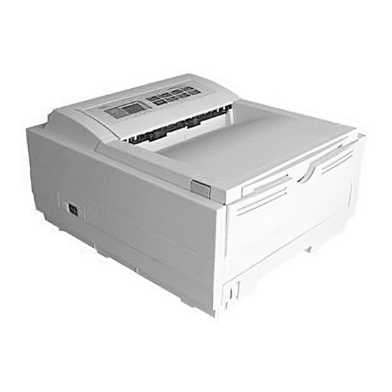
Oki okipage 10ex led page printer
Hide thumbs
Also See for OKIPAGE 10ex:
- Maintenance manual (340 pages) ,
- Troubleshooting manual (143 pages) ,
- Setup manual (16 pages)

Related Manuals for Oki OKIPAGE 10ex

Summary of Contents for Oki OKIPAGE 10ex
- Page 1 OKIPAGE 10ex LED Page Printer Maintenance Manual ODA / OEL / INT Rev.1 98. 11. 19 All specifications are subject to change without notice.
- Page 2 PREFACE This Maintenance Manual describes the field maintenance methods for OKIPAGE 10ex LED Page Printers. This manual is written for use by the maintenance personnel. Please note that you should refer to the Printer Handbook and Printer Setup for the handling and operating methods of the equipment.
-
Page 3: Table Of Contents
CONTENTS 1. CONFIGURATION ..................1 - 1 1.1 System Configuration ................ 1 - 1 1.2 Printer Configuration ................1 - 3 1.3 Optional Configuration ............... 1 - 4 1.4 Specification ..................1 - 6 1.5 Safety Standards ................1 - 8 1.5.1 Certification Label .................. - Page 4 3.3.22 Transformer ..................... 3 - 28 3.3.23 Power Supply/Sensor Board and Contact Assy ........3 - 29 3.3.24 Cassette Guide L Assy ................3 - 30 3.3.25 Cassette Guide R Assy ................3 - 31 3.3.26 Spacer Bearing (L/R) ................3 - 32 4.
-
Page 5: Configuration
1. CONFIGURATION... -
Page 6: System Configuration
CONFIGURATION System Configuration OKIPAGE 10ex consists of control and engine blocks in the standard configuration, as shown in Figure 1-1. In addition, the options marked with asterisk(*) are available. 1 - 1... - Page 7 Operator Panel Engine Unit Paper Cassette Face Up Stacker *High Capacity Second Paper Paper Feeding Mechanism Feeder (First Tray Unit) Face *Multi Purpose Down Feeder Stacker Electrophotographic Processing Unit Power Supply and Sensor Board Centronics Main Control Board Memory* * : Optional Expansion Board 1 DRAM SIMM Socket 1 Flash SIMM Socket...
-
Page 8: Printer Configuration
Printer Configuration The printer unit consists of the following hardware components: • Electrophotographic Processor • Paper Feeder • Controller • Operator Panel • Power Supply Unit The printer unit configuration is shown in Figure 1-2. Upper cover Operator panel assy Toner-cartridge(Type 5) (consumable) Stacker assy... -
Page 9: Optional Configuration
Optional Configuration The options shown below are available for use with OKIPAGE 10ex. These are available separately from the printer unit. (1) High Capacity Second Paper Feeder (2) Multi Purpose Feeder (3) 1MB Memory Expausion Board 1 - 4... - Page 10 (4) RS-232C Serial Interface Board (5) DRAM SIMM Memory DRAM SIMM memory is available with memory of 1MB (min.) to 32MB (max.). The access time of SIMM memories are 60ns, 70ns, 80ns, and 100ns. (6) Flash SIMM Flash SIMM is available with memory of 4MB and 8MB. 1 - 5...
-
Page 11: Specification
Specification (1) Type Desktop (2) External dimensions Height 7.9” (200 mm) Width 13.0” (330 mm) Depth 15.6” (395 mm) (3) Weight Approx. 10 kg (4) Developing method Dry electrophotography Exposing method LED stationary head (5) Paper used <Type> • Standard paper –... - Page 12 (8) Paper delivery method Face down/face up (9) Resolution 600 x 600 dots/inch 600 x 1200 dots/inch (10) Power input 120 VAC + 5.5%, -15% 230 VAC ± 10% (11) Power consumption Peak: Approx. 460W Typical operation: Approx. 215W Idle: Approx.
-
Page 13: Safety Standards
Safety Standards 1.5.1 Certification Label The safety certification label is affixed to the printer in the position described below. INT AC : 230V model ODA AC : 120V model ODA AC : 230V model 1.5.2 Warning Label The warning labels are affixed to the sections which may cause bodily injury. Follow the instructions on warning labels during maintenance. -
Page 14: Warning/Caution Marking
1.5.3 Warning/Caution Marking The following warning and caution markings are made on the power supply/sensor board. WARNING AVERTISSEMENT ADVERTENCIA CAUTION HEATSINK AND TRANSFORMER ATTENTION ATENCÃO PRESENT RISK OF ELECTRIC SHOCK CUIDADO CUIDÃDO TEST BEFORE TOUCHING * No fuse is mounted here for 200V series ENGLISH Heatsink and transformer core present risk of electric shock. -
Page 15: Operation Description
OPERATION DESCRIPTION... - Page 16 OPERATION DESCRIPTION OKIPAGE 10ex consists of a main control board, a power supply/sensor board, an operator panel, an electrophotographic process mechanism, and revision for illumination of LED head. The main control board receives data via the host I/F, it then decodes, edits and stores the data in memory.
- Page 17 Paper sensor Toner supply roller Outlet sensor Cleaning roller Thermistor Paper out sensor Fusing temperature control circuit Heater drive Toner low sensor Heater circuit transformer Filter circuit AC IN Figure 2-1 OKIPAGE 10ex Block Diagram 2 - 2...
-
Page 18: Main Control Board
Main Control Board The main control board consists of a single chip CPU, two program/font ROMs, four DRAMs, an EEPROM, a host interface circuit, and a mechanism driving circuit. (1) Single chip CPU The single chip CPU is a custom CPU (32-bit internal bus, 32-bit external bus, 28.24-MHz clock, with input frequency from a 7.06-MHz clock) which incorporates the RISC CPU and its peripheral devices, and has the following functions: Built-in device... -
Page 19: Power Supply/Sensor Board
Power Supply/Sensor Board The power supply/sensor board consists of an AC filter circuit, a low voltage power supply circuit, a high voltage power supply circuit, heater drive circuit, and photosensors. (1) Low Voltage Power Supply Circuit This circuit generates the following voltages. Output voltage +5 V Logic circuit supply voltage... - Page 20 The sensor layout diagram is shown in Figure 2-2. Exit roller Outlet sensor Heat roller Transfer roller Paper sensor Toner Inlet sensor sensor 2 Registration roller Paper end sensor Hopping roller Inlet sensor 1 Figure 2-2 Sensor Function Sensing state Inlet sensor 1 Detects the leading part of the paper and gives the monitor timing ON: Paper exists.
-
Page 21: Electrophotographic Process
Electrophotographic Process 2.3.1 Electrophotographic Process Mechanism This mechanism actuates the printing of image data supplied by the main control board on the paper by electrophotographic process. The layout of the electrophotographic process mechanism is shown in Figure 2-3. 2 - 6... - Page 22 Figure 2-3 2 - 7...
- Page 23 (1) Image Drum Unit The image drum unit consists of a sensitive drum, a charger, and a developer. The unit forms a toner image on the sensitive drum, using a electrostatic latent image formed by the LED head. (2) Registration Motor The registration motor is a pulse motor of 48 steps/rotation with two-phase excitement by the signal from the main control board.
- Page 24 2.3.2 Electrophotographic Process The electrophotographic processing is outlined below. The electrophotographic printing process is shown in Figure 2-4. 1 Charging The surface of the image drum is charged uniformly with a negative charge by applying the negative voltage to the charge roller. 2 Exposure Light emitted from the LED head irradiates the negatively charged surface of the image drum.
- Page 25 Figure 2-4 2 - 10...
- Page 26 Figure 2-5 2 - 11...
-
Page 27: Process Operation Descriptions
2.3.3 Process Operation Descriptions (1) Hopping and Feeding Hopping and feeding motions are actuated by a single registration motor in the mechanism as shown below: Registration motor Idle gear Registration roller Hopping roller Motor gear Registration gear Hopping gear The registration motor turning in direction "a" drives the hopping roller. The registration motor turning in direction "b"... - Page 28 Hopping 1 For hopping, the registration motor turns in direction "a" (clockwise direction) and drives the hopping roller to advance the paper until the inlet sensor turns on (in this case, the registration gear also turns, but the registration roller is prevented from turning by the one-way bearing).
- Page 29 (2) Charging Charging is actuated by the application of the DC voltage to the charge roller that is in contact with the image drum surface. Power Charge roller supply Image drum The charge roller is composed of two layers, a conductive layer and a surface protective layer, both having elasticity to secure good contact with the image drum.
- Page 30 (3) Exposure Light emitted by the LED head irradiates the image drum surface with a negative charge. The surface potential of the irradiated portion of the image drum drops, forming an electrostatic latent image associated with the image signal. LED head LED head Charge roller Power...
- Page 31 The image roller surface is charged to about –750 V by the contact charge of the charge roller. When the light from the LED head irradiates the image drum surface, the light energy generates positive and negative carriers in the CGL. The positive carriers are moved to the CTL by an electrical field acting on the image drum.
- Page 32 (4) Developing Toner is attracted to the electrostatic latent image on the image drum surface, converting it into a visible toner image. Developing takes place through the contact between the image drum and the developing roller. 1 As the toner supply roller rotates while rubbing on the developing roller, a friction charge is generated between the developing roller and the toner, allowing the toner to be attracted to the developing roller (the developing roller surface is charged positive and the toner, negative).
- Page 33 Note: The bias voltage required during the developing process is supplied to the toner supply roller and the developing roller, as shown below. –500 VDC is supplied to the toner supply roller, –265 VDC to the developing roller. Connected and bias supplied when the cover is closed.
- Page 34 (5) Transfer The transfer roller is composed of conductive sponge material, and is designed to get the image drum surface and the paper in a close contact. Paper is placed over the image drum surface, and the positive charge, opposite in polarity to that of the toner, is applied to the paper from the reverse side.
- Page 35 (6) Fusing When the transfer is completed, the toner image is fused to the paper by heat and pressure as the paper with unfused toner image passes between the heater roller and the back-up roller. The heater roller with Teflon coating incorporates a 400W heater (Halogen lamp), which generates heat.
- Page 36 (7) Cleaning When the transfer is completed, the residual toner left on the image drum is attracted to the cleaning roller temporarily by static electricity, and the image drum surface is cleaned. Image drum Cleaning roller Power supply Transfer roller (8) Cleaning of rollers The charge, transfer and cleaning rollers are cleaned for the following cases: •...
-
Page 37: Revision Of Led Head Illumination
2.3.4 Revision of LED Head Illumination An LED correcting head, which is capable of correcting the illumination of the LED for each dot, is being used in this printer. LED illumination correction function of 16 steps is carried out by using an EEPROM which is installed in the LSI that maintains the LED illumination correction values, and an LED correction drivers (MSM6731BWAF or MSM6732BWAF) together as a pair. - Page 38 The printing operation timing chart is shown below. Normal Mode Printing Timing Chart CLOCKI LOADI DATAI3~0 STRB1I-N STRB2I-N STRB3I-N STRB4I-N First line printing data sent Second line printing data sent First line printing The printing operation is carried out in normal mode. Under ordinary circumstances such as when the power is turned on or when LOADI signal level is low, the normal mode is enabled.
- Page 39 The mode setting timing chart during illumination correction is shown below. Illumination Correction Mode Setting Timing Chart 50ns 50ns 100ns min 200ns min 100ns min CLOCKI LOADI DATAI0 D4 D3 D2 D1 D0 STRB1I-N STRB2I-N STRB3I-N STRB4I-N Mode setting Mode enabled Mode set The mode setting is carried out in the following manner.
- Page 40 The LED driver (MSM6731BWAF) corrects the LED illumination by controlling the LED current. The LED illumination can be set in 16 steps, with 7 steps in the direction of illumination increase in relation to the standard value, and 8 steps in the direction of decrease. For this reason, the LED correction data is a 4-bit data for each dot.
-
Page 41: Paper Jam Detection
Paper Jam Detection The paper jam detection function monitors the paper condition when the power is turned on and during printing. When any of the following conditions arises, this function interrupts the printing process. If any of the following errors is encountered, printing can be recovered by removing the jammed paper (by opening the upper cover, removing the jammed paper and closing the upper cover). - Page 42 Paper Feed Check List Error Type of error Monitor Standard value Plus Minus Paper feed error Hopping start In sensor on 72.0 36.0 – Paper feed jam In sensor on Write sensor on 20.0 22.0 – Paper feed jam Write sensor on Out sensor on 140.5 25.0...
-
Page 43: Cover Open
Cover Open When the stacker cover is opened, the cover open microswitch on the power supply/sensor board is turned off to cut +5V supply to the high voltage power supply circuit. This results in the interruption of all high-voltage outputs. At the same time, the CVOPN signal is sent to the main control board to notify that the microswitch is off, and the main control board carries out the cover open process. -
Page 44: Toner Low Detection
Toner Low Detection • Device The Toner Low Detection device consists of a stirring gear which rotates at a constant rate, a stirring bar and a magnet on the stirring bar. The stirring bar rotation is driven by the link to the gouged portion in the stirring gear. - Page 45 TONER FULL state 160 ms < t1 < 0.8 sec TNRSNS-N 2.63 sec. TONER LOW state t1 > 0.8 sec. TNRSNS-N 2.63 sec. • When the Toner Low state is detected 2 times consecutively, Toner Low is established. • When the Toner Full state is detected 2 times consecutively, Toner Low is cancelled. •...
-
Page 46: Parts Replacement
PARTS REPLACEMENT... -
Page 47: Precautions For Parts Replacement
PARTS REPLACEMENT The section explains the procedures for replacement of parts, assemblies, and units in the field. Only the disassembly procedures are explained here. For reassembly, reverse the disassembly procedure. Precautions for Parts Replacement (1) Before starting to replace parts, remove the AC cord and interface cable. Remove the AC cord in the following sequence: Turn off (“o”) the power switch of the printer Disconnect the AC inlet plug of the AC cord from the AC receptacle. - Page 48 [Service Tools] The tools required for field replacement of printed circuit boards, assemblies and units are listed in Table 3-1. Table 3-1 Service Tools Service Tools Q' ty Application Remarks No. 1-100 Philips screwdriver 2~2.5 mm screws No. 2-100 Philips screwdriver 3~5 mm screws No.
-
Page 49: Parts Layout
Parts Layout This section explains the layout of main components of the equipment. [Lower base unit] Pulse motor Stacker cover assy (main/drum) Eject roller assy View A Back-up roller Pulse motor Transfer roller (registration) Diselectrification bar Registration roller Spacer bearing R Fusing unit Spacer bearing L Lower base unit... - Page 50 [Upper cover unit] Upper cover Figure 3-2 3 - 4...
- Page 51 [Base unit] Operator panel assy Power supply/ sensor board Transformer Face up stacker assy DC fan assy Main control board Cassette guide (R) Cassette guide(L) Paper cassette Figure 3-3 3 - 5...
-
Page 52: How To Change Parts
How to Change Parts This section explains how to change parts and assemblies listed in the disassembly diagram below. In the parts replacement procedure, those parts marked with the part number inside with white letters are RSPL parts. Printer unit Upper cover assy Operator panel assy Face up stacker assy... -
Page 53: Upper Cover Assy
3.3.1 Upper Cover Assy (1) With the power switch turned off, unplug the AC power cord from the outlet. (2) Disconnect the interface cable 1. (3) Press the knobs 2 on left and right sides and open the stacker cover assy 3. (4) Take out the image drum unit 4. -
Page 54: Ic Card Cover
3.3.2 IC Card Cover (1) Open the IC card cover 1, press it from both sides at the hinges in the directions of arrows shown below and remove it. 3 - 8... -
Page 55: Led Head
3.3.3 LED Head (1) Press the knobs on left and right sides and open the stacker cover assy 1. (2) Open the hook section on the left side of the stacker cover and remove the LED head 2. Note: • Be sure not to touch directly or push on the SLA part of the LED head. -
Page 56: Operator Panel Assy
3.3.4 Operator Panel Assy (1) Unlock two latches on the upper cover from the rear side, lift the operator panel assy 1 from the back and remove it. (2) Remove the Sumi card (operator panel) 2 from the connector (CN1) 3. Note : You can remove the operator panel assy while the upper cover installed on the unit. -
Page 57: Lower Base Unit
3.3.5 Lower Base Unit (1) Remove the upper cover assy (see 3.3.1). (2) Remove the operator panel assy (see 3.3.4). (3) Remove the face up stacker assy (see 3.3.8). (4) Remove the connecting cables 2 and 3 of the pulse motors from the connectors (DM, RM) of the M5B-PCB 1. -
Page 58: Pulse Motor (Main/Drum)
3.3.6 Pulse Motor (Main/Drum) (1) Remove the upper cover assy (see 3.3.1). (2) Remove the lower base unit (see 3.3.5). (3) Remove two screws 1 and remove the pulse motor (main/drum) 2 from the motor bracket View A View A 3 - 12... -
Page 59: Pulse Motor (Registration)
3.3.7 Pulse Motor (Registration) (1) Remove the upper cover assy (see 3.3.1). (2) Remove the lower base unit (see 3.3.5). (3) Remove two screws 1 and remove the pluse motor (registration) 2 from the motor bracket View A View A 3 - 13... -
Page 60: Face Up Stacker Assy
3.3.8 Face Up Stacker Assy (1) Remove the upper cover assy (see 3.3.1). (2) Remove the operator panel assy (see 3.3.4). (3) Remove the screw 1 and remove the Sumi card (operator panel cable) 2 off the latch section of face up stacker 4. Remove both the shield plate 3 and face up stacker 4 together. -
Page 61: Eject Roller Assy
3.3.9 Eject Roller Assy (1) Remove the upper cover assy (see 3.3.1). (2) Remove the operator panel assy (see 3.3.4). (3) Remove the face up stacker assy (see 3.3.8). (4) Remove the lower base unit (see 3.3.5). (5) Disengage the eject roller assy 1 from the lower base 2 by pressing the latch section of the eject roller assy 1 in the direction of the arrow shown below, and remove the eject roller assy LATCH 3 - 15... -
Page 62: 3.3.10 Motor Assy
3.3.10 Motor Assy (1) Remove the upper cover assy (see 3.3.1). (2) Remove the operator panel assy (see 3.3.4). (3) Remove the face up stacker assy (see 3.3.8). (4) Remove the lower base unit (see 3.3.5). (5) Stand the lower base unit on its side as shown, and unlock two latches, then remove the motor assy 1. -
Page 63: Hopping Roller Shaft Assy
3.3.11 Hopping Roller Shaft Assy (1) Remove the upper cover (see 3.3.1). (2) Remove the operator panel assy (see 3.3.4). (3) Remove the face up stacker assy (see 3.3.8). (4) Remove the lower base unit (see 3.3.5). (5) Remove the motor assy (see 3.3.10). (6) With the lower base unit 1 standing on its side, remove the one-way clutch gear 2 and the bearing (A) 3. -
Page 64: Stacker Cover Assy
3.3.12 Stacker Cover Assy (1) Remove the upper cover assy (see 3.3.1). (2) Remove the operator panel assy (see 3.3.4). (3) Remove the face up stacker assy (see 3.3.8). (4) Remove the reset lever R 1. (5) Detach the reset spring 2 from the lower base unit 3, turn the reset lever L 4 in the direction of arrow until it stops, and remove it in the direction of arrow (6) Unlock two latches of the lower base unit 3, then remove the stacker cover assy 5. -
Page 65: Registration Roller
3.3.13 Registration Roller (1) Remove the upper cover (see 3.3.1). (2) Remove the operator panel assy (see 3.3.4). (3) Remove the face up stacker assy (see 3.3.8). (4) Remove the lower base unit (see 3.3.5). (5) Remove the motor assy (see 3.3.10). (6) With the lower base unit standing on its side, remove the one-way clutch gear 1. -
Page 66: 3.3.14 Roller Transfer Assy
3.3.14 Roller Transfer Assy (1) With the power switch turned off, unplug the AC cord from the outlet. (2) Open the stacker cover. (3) Release the roller transfer assy 1 by unlocking the latch of the main unit (never apply excessive force when unlocking the latch). -
Page 67: 3.3.15 Fusing Unit
3.3.15 Fusing Unit (1) Remove the upper cover (see 3.3.1). (2) Remove the operator panel assy (see 3.3.4). (3) Remove the face up stacker assy (see 3.3.8). (4) Remove the stacker cover assy (see 3.3.12). (5) Remove four screws 1, lift and remove the fusing unit 2. Caution: Fusing unit may be hot. -
Page 68: 3.3.16 Back-Up Roller
3.3.16 Back-up Roller (1) Remove the fusing unit assy (see 3.3.15). (2) Lift the left side of the back-up roller 1, and pull it out to the left side (at this time, two bushings (back-up) 2 and the bias springs (back-up) 3 will also come off). 3 - 22... -
Page 69: Sensor Plate (Inlet)
3.3.17 Sensor Plate (Inlet) (1) Remove the upper cover (see 3.3.1). (2) Remove the operator panel assy (see 3.3.4). (3) Remove the face up stacker assy (see 3.3.8). (4) Remove the lower base unit (see 3.3.5). (5) Press the clamps of three sensor plates (inlet and paper) 1, and remove them by pressing them upward from the bottom. -
Page 70: Sensor Plate (Outlet)
3.3.18 Sensor Plate (Outlet) (1) Remove the upper cover assy (see 3.3.1). (2) Remove the operator panel assy (see 3.3.4). (3) Remove the eject roller assy (see 3.3.9). (4) Remove the face up stacker assy (see 3.3.8). (5) Remove the lower base unit (see 3.3.5). (6) Remove the fusing unit assy (see 3.3.15). -
Page 71: Manual Feed Guide Assy
3.3.19 Manual Feed Guide Assy (1) Remove the upper cover assy (see 3.3.1). (2) Open the manual feed guide assy 1, and release the engagement on both sides with the main unit by carefully bending the manual feed guide assy 1. Note : When remounting, verify the proper the engagements as shown in the diagram. -
Page 72: Sensor Plate (Paper Supply)
3.3.20 Sensor Plate (Paper Supply) (1) Remove the upper cover assy (see 3.3.1). (2) Remove the operator panel assy (see 3.3.4). (3) Remove the face up stacker assy (see 3.3.8). (4) Remove the lower base unit (see 3.3.5). (5) Press the clamps of the sensor plate (paper supply) 1 to unlock the latch, and remove it from the base plate 2. -
Page 73: 3.3.21 M5B-Pcb
3.3.21 M5B-PCB (1) Remove the upper cover assy (see 3.3.1). (2) Remove the operator panel assy (see 3.3.4). (3) Remove the face up stacker assy (see 3.3.8). (4) Remove the lower base unit (see 3.3.5). (5) Remove the connector (2NDTRAY) 6. (6) Remove three screws 1. -
Page 74: Transformer
3.3.22 Transformer (1) Remove the upper cover assy (see 3.3.1). (2) Remove the operator panel assy (see 3.3.4). (3) Remove the face up stacker assy (see 3.3.8). (4) Remove the connectors (CN1 and CN2). (5) Remove two screws 1, and remove the transformer 2. Note : When reinstalling the transformer, be sure to lay the AC and transformer’s primary side cables under the divider (see view A diagram below). -
Page 75: 3.3.23 Power Supply/Sensor Board And Contact Assy
3.3.23 Power Supply/Sensor Board and Contact Assy (1) Remove the upper cover assy (see 3.3.1). (2) Remove the lower base unit (see 3.3.5). (3) Remove the M5B-PCB (See 3.3.21). (4) Remove the transformer (see 3.3.22). (5) Remove the AC inlet 1 from the base plate 2. (6) Remove the screw 3 and remove the grounding (earth) wire 4. -
Page 76: 3.3.24 Cassette Guide L Assy
3.3.24 Cassette Guide L Assy (1) Remove the paper cassette. (2) Remove the upper cover assy (see 3.3.1). (3) Remove the lower base unit (see 3.3.5). (4) Remove the M5B-PCB (see 3.3.21). (5) Remove the transformer (see 3.3.22). (6) Remove the power supply/sensor board (see 3.3.23). (7) Remove two screws 1, and remove the guide rails 2. -
Page 77: 3.3.25 Cassette Guide R Assy
3.3.25 Cassette Guide R Assy (1) Remove the paper cassette. (2) Remove the upper cover assy (see 3.3.1). (3) Remove the lower base unit (see 3.3.5). (4) Remove the M5B-PCB (see 3.3.21). (5) Remove two screws 1, and remove the guide rails 2. (6) Remove the screw 3, and remove the cassette guide R 4 by shifting it in the direction of arrow. -
Page 78: Spacer Bearing (L/R)
3.3.26 Spacer Bearing (L/R) (1) Remove the back-up roller (see 3.3.16). (2) Remove spacer bearing (L/R) with a tip of screw driver. Spacer bearing L Spacer bearing R 3 - 32... -
Page 79: Adjustment
ADJUSTMENT... -
Page 80: Maintenance Modes And Functions
ADJUSTMENT This chapter provides explanations concerning the adjustment necessary when replacing a part. The adjustment is made by changing the parameter value set in EEPROM on the main control board. The parameter can be set by the key operation from the operator panel. This printer has three kinds of maintenance modes, and it is necessary to select one of the modes when replacing any parts. -
Page 81: Engine Maintenance Mode
4.1.3 Engine Maintenance Mode Note: This mode is used only by maintenance personnel, and it should not be released to the end users. (1) To enter into the engine maintenance mode, turn the power on while holding ENTER and FORM FEED keys down. (2) Functions of this mode are selected by the menu. -
Page 82: Eeprom Initialization
4.1.4 EEPROM initialization The corresponding are of the EEPROM is initialized for each event as shown Table 4-1. Talbe 4-1 EEPROM Initial Setting Range EEPROM area No Event User maintenance menu reset System main- tenance EEPROM reset Engine maintenance Note2) Note2) engine reset Firm revision check error at power-on... -
Page 83: Adjustment When Replacing A Part
Adjustment When Replacing a Part Adjustment is necessary when replacing any of the following parts. Part Replaced Adjustment LED Head Set the LED head drive time. Image Drum Cartridge Reset the image drum counter (refer to User's manual). Main Control Board EEPROM data Upload / Download 4.2.1 Setting of LED Head Drive Time... -
Page 84: Setting Of Led Head Drive Time
• Setting of LED Head Drive Time Drive time of the LED head is set by setting the parameter of drive time of EEPROM according to the luminous intensity marking on the LED head. a. Corresponding table of luminous intensity marking and drive time parameter Luminous intensity Luminous intensity Drive time parameter... - Page 85 c. Setting Example: Method for setting the parameter to 19 (for a case where the previous parameter setting was 8). Operation LCD display after operation Turn the POWER switch ENG MNT on while holding the FORM FEED and ENTER keys down. LED HEAD Displays previous Press the MENU key...
-
Page 86: Uploading/Downloading Eeprom Data
4.2.2 Uploading/Downloading EEPROM data When the controller printed circuit board is replaced, the contents of the old EEPROM shall be copied to the new EEPROM on the new board to preserve customer settings. For the purpose, use the EEPROM operation on the Option of the Maintenance Utility. To copy follow the steps below. -
Page 87: Periodical Maintenance
PERIODICAL MAINTENANCE... -
Page 88: Periodical Replacement Parts
PERIODICAL MAINTENANCE Periodical Replacement Parts The parts are to be replaced periodically as specified below: Part name Condition for replacement Cleaning Remarks • Toner cartridge(Type 5) About 2,000 sheets of paper have been printed. • LED head Consumables • Image drum cartridge About 20,000 sheets of paper have been printed. - Page 89 (1) Set the LED head cleaner to the LED lens array as shown in the figure, then slide the cleaner back and forth horizontally several times to clean the head. Note: Gently press the LED head cleaner onto the LED lens array. LED head clean pad LED lens array (2) Throw the cleaner pad away.
- Page 90 5.2.2 Cleaning Page Function There is a charge roller cleaning function with this printer, which can be executed by the user. (1) While the printer is in off-line mode, press both keys simultaneously for at least 2 seconds. The printer enters the cleaning mode. (2) The LCD displays "CLEANING"...
-
Page 91: Troubleshooting Procedures
TROUBLESHOOTING PROCEDURES... -
Page 92: Troubleshooting Tips
TROUBLESHOOTING PROCEDURES Troubleshooting Tips (1) Check the troubleshooting section in the Printer Handbook. (2) Gather as much information about the situation as possible. (3) Inspect the equipment under the conditions close to those in which the problem had occurred. Points to Check before Correcting Image Problems (1) Is the printer being run in proper ambient conditions? (2) Are supplies (toner) and routine replacement part (image drum cartridge) being replaced properly? -
Page 93: Preparation For Troubleshooting
Preparation for Troubleshooting (1) Operator panel display The failure status of the printer is displayed by the liquid crystal display (LCD) of the operator panel. Take proper corrective action as directed by messages which are being displayed on the LCD. <For ODA>... -
Page 94: Troubleshooting Flow
Troubleshooting Flow Should there be a problem with the printer, carry out troubleshooting according to the following procedure flow: Problems Carry out a detailed Problems Troubleshoot from the LCD troubleshooting with the indicated by LCD status message list. troubleshooting chart. message See Section 6.5.1. - Page 95 6 - 4...
- Page 96 6 - 5...
- Page 97 6 - 6...
- Page 98 6 - 7...
- Page 99 6 - 8...
- Page 100 6 - 9...
- Page 101 6 - 10...
- Page 102 6 - 11...
- Page 103 6 - 12...
-
Page 104: Lcd Message Troubleshooting
6.5.2 LCD Message Troubleshooting If the problems cannot be corrected by using the LCD status message/problem list, follow the troubleshooting flowcharts given here to deal with them. Trouble Flowchart number The printer does not work normally after the power is turned on. Jam alarm Paper input jam Paper feed jam... -
Page 105: The Printer Does Not Work Normally After The Power Is Turned On
The printer does not work normally after the power is turned on. • Turn the power off, then back on. • Is all black message being displayed by the LCD display? • No Is the AC cord being connected properly? •... - Page 106 • Yes • Take the measurement of the following voltage readings at connector CN2 on the power supply/sensor board: Voltage between Pins 1 and 3: ... about 40 V AC Voltage between Pins 5 and 6: ... about 9.2 V AC Are the voltages within the normal range? •...
-
Page 107: Paper Input Jam
[JAM error] Paper input jam • Does the JAM error occur when the power is turned on? • Yes Is the paper at the inlet sensor? • Yes Remove the paper. • No Is the operation of the inlet sensor plate normal (moves freely when it is touched)? •... -
Page 108: Paper Feed Jam
[JAM error] Paper feed jam • Does the paper feed jam occur when the power is turned on? • Yes Is the paper on the paper sensor plate? • Yes Remove the paper. • No Is the operation of the paper sensor plate normal (moves freely when it is touched)? •... -
Page 109: Paper Exit Jam
2-2-a • No Check the gears (transfer roller gear, idle gear and reduction gear). • Yes Is the fusing unit being installed properly? • No Install the fusing unit properly. • Yes Is the image drum cartridge being set properly? •... -
Page 110: Paper Size Error
Paper size error • Is paper of the specified size being used? • No Use paper of the specified size. • Yes Are inlet sensor plates 1 and 2 operating properly (moves freely when they are touched)? • No Replace the inlet sensor plate or clean the inlet sensor on the power supply/ sensor board. -
Page 111: Fusing Unit Error
Fusing unit error (ERROR 71) (ERROR 72) (ERROR 73) • Turn the power off, then back on again. • Yes Is the thermistor open or shorted? Measure the resistance between thermistor contacts (heater contacts 120V/3Ω or 240V/10Ω, and thermistor contacts 220KΩ at room temperature) (see Figure 6-2 or Section 7.3). -
Page 112: Fan Error
Synchronous serial I/O error (ERROR 74) or I/F timeout between printer and optional tray (ERROR 81) • Is an option tray (High Capacity Second Paper Feeder or Power Envelope Feeder) being used? • Yes Is the cable between the main control board and the optional tray being connected properly? •... -
Page 113: Image Troubleshooting
6.5.3 Image Troubleshooting Procedures for troubleshooting for abnormal image printouts are explained below. Figure 6-3 below shows typical abnormal images. Problem Flowchart number Images are light or blurred entirely (Figure 6-3 Dark background density (Figure 6-3 Blank paper is output (Figure 6-3 Black vertical belts or stripes (Figure 6-3 Cyclical defect (Figure 6-3 Prints voids... - Page 114 Images are light or blurred entirely. • Is toner low (is the TONER LOW message displayed)? • Yes Supply toner. • No Is paper of the specified grade being used? • No Use paper of the specified grade. • Yes Is the lens surface of the LED head dirty? •...
- Page 115 Dark background density • Has the image drum been exposed to external light? • Yes Install the image drum in the printer and wait about 30 minutes. • No Perform the cleaning page function (see Section 5.2.2). • Has the problem been solved? •...
- Page 116 Blank paper is output. • Is the LED head being connected properly (check the HEAD1 and HEAD2 connectors on the main control board and PC connector on the LED head)? • No Connect the LED head properly or replace the head cable(s). •...
- Page 117 Black vertical belts or stripes • Perform the cleaning page function (see Section 5.2.2). • Has the problem been solved? • Yes End. • No Replace the image drum cartridge. • Has the problem been solved? • Yes Note: After replacing the image drum cartridge, set the printer to the user maintenance mode by turning the power on while pressing the MENU key, and reset the drum counter (see Printer Handbook).
- Page 118 Cyclical defect Frequency Remedy Image drum 3.71" (94.2mm) Replace or clean the image drum cartridge. Developing roller 1.86" (47.12mm) Replace the image drum cartridge. Toner supply roller 2.96" (75.27mm) Replace the image drum cartridge. Charging roller 1.21" (30.63mm) Replace the image drum cartridge. Cleaning roller 0.93"...
- Page 119 Prints voids • Is the contact plate of the transfer roller in proper contact with the power supply/sensor board (see Figure 6-5)? • No Adjust the contact plate so that it touches the power supply/sensor board and the shaft of the transfer roller properly. •...
- Page 120 Poor fusing (images are blurred or peels off when the printed characters and images on the paper are touched by hand) • Is paper of the specified grade being used? • No Use paper of the specified grade. • Yes Is the tension between the back-up roller (7.52kg) and the surface of back-up roller normal? •...
- Page 121 White vertical belts or streaks • Are the LED lens dirty? • Yes Clean the LED lens. • No Is the contact plate of the transfer roller in proper contact with the power supply/sensor board (see Figure 6-5)? • No Adjust the contact plate to make a proper contact with the power supply/sensor board.
- Page 122 Figure 6-4 6 - 31...
- Page 123 Contact plate for transfer roller Power supply/sensor board Contact Figure 6-5 6 - 32...
-
Page 124: Wiring Diagram
WIRING DIAGRAM... -
Page 125: Interconnect Signal Diagram
WIRING DIAGRAM Interconnect Signal Diagram 7 - 1... -
Page 126: Pcb Layout And Connector Signal List
PCB Layout and Connector Signal List (1) Main Control Board (M5B-PCB) Printer front side OPTION HEAD1 HEAD2 OPTION CENT LED Head Operator panel Printer front side Contact face Contact face Printer front side 6 – 1 14 – 1 12 – 1 7 - 2... - Page 127 (2) Power Supply/Sensor Board TR OUT * In case of 200V series, there is no F2 on the power supply/sensor board. 7 - 3...
- Page 128 • FAN Connector Pin Assignment (To fan motor) PIN NO. I/O* Signal Description FANPOW Power supply for fan driving Opening Ground FANALM-N Fan alarm • DM Connector Pin Assignment (To main/drum motor) PIN NO. I/O* Signal Description DMPH1-P Coil 1-N DMPH1-N Coil 1-P DMPH2-P...
- Page 129 • RM Connector Pin Assignment (To registration motor) PIN NO. I/O* Signal Description RMPH1-P Coil 1-N RMPH1-N Coil 1-P RMPH2-P Coil 2-P RMPH2-N Coil 2-N * I: In O: Out Excitation sequence Step No. PIN NO. Line Color Yellow Black Orange Brown Rotary direction...
- Page 130 • HEAD1 Connector Pin Assignment (To LED head) PIN NO. I/O* Signal Description HDSTB4-N Strobe 4 HDSTB3-N Strobe3 HDSTB2-N Strobe 2 HDSTB1-N Strobe 1 HDDLD-P Load +3.3V +3.3V power supply for LED driving HDD1-P Data 1 HDD0-P Data 0 OVLED Ground for LED HDD3-P Data 3...
- Page 131 • PANEL Connector Pin Assignment (To operator panel) PIN NO. I/O* Signal Description PLD-N Load Logic groud PDATAOUT-P Data output PDATAIN-P Data input +5V power supply PSCLK-N Clock * I: In O: Out C: Common • ENVELOPE Connector Pin Assignment (To option feeder I/F) PIN NO.
- Page 132 7 - 8...
- Page 133 7 - 9...
- Page 134 7 - 10...
-
Page 135: Resistance Check
Resistance Check 7 - 11... - Page 136 7 - 12...
-
Page 137: Short Plug Setting
Short Plug Setting (1) Main Control Board (M5B-PCB) • Short plug settings Short plug Plug setting Description Factory setting Provided Debug mode Not provided Not provided Normal 2-3 Short +5 V is supplied to Pin 18 of Centronics parallel I/F connector. 2-3 Short 1-2 Short +5 V is not supplied to Pin 18 Centronics parallel I/F connector. -
Page 138: Parts List
PARTS LIST... - Page 139 PARTS LIST Figure 8-1 Lower Base Unit 8 - 1...
- Page 140 Table 8-1 Lower Base Unit (1/2) Name/Rating Part No. Remarks ODA Part No. Hopping roller shaft 3PP4083-6020P001 51112601 Bearing 4PP4083-6022P002 51607402 Hopping roller one-way clutch gear 4PB4083-6024P001 51228901 Registration roller 3PB4083-6030P001 53342401 Bearing (registration) 4PP4083-6031P001 51607501 Roller-Transfer B Assy 40437801 Bearing TR 40438001 Back-up roller...
- Page 141 Table 8-1 Lower Base Unit (2/2) Name/Rating Part No. Remarks ODA Part No. FG plate (O.P.) 4PP4083-7663P001 Hopping roller rubber 4PB4122-1280P001 Diselectritication Film 3PB4083-6089P001 LED Contact 4PP4083-6173P001 Washer C 4PP4120-1210P001 Washer B 4PP4120-1209P001 Spacer-Bearing R 40392801 Spacer-Bearing L 40392901 Bias spring A 4PP4083-6065P001 Special parts for envelope * * This part is countermesur for envelope wrinkle and common part to bias spring A in OL400e.
- Page 142 Figure 8-2 Upper cover unit 8 - 4...
- Page 143 Table 8-2 Upper cover unit Name/Rating Part No. Remarks ODA Part No. Upper cover 1PP4128-1133P001 53070301 IC card cover 2PP4128-1155P001 53069301 Cover-Lid 40104801 8 - 5...
- Page 144 Figure 8-3 Base unit 8 - 6...
- Page 145 Table 8-3 Base unit Name/Rating Part No. Remarks ODA Part No. Base plate (adhension) 2PP4083-7672G001 809A3000001~ 51012901 810AXXXXXXX Plate Assy-Base 40919401 811AXXXXXXX~ Cassette guide (L) assy 3PP4083-7670G001 51011201 Cassette guide (R) assy 3PP4083-7671G001 51011301 Sensor plate (paper supply) 4PP4083-7667P001 51011401 Insulator 3PB4083-6144P001 51709401...
-
Page 146: Appendix A Rs-232C Serial Interface (Option)
Appendix A RS-232C SERIAL INTERFACE (option) 1) Connector • Printer side 25-pin receptacle Type DB-25S (made by Canon) or equivalent • Cable side 25-pin plug Type DB-25S (made by Canon) Shell Type DB-C8-J10-F2-1 (made by Nihon Kouku Denshi) or equivalent Note: Plug shall be fixable with a lock screw. - Page 147 4) Signal Level • MARK polarity : -3V to -15V (LOGIC = 1) • SPACE polarity : +3V to +15V (LOGIC = 0) 5) Interface Circuit Receiving Circuit 75188 or equivalent OUTPUT INPUT +12V -12V INPUT Sending Circuit 75188 or equivalent OUTPUT INPUT OUTPUT...
- Page 148 8) Interface Parameter Setting The following settings are possible by pressing the ENTER key, after selecting the display contents of the LCD of the operator panel by using the keys. Settings are retained even when the printer power is turned off. By pressing the ON LINE key, menu setting mode is completed and the printer returns to on- line state.
- Page 149 Press the MENU key. Item Baud Rate Contents of Display Function 300 baud 600 baud BAUDRATE Ready 1200 1200 baud Contens 2400 2400 baud 4800 4800 baud 9600 9600 baud 19200 19200 baud Factory Setting: 9600 baud Press the MENU key. Item Bit Length DATABITS...
- Page 150 Press the MENU key. Item Minimum BUSY Time MIN BUSY Contents of Display Function Ready Contents 200 m SEC 200 ms 1 SEC 1 sec (1000 ms) Factory Setting: 200 m SEC (PCL only) Press the ON LINE key. Setting completed. ON-LINE Ready XXX : PCL, AUTO, HEX DUMP, PRR or FX...
-
Page 151: B Centronics Parallel Interface
2) Cable • Cable length 6 ft (1.8 m) max. (A Shielded cable composed of twisted pair wires is recommended for noise prevention.) Note: Cable is not supplied with the printer, and is not available from Oki. B - 1... - Page 152 3) Table of Parallel I/F Signals Pin No. Signal name Signal direction Functions DATA STROBE Parallel data sampling strobe DATA BIT - 1 DATA BIT - 2 DATA BIT - 3 DATA BIT - 4 PR Parallel input and output data DATA BIT - 5 DATA BIT - 6 DATA BIT - 7...
- Page 153 4) Signal Level • LOW 0 V to +0.8 V • HIGH +2.4 V to 5.0 V 5) Specifications Item Description Mode Compatibility mode, Nibble mode, ECP mode Data bit length 8 bits (in the compatibility mode) Input prime Valid/Invalid Receive buffer 8K, 20K, 50K, 100K, 1M Bytes Control...
- Page 154 On-line → off-line switching timing by ON-LINE SW ON-LINE SW BUSY SELECT 100 ms max. Off-line → on-line switching timing by ON-LINE SW ON-LINE SW BUSY SELECT 0 min. ACKNOWLEDGE 100 ms max. 0.5 µs to 10 µs INPUT PRIME timing (when set to the effective INPUT PRIME signal) 50 µs min.
- Page 155 Interface Parameter Setting The following settings are possible by pressing the ENTER key, after selecting the display contents of the LCD of the operator panel by using the keys. Settings are retained even when the printer power is turned off. By pressing the ON LINE key, menu setting mode is completed and the printer returns to on- line state.
- Page 156 Press the MENU key. Item Direction of Data Transfer BI–DIRCT Contents of Display Function Ready Contents Bi-directional data transmission ENABLE Uni-directional data transmission DISABLE Factory Setting: ENABLE Press the MENU key. Item I-PRIME I–PRIME Contents of Display Function Ready Contents I-PRIME signal ignored I-PRIME signal effective Factory Setting: OFF...
-
Page 157: C Loop Test (Rs-232C Interface)
Appendix C LOOP TEST (RS-232C INTERFACE) 1) Connect the test connector DB-25S made by Cannon or equivalent Test Connector Connection Diagram 2) Select "LOOP Test" in the system maintenance mode. The codes transmitted from the TD signals are comparatively checked with the data received from the RD signals. -
Page 158: D Diagnostics Test
Appendix D DIAGNOSTICS TEST Maintenance Modes • The maintenance modes consist of the user maintenance mode which are released to the user, and the system and engine maintenance modes in the maintenance personnel level not released to the user. • Press the MENU key to update each category. - Page 159 (5) Operator Panel Menu Disable • This function is for enabling and disabling the operation panel menu functions (Menu 1, Menu 2, Tray Select, Copies and Paper Size). LCD display USER MNT Press the After the completion MENU key. Press the of processing ENTER key.
- Page 160 System Maintenance Mode • To enter the system maintenance mode, turn the power on while keeping the Recover key pressed down. • This mode adopts the menu for function selection. • The system maintenance mode provides the following functions: (1) Page Count Display •...
- Page 161 • The following items are excluded: Head drive time setting Fine adjustment of printing start position Standard tray paper feed amount setting • Transition to the operation mode occurs upon completion of resetting. • Press the MENU key to update each category. The operation returns to the first category after updating the last category, in a loop.
- Page 162 Engine Maintenance Mode • The engine maintenance mode is activated when the power is turned ON while keeping the FORM FEED key and ENTER key pressed down. • This mode adopts the menu for function selection. • The method for exit from this mode depends on the setting. •...
- Page 163 • Engine maintenance mode menu system LCD display ENG MNT Writing into the EEPROM is performed after No. 1 Press the pressing the ENTER key. Press the ON LINE key No. 4 key. if you wish to get out of this mode. LED HEAD No.
- Page 164 0 mm * Press the + 1 mm key. Do not change the default setting. T2 POS + 7 mm 0 mm* - 8 mm Press the - 1 mm MENU key. Press the key. Do not change the default setting. T2 TBL No.
- Page 165 User Factory Set Operation The desired destination can be set by turning the power on while depressing two keys corresponding to the destination according to the following table. Destination Keys to be Depressed MENU MENU INT A (A4) MENU, PAPER SIZE (Australia, etc.) INT L (Letter) MENU, TRAY TYPE...
-
Page 166: E Multi-Purpose Feeder Maintenance
Appendix E Multi-Purpose Feeder Maintenance E - 1... - Page 167 PREFACE This Maintenance Manual is intended for the maintenance personnel and describes the field maintenance methods for Multi-Purpose Feeder option of OKIPAGE 10ex Series LED Page Printer. Refer to the Printer Handbook for equipment handling and operation methods. E - 2...
- Page 168 CONTENTS OUTLINE ...................... E - 4 1.1 Functions ....................E - 4 1.2 External View and Component Names..........E - 4 MECHANISM DESCRIPTION ..............E - 5 2.1 General Mechanism ................E - 5 2.2 Hopper Mechanism ................E - 5 PARTS REPLACEMENT ................
-
Page 169: Outline
OUTLINE Functions This Multi-Purpose Feeder is installed on the front section of the printer, and it supplies paper automatically through the operation of pulse motor, which is driven by signals sent from the printer. The main functions are the followings: •... -
Page 170: Mechanism Description
MECHANISM DESCRIPTION General Mechanism The Multi-Purpose Feeder feeds the envelopes and paper into the printer by receiving the signal from the printer, which drives the pulse motor inside the Multi-Purpose Feeder, and this motion is transmitted to rotate roller-A and B. The envelope or paper is delivered from the separator into the printer. -
Page 171: Parts Replacement
PARTS REPLACEMENT This section covers the procedures for the disassembly, reassembly and installations in the field. This section describes the disassembly procedures, and for reassembly procedures, basically proceed with the disassembly procedures in the reverse order. Precautions Concerning Parts Replacement (1) Parts replacements must be carried out, by first turning the printer power switch off “O”... - Page 172 [Service Tools] Table 3-1 shows the tools required for the replacement of printed circuit boards, assemblies and units in the field. Table 3-1 Service Tools Service Tools Q'ty Application Remarks No. 1-100 Philips 2 ~ 2.5 mm screws screwdriver No. 2-100 Philips 3 ~ 5 mm screws screwdriver No.
-
Page 173: Parts Layout
Parts Layout This section describes the layout of the main components. Upper Frame Pulse Motor Link Roller-A Roller-B OLEV-11-PCB Separator Figure 3-1 E - 8... -
Page 174: Parts Replacement Methods
Parts Replacement Methods This section describes the parts replacement methods for the components listed in the disassembly order diagram below. Multi-Purpose Feeder Link (3.3.1) Separator (3.3.2) OLEV-11-PCB (3.3.3) Pulse motor (3.3.4) Planet gear (3.3.5) Roller-A (3.3.6) E - 9... -
Page 175: Link
3.3.1 Link (1) Open paper feed cover 1, and disengage the paper feed cover 1 and link 3, while lifting the paper hold 2. (2) Remove the paper hold 2 off the arm 4. (3) Disengage the link 3 from the arm 4, and remove it. * Be careful not to deform the link and arm. -
Page 176: Separator
3.3.2 Separator (1) Turn the power switch off “O” and remove the connector cable. (2) Disengage the link and paper feeder cover (see 3.3.1). (3) Remove 2 screws 1, disengage the locks at 2 locations on the upper frame 2 with a screwdriver, and remove the upper frame 2. -
Page 177: Olev-11-Pcb
3.3.3 OLEV-11-PCB (1) Remove the upper frame [ see 3.3.2 steps (1) through (3) ]. (2) Remove the connector 1. (3) Remove 2 screws 2, and remove the OLEV-11 PCB 3. When reinstalling the printed circuit board, be careful to make sure that the sensor plate is being set correctly. -
Page 178: Pulse Motor
3.3.4 Pulse Motor (1) Remove the upper frame [ see 3.3.2 steps (1) through (3) ]. (2) Remove the OLEV-11-PCB (see 3.3.3). (3) Remove 2 screws 1, and remove the pulse motor 2. E - 13... -
Page 179: Planet Gear
3.3.5 Planet Gear (1) Remove the upper frame [ see 3.3.2 steps (1) through (3) ]. (2) Remove the OLEV-11-PCB (see 3.3.3). (3) Remove 2 screws 1, and remove the motor bracket assembly 2 and planet gear 3. E - 14... -
Page 180: Roller-A And B
3.3.6 Roller-A and B While only the removal procedure for roller-A is described here, the removal procedure for roller- B is basically same. When removing roller-B, however, be careful not to deform the sensor plate. (1) Remove the upper frame [ see 3.3.2 steps (1) through (3) ]. (2) Remove the separator assembly (see 3.3.2). -
Page 181: Troubleshooting
TROUBLESHOOTING Precautions Prior to the Troubleshooting (1) Go through the basic checking items provided in the Printer Handbook. (2) Obtain detailed information concerning the problem from the user. (3) Go through checking in the conditions similar to that in which the problem occurred. Preparations for the Troubleshooting (1) Display on the operator panel The status of the problem is displayed on the LCD (Liquid Crystal Display) on the operator... -
Page 182: Troubleshooting Method
Troubleshooting Method When a problem occurs, go through the troubleshooting according to the following procedure. Problem occurs Problem displayed by Troubleshooting Carry out detailed the LCD message according to the LCD troubleshooting Status Message List according to the (see 4.3.1) Troubleshooting Flow (see 4.3.1) 4.3.1... - Page 183 • ( JAM error ) Paper Inlet Jam • Does paper jam at the inlet when the power is turned on? • YES Is the paper located above the sensor plate (inlet)? • YES Remove the paper. • NO Is the sensor plate (inlet) operating normally? •...
-
Page 184: Connection Diagram
CONNECTION DIAGRAM Interconnection Diagram Pulse motor 2 M-T3 1 M-T4 4 M-T1 3 M-T2 OLEV - 11-PCB To the Printer or High Capacity Second Paper Feeder E - 19... -
Page 185: Pcb Layout
PCB Layout OLEV-11-PCB SEN2 E - 20... -
Page 186: Parts List
PARTS LIST Figure 6-1 Multi-Purpose Feeder E - 21... - Page 187 Table 6-1 Multi-Purpose Feeder Description OKI-J Part No. ODA Part No. Q'ty Remark Roller-A 3PB4083-5514P001 Roller-B 3PB4083-5524P001 Planet gear 4PP4083-5520P001 Link 3PP4083-5540P001 Separator 4PP4083-5544G001 Pulse motor 4PB4083-6075P001 Same as printer unit. OLEV-11-PCB 4YA4121-1014G011 Connector cable 3YS4011-3141P003 For ODA 3YS4011-3141P001 For OEL/INT...
- Page 188 Appendix F High Capacity Second Paper Feeder Maintenance Manual F - 1...
- Page 189 This Maintenance Manual is intended for the maintenance personnel and describes the field maintenance methods for High Capacity Second Paper Feeder option of OKIPAGE 10ex Series LED Page Printer. Refer to the Printer Handbook for equipment handling and operation methods.
- Page 190 CONTENTS OUTLINE ....................F - 4 Functions ..................F - 4 External View and Component Names......... F - 4 MECHANISM DESCRIPTION ..............F - 5 General Mechanism ..............F - 5 Hopper Mechanism ..............F - 5 PARTS REPLACEMENT ............... F - 6 Precautions Concerning Parts Replacement .......
-
Page 191: Outline
OUTLINE Functions The printer is mounted on top of this High Capacity Second Paper Feeder. The High Capacity Second Paper Feeder supplies paper automatically through the operation of pulse motor (hopping), which is driven by signals sent from the printer. The main functions are the followings: •... -
Page 192: Mechanism Description
MECHANISM DESCRIPTION General Mechanism The High Capacity Second Paper Feeder feeds the paper into the printer by receiving the signal from the printer, which drives the pulse motor inside the High Capacity Second Paper Feeder, and this motion is transmitted to rotate the one-way clutch of the hopping frame assembly. The paper is delivered from the hopper into the printer through the turning of the hopping roller and feed roller. -
Page 193: Parts Replacement
PARTS REPLACEMENT This section covers the procedures for the disassembly, reassembly and installations in the field. This section describes the disassembly procedures, and for reassembly procedures, basically proceed with the disassembly procedures in the reverse order. Precautions Concerning Parts Replacement Parts replacements must be carried out, by first turning the printer power switch off “O”... - Page 194 [Service Tools] Table 3-1 shows the tools required for the replacement of printed circuit boards, assemblies and units in the field. Table 3-1 Service Tools Service Tools Q'ty Application Remarks No. 1-100 Philips 2 ~ 2.5 mm screws screwdriver No. 2-100 Philips 3 ~ 5 mm screws screwdriver No.
-
Page 195: Parts Layout
Parts Layout This section describes the layout of the main components. Cassette Assy Upper Plate Hopping Roller Assy Guide R (2nd) Assy (includes stepping motor and TQSB-2 PCB) One-way Clutch Gear Hopping Frame Assy Stepping Motor Guide L (2nd) Assy Figure 3-1 F - 8... -
Page 196: Parts Replacement Methods
Parts Replacement Methods This section describes the parts replacement methods for the components listed in the disassembly order diagram below. High Capacity Paper Feeder Stepping motor (hopping) (3.3.1) TQSB-2 PCB (3.3.2) Hopping roller shaft assy and One-way clutch gear (3.3.3) F - 9... -
Page 197: Stepping Motor (Hopping)
3.3.1 Stepping Motor (Hopping) Turn the printer power switch off, pull out the AC cord from the outlet. Remove the printer off High Capacity Second Paper Feeder. Take the paper cassette assy 1 out of High Capacity Second Paper Feeder. Remove six screws 2 and remove the upper plate 3. - Page 198 (6) Remove three screws 9 which are holding the guide R (2nd) assy 0 to the bottom plate A. Remove the screw B which is keeping the rear cover C and guide R (2nd) assy 0. Remove the guide R (2nd) assy 0. (7) Remove the protect (M) D, guide bracket E, planet gears F and planet gear bracket G.
-
Page 199: Tqsb-2 Pcb
3.3.2 TQSB-2 PCB (1) Remove the pulse motor (see 3.3.1). (2) Remove the connector O from the TQSB-2 PCB P. (3) Remove the screw Q and remove the TQSB-2 PCB P. Note : Refer to Detall A in the previous page. 3.3.3 Hopping Roller Shaft Assy and One-way Clutch Gear (1) Follow up to step (3) of 3.3.1 and remove the hopping frame assy. -
Page 200: Troubleshooting
TROUBLESHOOTING Precautions Prior to the Troubleshooting (1) Go through the basic checking items provided in the Printer Handbook. (2) Obtain detailed information concerning the problem from the user. (3) Go through checking in the conditions similar to that in which the problem occurred. Preparations for the Troubleshooting (1) Display on the Operator panel The status of the problem is displayed on the LCD (Liquid Crystal Display) on the Operator... -
Page 201: Troubleshooting Method
Troubleshooting Method When a problem occurs, go through the troubleshooting according to the following procedure. Problem occurs Problem displayed by Troubleshooting Carry out detailed the LCD message according to the LCD troubleshooting Status Message List according to the (see 4.3.1) Troubleshooting Flow (see 4.3.1) 4.3.1... - Page 202 • ( JAM error ) Paper Inlet Jam • Does paper jam at the inlet when the power is turned on? • YES Is the paper located above the sensor plate (inlet)? • YES Remove the paper. • NO Is the sensor plate (inlet) operating normally? •...
-
Page 203: Connection Diagram
CONNECTION DIAGRAM Interconnection Diagram Stepping motor 2 M-T3 1 M-T4 "MOTOR" 4 M-T1 3 M-T2 TQSB-2 PCB "PU" To Printer F - 16... -
Page 204: Pcb Layout
PCB Layout TQSB-2 PCB MOTOR MOTOR CONTROLLER DRIVER SEN2 F - 17... -
Page 205: Parts List
PARTS LIST Figure 6-1 High Capacity Second Paper Feeder F - 18... - Page 206 Table 6-1 High Capacity Paper Feeder Description OKI-J Part No. Q'ty Remark Hopping roller shaft assy 3PA4122-1367G001 One-way clutch gear 4PB4122-1382P001 Stepping motor 3PB4122-1399P001 TQSB-2 PCB 4YA4046-1651G002 Cassette assy (2nd tray) 1PA4122-1362G004 F - 19...
- Page 207 2nd Tray ASSEMBLY SECTION1 CABINET & CASSETTE ASSEMBLY SECTION2 MECHANICAL ASSEMBLY SECTION1 CABINET & CASSETTE ASSEMBLY F - 20...
- Page 208 SECTION1 CABINET & CASSETTE ASSEMBLY F - 21...
- Page 209 SECTION2 MECHANICAL ASSEMBLY F - 22...
- Page 210 Table 6-2 2nd Tray Parts List Description OKI Parts No. Q'ty/U 1000 Plate, upper 1PP4122-1401P001 Sheet guide assembly 3PA4122-1370G001 Front cover assembly 1PA4122-1369G001* Inner guide assembly 3PA4122-1371G001 Cassette assembly (2nd tray) 1PA4122-1362G004 Separation frame assembly 4PP4120-1009G001 Cover, rear 1PA4122-1323P001 Stick finger...
- Page 211 Oki Data Corporation 4-11-22, Shibaura, Minato-ku, Tokyo 108-8551 Japan Tel: (03) 5445-6162 FAX: (03) 5445-6189...
Need help?
Do you have a question about the OKIPAGE 10ex and is the answer not in the manual?
Questions and answers