
Related Manuals for Galaxy DX-77HML


Summary of Contents for Galaxy DX-77HML
- Page 1 DX-77HML Full Channels with +10KHz AM/FM/USB/LSB/PA Mobile Transceiver with Roger Beep OWNER’S MANUAL Printed In Malaysia AT3602014G PD000907...
-
Page 2: Table Of Contents
TABLE OF CONTENTS Specifications Page GENERAL Specification ........Frequency Range 28.065 to 28.505 MHz Frequency Control... -
Page 3: Installation
RECEIVER Installation SSB: 0.25 lV for 10 dB (S=N)/N at Sensitivity greater than ½-watt of audio output. AM: 0.5 lV for 10 dB (S+N)/N at LOCATION Plan the location of the transceiver and microphone bracket before greater than ½-watt of audio output. FM: 1.0 lV for 20 dB (S+N)/N at starting the installation. -
Page 4: Ignition Noise Interference
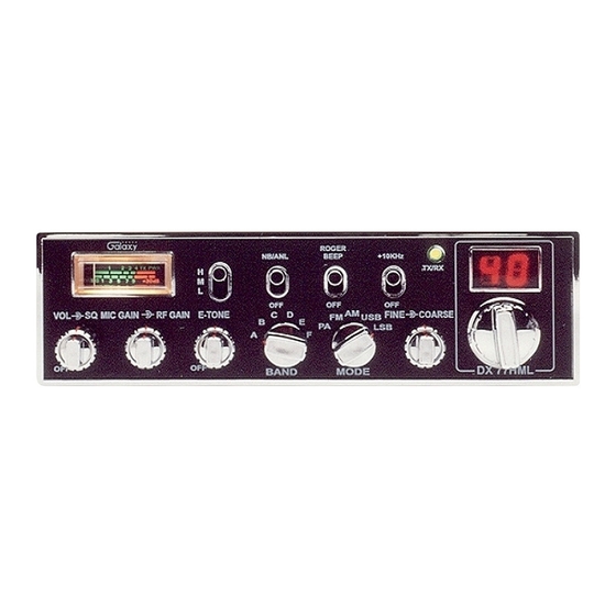
IGNITION NOISE INTERFERENCE Operation Use of a mobile receiver at low signal levels is normally limited by the presence of electrical noise. The primary source of noise in automobile installations is from the generator and ignition system in the vehicle. Under CONTROL FUNCTIONS most operating conditions, when signal level is adequate, the background There are fourteen controls and three indicators on the front panel of your... - Page 5 4. RF GAIN CONTROL (outer dual concentric): Use to reduce the gain 15. +10KHz FREQUENCY SHIFT SWITCH. When switch is pressed the of the RF amplifier under strong signal conditions. frequency is shifted 10KHz up on following channels. A channel can be used by setting this switch to +10KHz position.
-
Page 6: Rear Panel
REAR PANEL PRESS-TO-TALK MICROPHONE The receiver and transmitter are controlled by the press-to-talk switch on the microphone. Press the switch and the transmitter is activated, release switch to receive. When transmitting, hold the microphone two inches from the mouth and speak clearly in a normal “voice”. The radios come complete with low-impedance (500 ohm) dynamic microphone. -
Page 7: Receiving Ssb Signals
RECEIVING SSB SIGNALS Once the desired SSB mode has been selected, frequency adjustment may be necessary in order to make the incoming signal intelligible, the CLARIFIER control allows the operator to vary frequency above and below There are four types of signals presently used for communications: FM, the exact-center frequency of the received signal. -
Page 8: Alternate Microphones And Installation
ALTERNATE MICROPHONES AND INSTALLATION For best results, the user should select a low-impedance dynamic type microphone or a transistorized microphone. Transistorized type microphones have a low output impedance characteristic. The microphones must be provided with a four-lead cable. The audio conductor and its shielded lead comprise two of the leads. - Page 9 MEMO Fig. 5 Microphone plug pin numbers viewed from rear of pin receptacle. Be sure that the housing and the knurled ring of Fig. 4 are pushed back onto the microphone cable before starting to solder. If the washer is not captive to the pin receptacle body, make sure that it is placed on the threaded portion of the pin receptacle body before soldering.
- Page 10 MEMO MEMO - 17 - - 18 -...
Need help?
Do you have a question about the DX-77HML and is the answer not in the manual?
Questions and answers