Advertisement
DX 98VHP
B IG R IG
S E R IE S
D
E
T A L K B A C K
C
F
9
B
G
S
dB
A
H
O FF
PO
A M
SW R
SWR
U SB
LSB PW R
R B O FF
V O L
SQ
MIC
R F
D IM
D X 9 8 V HP
O FF
O FF
10 Meter
Amateur Mobile Transceiver
With Built-in Frequency Counter &
StarLite Face Plate
OWNER'S MANUAL
EC H O
+ 1 0 K H z
N B/A N L
F.D .
PA
O FF
V C O FF
O FF
PW R
EC H O
T IME
FIN E
C O A R SE
TABLE OF CONTENTS
CHAPTER 1
Specifications . . . . . . . . . . . . . . . . . . . . . . . . . . . . . . . . . . . . . . . . . . . . . .
CHAPTER 2
Installation . . . . . . . . . . . . . . . . . . . . . . . . . . . . . . . . . . . . . . . . . . . . . . . .
Installing The Radio . . . . . . . . . . . . . . . . . . . . . . . . . . . . . . . . . . . . . . . .
Ignition Noise Interference . . . . . . . . . . . . . . . . . . . . . . . . . . . . . . . . . . .
Antenna . . . . . . . . . . . . . . . . . . . . . . . . . . . . . . . . . . . . . . . . . . . . . . . . . .
External Speaker . . . . . . . . . . . . . . . . . . . . . . . . . . . . . . . . . . . . . . . . . . .
Public Address . . . . . . . . . . . . . . . . . . . . . . . . . . . . . . . . . . . . . . . . . . . .
CHAPTER 3
Operation . . . . . . . . . . . . . . . . . . . . . . . . . . . . . . . . . . . . . . . . . . . . . . . . .
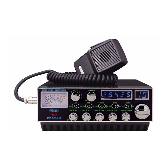
Front Panel . . . . . . . . . . . . . . . . . . . . . . . . . . . . . . . . . . . . . . . . . . . . . . .
Rear Panel . . . . . . . . . . . . . . . . . . . . . . . . . . . . . . . . . . . . . . . . . . . . . . . .
Procedure to Receive and Transmit . . . . . . . . . . . . . . . . . . . . . . . . . . . .
Receiving SSB Signals . . . . . . . . . . . . . . . . . . . . . . . . . . . . . . . . . . . . . .
Alternate Microphone and Installation . . . . . . . . . . . . . . . . . . . . . . . . . .
PAGE
1
2
3
3
4
4
4
4
5
5
8
9
10
12
Advertisement
Table of Contents

Related Manuals for Galaxy DX 98VHP


Summary of Contents for Galaxy DX 98VHP
- Page 1 TABLE OF CONTENTS PAGE CHAPTER 1 Specifications ..........DX 98VHP CHAPTER 2 Installation .
-
Page 2: Chapter 1 Specifications
CHAPTER 1 SPECIFICATIONS CHAPTER 2 INSTALLATION GENERAL INSTALLING THE RADIO Model DX 98VHP Choose a convenient location for operation that does not interfere with driver or Frequency Range 28.315 ~ 28.755 MHz passenger. This radio is supplied with a universal mounting bracket. When mounting the bracket and radio to your car, make sure it is mechanically strong. -
Page 3: Chapter 3 Operation
IGNITION NOISE INTERFERENCE CHAPTER 3 OPERATION With weak signals, you may experience interference of the signal by background noise. This radio has NB and ANL circuits that will help reduce background noise from CONTROL FUNCTIONS sources such as your ignition system. However, background electrical noise may come from several sources and all noise may not be eliminated. - Page 4 5. SQUELCH: This knob is used to eliminate background noise being heard through 17. PWR/SWR/RB SWITCH: When in the RB position, the radio transmits an audio the receiver, which can be disturbing when no transmissions are being heard tone at the end of your transmission to indicate that transmission has ended. As a through the receiver.
-
Page 5: Rear Panel
REAR PANEL PROCEDURE TO RECEIVE AND TRANSMIT A. MICROPHONE The push-to-talk switch on the microphone controls the receiver and transmitter. Press the switch and the transmitter will activate, release switch to receive. When transmitting, hold the microphone two inches from your mouth and speak clearly in a normal voice. This transceiver comes complete with a low impedance dynamic microphone. -
Page 6: Receiving Ssb Signals
Thus when a voice is used in place of a whistle or tone, in the proper listening mode RECEIVING SSB SIGNALS the voice will be received correctly whereas in the incorrect mode, the voice will be translated backwards and cannot be made intelligible by the COARSE/FINE control. There are four types of signals presently used for communications: FM, AM, USB When listening to an AM transmission, a correct side band is heard in either mode since and LSB. -
Page 7: Alternate Microphones And Installation
Before beginning the actual wiring, read carefully the circuit and wiring information ALTERNATE MICROPHONES AND INSTALLATION provided with the microphone you select. Use the minimum heat required in soldering the connections. Keep the exposed wire lengths to a minimum to avoid shorting when For best results, the user should select a low-impedance dynamic type microphone or the microphone plug is reassembled. - Page 8 5. The wires must now be soldered to the pins as indicated in the above wiring tables. 9. The two cable clamp retainer screws should now be tightened to secure the housing If a vise or clamping tool is available it should be used to hold the pin receptacle to the microphone cord.
- Page 9 MEMO MEMO...
-
Page 10: Warranty
We will repair and return your radio as soon as we can. We appreciate your choosing a Galaxy radio and we want you to be on the air as much as possible! Download this Manual Free of Charge at http://www.cbtricks.com/...
Need help?
Do you have a question about the DX 98VHP and is the answer not in the manual?
Questions and answers