Table of Contents
Advertisement
Quick Links
Advertisement
Table of Contents

Related Manuals for Galaxy DX-33HP


Summary of Contents for Galaxy DX-33HP
- Page 1 DX- 33HP POWER BAND RX/TX NB/ANL ECHO 9+30dB ECHO TIME BAND 10 Meter Amateur Mobile Transceiver Download this Manual Free of Charge at OWNER’S MANUAL http://www.cbtricks.com/ Printed In Malaysia AT1148010H...
- Page 2 TABLE OF CONTENTS Specifications Page GENERAL Specification ........Frequency Range 28.065 to 28.505 MHz Frequency Control...
- Page 3 RECEIVER Installation Sensitivity AM: 0.5 V for 10 dB (S+N)/N at greater than ½ -watt of audio output. FM: 1.0 V for 20 dB (S+N)/N at greater than LOCATION ½-watt of audio output. Plan the location of the transceiver and microphone bracket before starting the installation.
- Page 4 IGNITION NOISE INTERFERENCE Use of a mobile receiver at low signal levels is normally limited by the NOTE presence of electrical noise. The primary source of noise in automobile installations is from the generator and ignition system in the vehicle. Under most operating THE PROPER SETTING IS ACHIEVED WHEN THE SWR IS conditions, when signal level is adequate, the background noise does not present a 1.5 OR BELOW, AND WHEN IT HAS THE SAME READING...
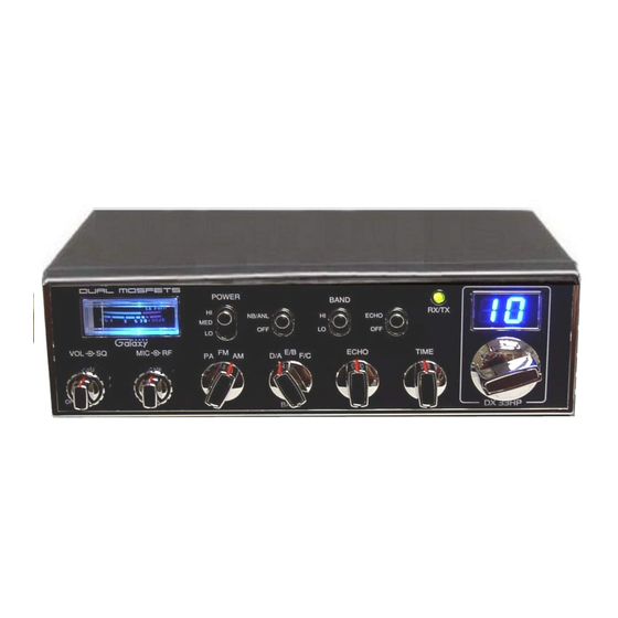
- Page 5 Operation EXTERNAL SPEAKER The external speaker jack (EXT.SPK) on the rear panel is used for remote CONTROL FUNCTIONS receiver monitoring. The external speaker should have 8 ohms impedance and be There are thirteen controls and three indicators on the front panel of your able to handle at least 4 watts.
- Page 6 RF GAIN CONTROL (outer dual concentric). Use to reduce the gain of the REAR PANEL receive under strong signal conditions. MODE (PA/FM/AM) SWITCH. This switch is used to select PA, FM, AM mode of operation. When you set to PA position, the transceiver acts as a public address amplifier.
- Page 7 PRESS-TO-TALK MICROPHONE ALTERNATE MICROPHONES AND INSTALLATION The receiver and transmitter are controlled by the press-to-talk switch on the For best results, the user should select a low-impedance dynamic type microphone. Press the switch and the transmitter is activated, release switch to microphone or a transistorized microphone.
- Page 8 Fig. 3 Microphone plug pin numbers viewed from rear of pin receptacle. Be sure that the housing and the knurled ring of Fig. 2 are pushed back onto the microphone cable before starting to solder. If the washer is not captive to the pin receptacle body, make sure that it is placed on the threaded portion of the pin receptacle body before soldering.
Need help?
Do you have a question about the DX-33HP and is the answer not in the manual?
Questions and answers
on a galaxy 33 hp what does the band selector (A,B, C..ect)need to be on for channel 19