Advertisement
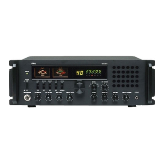
DX 2517
SWR
RX / TX
9
WATTS
SIGNAL
POWER
CHANNEL
ON
SWR
NB / ANL
R.BEEP
+10KHz
NF
OFF
CAL
OFF
OFF
NORMAL
OFF
CALIBRATE
T.B.
DIM
MIC
RF
TIME
ECHO
OFF
OFF
·
·
AM
FM
SSB
Amateur Base Station Transceiver
OWNER'S MANUAL
2517
PA
FM
AM
USB
LSB
CW
MODE
RF POWER
AM
USB
FM
LSB
PA
CW
BAND
SQUELCH
VOLUME
FINE
COARSE PHONE
C
D
B
E
A
F
·
·
CW
PA
Advertisement
Table of Contents

Related Manuals for Galaxy DX 2517


Summary of Contents for Galaxy DX 2517
- Page 1 DX 2517 2517 RX / TX WATTS SIGNAL POWER CHANNEL NB / ANL R.BEEP +10KHz MODE RF POWER NORMAL MICROPHONE CALIBRATE T.B. TIME ECHO BAND SQUELCH VOLUME FINE COARSE PHONE · · · · Amateur Base Station Transceiver OWNER’S MANUAL...
- Page 2 TABLE OF CONTENTS SPECIFICATION : GENERAL SPECIFICATIONS ............. Frequency Range 28.765 – 29.205 MHz Emission Types CW, FM, AM, USB, LSB INSTALLATION ..............Frequency Control Phase-Lock-Loop Synthesizer Frequency Tolerance 0.005% OPERATION Frequency Stability 0.003% Temperature Range C to +55 Introduction ..............Antenna Impedance 50 Ohms Antenna Connectors...
- Page 3 INSTALLATION: Antennas Location/Connection Antennas are purchased separately and include installation The transceiver should be placed in a convenient operating location instructions. Numerous type of antennas are available that range from close to an AC power outlet and the antenna lead in cable(s). emphasis on easy of installation to emphasis on performance.
-
Page 4: Public Address
OPERATION: Public address An external 8 ohms, 3 Watt speaker must be connected to the PA jack located on the rear panel when the transceiver is used as a public address system. The speaker should be directed away from the microphone to prevent acoustic feedback. - Page 5 position. This will give you an SWR reading. When you are 9. CHHANEL DISPLAY: The channel display indicates the finished, be sure to turn the “CALIBRATE” pot fully CCW to the current selected channel. “RF” position so you are able to read your output power. You will hear the “RF”...
- Page 6 18. CHANNEL SELECTOR: This control is used to select a 26. MODE LED INDICATORS: The lighted LED indicates which desired frequency. mode the radio is in. 19. MODE CONTROL: This control allows you to select one of 27. RX/TX LED: Lights green during receive and changes to red six operating modes: PA/FM/AM/USB/ LSB/CW during transmit.
- Page 7 6. REC JACK: The RCA-type (pin) jack provides audio output for B. PROCEDURE TO TRANSMIT connection to a tape recorder. This can be used to record 1. Set the MIC gain fully clockwise. incoming signals or your voice when transmitting. 2.
- Page 8 1. Set the unit in the receive mode as instructed under the operating procedure to receive section. 2. Set the mode switch to AM position, the SWR-CAL switch to the CAL position. 3. Press the push-to-talk switch on the microphone and turn the calibrate control clockwise (past click) so that the SWR meter pointer exactly coincides with the set mark on the scale.
- Page 9 PRINTED IN TAIWAN AT0SSB010W - 15 -...
Need help?
Do you have a question about the DX 2517 and is the answer not in the manual?
Questions and answers