Table of Contents
Advertisement
Quick Links
Advertisement
Table of Contents

Related Manuals for Galaxy DX-55HP


Summary of Contents for Galaxy DX-55HP
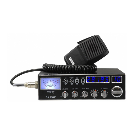
- Page 1 DX-55HP F.DISPLAY R.B. +10KHz SIGNAL POWER CLARIFIER DX 55HP BAND 10-Meter AM/FM Mobile Transceiver Built in Frequency Counter with Roger Beep OWNER’S MANUAL Printed In Malaysia A412308BTA...
-
Page 2: Table Of Contents
TABLE OF CONTENTS Specifications Page GENERAL Specification ........Channels 40 CH Frequency Range... -
Page 3: Installation
RECEIVER Installation Sensitivity AM: 1.0 V for 10 dB (S+N)/N at greater than ½ -watt of audio output. LOCATION FM: 1.0 V for 20 dB (S+N)/N at greater Plan the location of the transceiver and microphone bracket before than ½-watt of audio output. starting the installation. -
Page 4: Ignition Noise Interference
IGNITION NOISE INTERFERENCE TUNNING THE ANTENNA FOR OPTIMUM SWR Use of a mobile receiver at low signal levels is normally limited by the Since there is such a wide variety of base and mobile antennas, this presence of electrical noise. The primary source of noise in automobile section will strictly concern itself to the various types of mobile adjustable installations is from the generator and ignition system in the vehicle. -
Page 5: External Speaker
C. Check your coaxial cable routing (it may be pinched when routed Operation into the car). D. Try a different location on your car (keeping in mind the radiation pattern you wish) CONTROL FUNCTIONS There are thirteen controls and three indicators on the front panel of Is the antenna perfectly vertical? your transceiver. - Page 6 5. DIMMER (inner dual concentric). Turns on/off the frequency display, channel number and the meter lamp. Switch on at minimum brightness and rotate clockwise for brighter illumination. Normal +10KHz 6. RF POWER (outer dual concentric). This switch is used to select transmitting power.
-
Page 7: Rear Panel
REAR PANEL PRESS-TO-TALK MICROPHONE The receiver and transmitter are controlled by the press-to-talk switch on the microphone. Press the switch and the transmitter is activated, release switch to receive. When transmitting, hold the microphone two inches from the mouth and speak clearly in a normal “voice”. The radios come complete with low-impedance (500 ohm) dynamic microphone. -
Page 8: Alternate Microphones And Installation
ALTERNATE MICROPHONES AND INSTALLATION For best results, the user should select a low-impedance dynamic type microphone or a transistorized microphone. Transistorized type microphones have a low output impedance characteristic. The microphones must be provided with a four-lead cable. The audio conductor and its shielded lead comprise two of the leads. - Page 9 MEMO Fig. 3 Microphone plug pin numbers viewed from rear of pin receptacle. Be sure that the housing and the knurled ring of Fig. 2 are pushed back onto the microphone cable before starting to solder. If the washer is not captive to the pin receptacle body, make sure that it is placed on the threaded portion of the pin receptacle body before soldering.
- Page 10 We will repair and return your radio as soon as we can. We appreciate your choosing a Galaxy radio and we want you to be on the air as much as possible! Be sure to visit our web site at www.GalaxyRadios.com...
Need help?
Do you have a question about the DX-55HP and is the answer not in the manual?
Questions and answers