Table of Contents
Advertisement
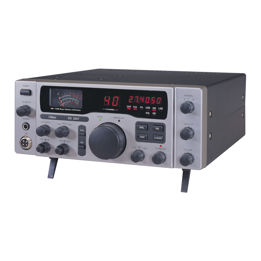
DX 2547
CHAPTER 1
1.0
General . . . . . . . . . . . . . . . . . . . . . . . . . . . . . . . . . . . . . . . . . . . . . . . . . 2
1.1
Transmitter . . . . . . . . . . . . . . . . . . . . . . . . . . . . . . . . . . . . . . . . . . . . . . . 2
1.2
Receiver . . . . . . . . . . . . . . . . . . . . . . . . . . . . . . . . . . . . . . . . . . . . . . . . .
CHAPTER 2
2.0
Introduction . . . . . . . . . . . . . . . . . . . . . . . . . . . . . . . . . . . . . . . . . . . . . .
2.1
Control And Connections . . . . . . . . . . . . . . . . . . . . . . . . . . . . . . . . . . . . 3
2.1.1
Front Panel . . . . . . . . . . . . . . . . . . . . . . . . . . . . . . . . . . . . . . . . . . . . . . . 3
2.1.2
Rear Panel . . . . . . . . . . . . . . . . . . . . . . . . . . . . . . . . . . . . . . . . . . . . . . .
2.1.3
Frequency Chart . . . . . . . . . . . . . . . . . . . . . . . . . . . . . . . . . . . . . . . . . . 8
2.2
Microphone . . . . . . . . . . . . . . . . . . . . . . . . . . . . . . . . . . . . . . . . . . . . . .
2.3
Operation . . . . . . . . . . . . . . . . . . . . . . . . . . . . . . . . . . . . . . . . . . . . . . . .
2.3.1
Procedure To Receive . . . . . . . . . . . . . . . . . . . . . . . . . . . . . . . . . . . . . . .
2.3.2
Procedure To Transmit . . . . . . . . . . . . . . . . . . . . . . . . . . . . . . . . . . . . . . 9
2.4
Alternate Microphones And Installation . . . . . . . . . . . . . . . . . . . . . . . . . 10
3.0
Introduction . . . . . . . . . . . . . . . . . . . . . . . . . . . . . . . . . . . . . . . . . . . . . .
3.1
Pll Circuit . . . . . . . . . . . . . . . . . . . . . . . . . . . . . . . . . . . . . . . . . . . . . . 11
3.2
Receiver Circuit . . . . . . . . . . . . . . . . . . . . . . . . . . . . . . . . . . . . . . . . . . .
3.3
Transmitter Modulation Circuit . . . . . . . . . . . . . . . . . . . . . . . . . . . . . . .
3.4
Transmitter Amplifier Circuit . . . . . . . . . . . . . . . . . . . . . . . . . . . . . . . . 11
CHAPTER 4
ALIGNMENT
4.0
Required Test Equipment . . . . . . . . . . . . . . . . . . . . . . . . . . . . . . . . . . . 14
4.1
Alignment Procedures . . . . . . . . . . . . . . . . . . . . . . . . . . . . . . . . . . . . . . 14
4.1.1
Pll Alignment . . . . . . . . . . . . . . . . . . . . . . . . . . . . . . . . . . . . . . . . . . . 14
4.1.2
Transmitter Alignment . . . . . . . . . . . . . . . . . . . . . . . . . . . . . . . . . . . . . 15
4.1.3
Receiver Alignment . . . . . . . . . . . . . . . . . . . . . . . . . . . . . . . . . . . . . . . .
CHAPTER 5
5.0
Precautions . . . . . . . . . . . . . . . . . . . . . . . . . . . . . . . . . . . . . . . . . . . . . . 18
5.1
Periodic Inspection . . . . . . . . . . . . . . . . . . . . . . . . . . . . . . . . . . . . . . . . 18
5.2
Fuse Replacement . . . . . . . . . . . . . . . . . . . . . . . . . . . . . . . . . . . . . . . . . 18
CHAPTER 6
DIAGRAMS AND PART LIST
6.0
PCB Layout and Part List . . . . . . . . . . . . . . . . . . . . . . . . . . . . . . . . . . . 19
- 1 -
TABLE OF
CONTENTS
PAGE
2
3
7
9
9
9
11
11
11
16
CHAPTER 1
Advertisement
Table of Contents

Related Manuals for Galaxy DX 2547


Summary of Contents for Galaxy DX 2547
-
Page 1: Specifications
TABLE OF DX 2547 CONTENTS PAGE CHAPTER 1 SPECIFICATIONS General ..........2 Transmitter . -
Page 2: General
DX 2547 SPECIFICATIONS 1.0 GENERAL Model DX 2547 Frequency Range 26.965 – 27.405 MHz Emission Modes AM/USB/LSB Frequency Control Phase Lock Loop (PLL) synthesizer Frequency Tolerance 0.005 % Frequency Stability 0.001 % Operating Temperature Range -30°C to +50°C Microphone Dynamic PTT, 500 Ω... -
Page 3: Introduction
VOLUME Figure 2-1 Front Panel 2.0 INTRODUCTION This section explains the basic operating procedures for the Galaxy DX 2547 Base Station transceiver. 2.1 CONTROL AND CONNECTIONS 2.1.1 FRONT PANEL Refer to the above Figure 2-1 for the location of the following controls: 1. - Page 4 This control allows you to select one of the following operating modes: USB, AM or LSB. 14. GNF SWITCH When this switch is pressed in, the radio is in CB operation but the Galaxy Noise Filter is engaged. This is a special noise filter that de-emphasizes audio high frequency response in order to increase the signal-to-noise ratio of weak signals.
- Page 5 When activated, allows adjustment of the receive frequency above or below the channel frequency by up to 800Hz. Although this control is intended primarily to tune in SSB signals, it may be used to optimize AM signals as well. 17. CLARIFIER LED This LED lights when the Clarifier control is activated.
- Page 6 31. ANL LED This LED lights red when the ANL is on. 32. USB LED This LED lights red when the radio is in the USB mode. 33. AM LED This LED lights red when the radio is in the AM mode. 34.
-
Page 7: Rear Panel
Figure 2-2 Rear Panel 1. AC POWER CORD Connect to AC power outlet for AC main supply. 2. FUSE Accommodates a fuse for AC input circuit protection. Use a 125V 2A fuse for replacement. 3. DC POWER This accepts a 13.8V DC power cable with built-in 7A fuse. The power cord provided with the radio has a black and red wire. - Page 8 CHANNEL CHANNEL FREQUENCY CHANNEL CHANNEL FREQUENCY (MHz) (MHz) 26.965 27.215 26.975 27.225 26.985 27.255 27.005 27.235 27.015 27.245 27.025 27.265 27.035 27.275 27.055 27.285 27.065 27.295 27.075 27.305 27.085 27.315 27.105 27.325 27.115 27.335 27.125 27.345 27.135 27.355 27.155 27.365 27.165 27.375 27.175...
-
Page 9: Microphone
microphone two inches from your mouth and speak clearly in a normal voice. The radio comes complete with a low impedance (500 ohm) dynamic microphone. 2.3 OPERATION 2.3.1 PROCEDURE TO RECEIVE 1. Be sure that the power source, microphone and antenna are connected to the proper connectors before going to the next step. -
Page 10: Chapter 3
Pin Number Mic Cable Lead Audio Shield Audio Lead Transmit Control Receive Control Figure 2-3 Your Transceiver Microphone Schematic Figure 2-4 Microphone plug an pin numbers viewed from rear of pin receptacle. CHAPTER 3 CIRCUIT DX 2547 DESCRIPTION - 10 -... - Page 11 3.0 INTRODUCTION This section explains the technical theory of operation for the Galaxy DX 2547 Base Station transceiver. 3.1 PLL CIRCUIT The Phase Lock Loop (PLL) circuit is responsible for developing the receiver’s first local oscillator signal and the transmitter’s exciter signal. The PLL circuit consists primarily of IC2, IC3, Q25, Q29 and Q28.
- Page 12 - 12 -...
- Page 13 - 13 -...
-
Page 14: Required Test Equipment
CHAPTER 4 DX 2547 ALIGNMENT 4.0 REQUIRED TEST EQUIPMENT DC Power Supply (13.8VDC, 10A) Frequency Counter (100 MHz) RF Wattmeter (100 MHz, 50W) RF Signal Generator (100 MHz) Multimeter (Digital) Automatic Distortion Meter Automatic Modulation Meter Oscilloscope (50 MHz) Audio Signal Generator Sinad Meter 4.1 ALIGNMENT PROCEDURES... -
Page 15: Receiver Alignment
ITEM U.U.T. SETTING ADJUST MEASUREMENT POINT BIAS Current Set radio to CH 19 USB TX mode. Modulation Off. Connect current meter to TP7(+) and TP9 (-) VR12 50 mA Connect current meter to TP7 (+) and TP8 (-) VR10 100 mA SSB APC Set radio to CH 19 USB RX mode. - Page 16 ITEM U.U.T. SETTING ADJUST MEASUREMENT POINT AM Sensitivity Set radio to CH 19 AM RX mode. Set RF GAIN Fully Clockwise. L2,L3,L5,L6, Audio Output > 2V Set SQ Fully Counter Clockwise. L7,L8,L9,L10 S/N > 10 dB. Set VOL Control at 2 o’clock. Set NB/ANL switch to OFF position.
- Page 17 Figure 4-1 Transmitter test setup Figure 4-2 Receiver test setup - 17 -...
-
Page 18: Precautions
CHAPTER 5 DX 2547 MAINTENANCE 5.0 PRECAUTIONS The inherent quality of the solid-state components used in this transceiver will provide many years of continuous use. Taking the following precautions will prevent damage to the transceiver. (i) Never key the transmitter unless an antenna or suitable dummy load is connected to the antenna receptacle. -
Page 19: Parts List
DIAGRAMS & DX 2547 PARTS LIST 6.0 GENERAL Information on most electrical and mechanical parts is included in the parts list. The reference designators are in alphanumeric order. - 19 -... - Page 20 - 20 -...
- Page 21 PART LIST: DX 2547 ROTARY SW P.C.B ITEM REFERENCE NUMBER RANGER PART DESCRIPTION NUMBER EPT0SSB30A ROTARY SW PCB C/F/R 470 Ω 0.1W R301 RCY014714Z C/F/R 1K Ω 0.1W R302,R303,R304,R305, RCY011024Z R306,R308,R309,R310, R311,R312,R313 C/F/R 3.3K Ω 0.1W R314 RCY013324Z C/F/R 10K Ω 0.1W...
- Page 22 PART LIST: DX 2547 HP ANT P.C.B ITEM REFERENCE NUMBER RANGER PART DESCRIPTION NUMBER EPT360042Z ANT P.C.B RCY010004Z 0 OHM 0.1W RCY014714Z 470 OHM 0.1W R3,R4 RCY011014Z 100 OHM 0.1W RCY013314Z 330 OHM 0.1W R5,R11 RCY011024Z 1K OHM 0.1W RCY012224Z 2.2K OHM 0.1W...
- Page 23 PART LIST: - 23 -...
- Page 24 DX 2547 HP ANT P.C.B ITEM REFERENCE NUMBER RANGER PART DESCRIPTION NUMBER EPT009830Z ANT PCB C/F/R 10 Ω 0.1W R312 RCY011004Z C/F/R 100 Ω 0.1W R308 RCY011014Z C/F/R 270 Ω 0.1W R316 RCY012714Z C/F/R 2.2K Ω 0.1W R323 RCY012224Z C/F/R 4.7K Ω 0.1W...
- Page 25 PART LIST: DX 2547 PUSH SW P.C.B ITEM REFERENCE NUMBER RANGER PART DESCRIPTION NUMBER EPT254720Z PUSH SW PCB PA,RB EWPS33033X PUSH SW J201 EX07N49140 PCB CONN/S 2PIN CB/G/PA EX07N49144 PCB CONN/S 3PIN REMARK: COPPER SIDE (WHITE) - 25 -...
- Page 26 PART LIST: DX 2547 PUSH SW P.C.B ITEM REFERENCE NUMBER RANGER PART DESCRIPTION NUMBER EPT254750Z PUSH SW PCB J501 EX07N48234 PCB CONN/S 2PIN J503 EX07N48761 PCB CONN/S 4PIN J502 EX07N48667 PCB CONN/S 5PIN 9/NOL/19 EWRT32087S ROTARY SW SQUELCH RV50303532 VR 50KB...
- Page 27 - 27 -...
- Page 28 PART LIST: DX 2547 DISPLAY P.C.B ITEM REFERENCE NUMBER RANGER PART DESCRIPTION NUMBER EPT254740Z DISPLAY PCB C401 CEM164767Z E/C 47uF 16WV C/F/R 0 Ω 1/16W R414,R420,R421 RCP160004Z C/F/R 100 Ω 1/16W R422 RCP161014Z C/F/R 470 Ω 1/16W R401-R408 RCP164714Z C/F/R 1K Ω 1/16W...
- Page 29 PART LIST: DX 2547 TALKBACK P.C.B ITEM REFERENCE NUMBER RANGER PART DESCRIPTION NUMBER EPT254760Z TALKBACK PCB TALKBACK PCB EX07N48667 PCB CONN/S 5PIN TALKBACK RV20303558 VR 20 LA REMARK: COPPER SIDE (WHITE) - 29 -...
- Page 30 PART LIST: DX 2547 MIC P.C.B ITEM REFERENCE NUMBER RANGER PART DESCRIPTION NUMBER EPT253750Z MIC PCB C503,C504,C505,C506 CC0501027L C/C 0.001uF 50WV C501,C502 CC0501037L C/C 0.01uF 50WV Q501 TDTA0124ES TR DTA124ES L501 ECCHK16001 CHOKE COIL L502 ECBAD18506 BEAD COIL EX06N41101 MIC JACK...
- Page 31 - 31 -...
- Page 32 PART LIST: DX 2547 COUNTER P.C.B ITEM REFERENCE NUMBER RANGER PART DESCRIPTION NUMBER EPT900040Z COUNTER P.C.B RCY010004Z 0 OHM 0.1W R19-R39 RCY011014Z 100 OHM 0.1W RCY013314Z 330 OHM 0.1W RCY014714Z 470 OHM 0.1W R4,R5 RCY012224Z 2.2K OHM 0.1W RCY014724Z 4.7K OHM 0.1W...
- Page 33 PART LIST: DX 2547 DIM / RF / MIC GAIN P.C.B ITEM REFERENCE NUMBER RANGER PART DESCRIPTION NUMBER EPT254770Z DIM/RF/MIC GAIN PCB J601 EX07N49095 PCB CONN/S 6PIN J603 EX07N48947 PCB CONN/S 3PIN J602 EX07N48234 PCB CONN/S 2PIN RF/MIC GAIN RV10203524...
- Page 34 PART LIST: DX 2547 RF / MOD P.C.B ITEM REFERENCE NUMBER RANGER PART DESCRIPTION NUMBER EPT254780Z RF / MOD P.C.B J801 EX07N48234 PCB CONN/S 2PIN J802 EX07N48620 PCB CONN/S 7PIN SWR/MOD/PWR EWRT32087S ROTARY SW RF POWER RV50203525 VR 5KB REMARK:...
- Page 35 PART LIST: DX 2547 MODE / FINE P.C.B ITEM REFERENCE NUMBER RANGER PART DESCRIPTION NUMBER EPT254790Z MODE / FINE PCB J903 EX07NM48947 PCB CONN/S 3PIN J901,J902 EX07N48761 PCB CONN/S 4PIN USB/ AM/ LSB EWRT32087S ROTARY SW CLARIFIER RV10203528 VR IKB...
- Page 36 PART LIST: DX 2547 EAR P.C.B ITEM REFERENCE NUMBER RANGER PART DESCRIPTION NUMBER EPT253790Z EAR PCB PA,EXT SP EX06N41034 EAR JACK J2,J3 EX07N48223 PCB CONN/S 2PIN EX07N48350 PCB CONN/S 3PIN WX01070710 JUMPER WIRE C902,C901 CC0501027L C/C 0.001uF 50WV REMARK: COPPER SIDE (WHITE)
- Page 37 PART LIST: DX 2547 DC P.C.B ITEM REFERENCE NUMBER RANGER PART DESCRIPTION NUMBER EPT253770Z DC PCB C/F/R 10K Ω 1/4W R707 RCU141034Z C/F/R 47 Ω 1W R704 RCP104704Z C/F/R 100 Ω 1W R705 RCP101014Z C/F/R 220 Ω 1W R706 RCP102214Z C/F/R Ω...
- Page 38 PART LIST: DX 2547 DC P.C.B ITEM REFERENCE NUMBER RANGER PART DESCRIPTION NUMBER EPT253780Z DC PCB DC PCB TZ2N05301Z TR 2N5301 REMARK: COPPER SIDE (WHITE) - 38 -...
- Page 39 DX 2547 MAIN PCB - 39 -...
- Page 40 1/16W PART LIST RCP163934Z 39K Ω DX 2547 MAIN PCB 1/16W R7,29,61,63,96,126, RCP164734Z 47K Ω 150,157,185,218,222, 1/16W REFERENCE RANGER DESCRIPTION NUMBER PART NO. R21,105,107 RCP166834Z 68K Ω EPT069610Z MAIN PCB 1/16W R246 RCP161004Z 10 Ω 1/16W RCP168234Z 82K Ω R267 RCP161504Z 15 Ω...
- Page 41 188,189,205,305,219, EDZD05759Z ZENER DIODE 229,230,232,241,247, EDZD05519Z ZENER DIODE 254,255,265,267,269, EDSV00251Z DIODE 271,278,284,285,298 SVC-251SPA C32,42,45,46,162,163 CC0504727L 0.0047UF L2,3 ECIFT12002 I.F.T ,221,64 50WV L20,21,22 ECIFT12012 I.F.T C155 CC0502237L 0.022UF ECIFT12013 I.F.T 50WV L23,24 ECIFT12016 I.F.T C200 CC1001037L 0.01UF L1,11 ECIFT12252 I.F.T 100WV ECIFT12255 I.F.T C199...
- Page 42 SET SCREW E/C,FRONT PANEL JS013008TH SCREW FRONT PANEL,MAIN PCB JS033006MN SET SCREW AV/DC,SWITCH JS052004MN SET SCREW JS052012MN SET SCREW DX 2547 MISC. PARTS TOP,BOTTOM, JS053006MN SET SCREW HEAT SINK, SET CHASSIS REFERENCE RANGER DESCRIPTION ANT JACK JS053006TN SET SCREW NUMBER PART NO.
- Page 43 Main PCB Adjustment Location - 43 -...
- Page 44 UPDATES & CORRECTIONS Any updates or corrections to this Service Manual will be included in the Tech Support section of our website at www.GalaxyRadios.com. - 44 -...
Need help?
Do you have a question about the DX 2547 and is the answer not in the manual?
Questions and answers