Table of Contents
Advertisement
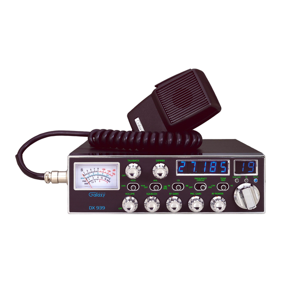
DX-939
Solid State Citizens Band
AM Mobile Transceiver
With Blue Illuminated Lite
OWNERS MANUAL
TABLE OF CONTENTS
CHAPTER 1
CHAPTER 2
Installation
Location . . . . . . . . . . . . . . . . . . . . . . . . . . . . . . . . . . . . . . . . . . . . . . . . . . .
Mounting The Radio . . . . . . . . . . . . . . . . . . . . . . . . . . . . . . . . . . . . . . . . . .
Ignition Noise Interference . . . . . . . . . . . . . . . . . . . . . . . . . . . . . . . . . . . . .
Antenna . . . . . . . . . . . . . . . . . . . . . . . . . . . . . . . . . . . . . . . . . . . . . . . . . . . .
Tuning The Antenna For Optimum SWR . . . . . . . . . . . . . . . . . . . . . . . . . .
External Speaker . . . . . . . . . . . . . . . . . . . . . . . . . . . . . . . . . . . . . . . . . . . . .
Public Address . . . . . . . . . . . . . . . . . . . . . . . . . . . . . . . . . . . . . . . . . . . . . . .
CHAPTER 3
Operation
Control Functions . . . . . . . . . . . . . . . . . . . . . . . . . . . . . . . . . . . . . . . . . . . .
Front Panel . . . . . . . . . . . . . . . . . . . . . . . . . . . . . . . . . . . . . . . . . . . . . . . . .
Rear Panel . . . . . . . . . . . . . . . . . . . . . . . . . . . . . . . . . . . . . . . . . . . . . . . . . .
Frequency Chart . . . . . . . . . . . . . . . . . . . . . . . . . . . . . . . . . . . . . . . . . . . . .
Procedure to Receive and Transmit . . . . . . . . . . . . . . . . . . . . . . . . . . . . . .
Receiving SSB Signals . . . . . . . . . . . . . . . . . . . . . . . . . . . . . . . . . . . . . . . .
Maintenance And Adjustment . . . . . . . . . . . . . . . . . . . . . . . . . . . . . . . . . .
A Few Rules That Should Be Obeyed . . . . . . . . . . . . . . . . . . . . . . . . . . . .
How Your CB Can Serve You . . . . . . . . . . . . . . . . . . . . . . . . . . . . . . . . . .
Use Channel 9 For Emergency Message Only . . . . . . . . . . . . . . . . . . . . . .
- 1 -
PAGE
2
3
3
4
4
5
6
6
7
7
10
11
12
13
15
18
19
19
20
Advertisement
Table of Contents

Related Manuals for Galaxy DX-939


Summary of Contents for Galaxy DX-939
-
Page 1: Table Of Contents
TABLE OF CONTENTS PAGE CHAPTER 1 Specifications ..........DX-939 CHAPTER 2 Installation... -
Page 2: Chapter 1 Specifications
CHAPTER 1 SPECIFICATIONS CHAPTER 2 INSTALLATION GENERAL LOCATION Plan the location of the transceiver and microphone bracket before starting the Model DX-939 installation. Select a location that is convenient for operation and does not interfere Channels with the driver or passengers. In automobiles, the transceiver is usually mounted Frequency Range 26.965 ~ 27.405 MHz the dash panel with the microphone bracket beside it. -
Page 3: Ignition Noise Interference
IGNITION NOISE INTERFERENCE TUNING THE ANTENNA FOR OPTIMUM S.W.R Use of a mobile receiver at low signal levels is normally limited by the presence Since there is such a wide variety of base and mobile antennas, this section will of electrical noise. The primary source of noise in automobile installation is from strictly concern itself to the various types of mobile adjustable antennas. -
Page 4: External Speaker
If you’re having difficulties in adjusting your antenna, check the following: CHAPTER 3 OPERATION All doors must be closed when adjusting the antenna b. Make sure the antenna base is grounded. Check your coaxial cable routing (it may be pinched when routed into the car) CONTROL FUNCTIONS d. - Page 5 5. DIMMER CONTROL : This knob controls the level of brightness for the 14. Display ON/OFF SWITCH : When the switch is in the F.D.OFF position, the meter lamp and the channel display. Also, pushing this knob turns the meter frequency Display is OFF.
- Page 6 REAR PANEL CONNECTOR FREQUENCY CHART Channel Channel Frequency Channel Channel Frequency 26.965 MHz 27.215 MHz 26.975 MHz 27.225 MHz 26.985 MHz 27.255 MHz 27.005 MHz 27.235 MHz 27.015 MHz 27.245 MHz 27.025 MHz 27.265 MHz 27.035 MHz 27.275 MHz 27.055 MHz 27.285 MHz 1.
-
Page 7: Procedure To Receive And Transmit
PROCEDURE TO RECEIVE AND TRANSMIT ALTERNATE MICROPHONES AND INSTALLATION A. MICROPHONE For best results, the user should select a low-impedance dynamic type microphone or a transistorized microphone. Transistorized type microphones have The receiver and transmitter are controlled by the push-to-talk switch on the low output impedance characteristics. - Page 8 Before beginning the actual wiring, read carefully the circuit and wiring microphone jack on the front panel. The numbers of the microphone plug are information provided with the microphone you select. Use the minimum heat shown in Fig. 3, as viewed from the back of the plug. Before soldering the wire required in soldering the connections.
-
Page 9: Maintenance And Adjustment
MAINTENANCE AND ADJUSTMENT A FEW RULES THAT SHOULD BE OBEYED This transceiver is specifically designed for the environment encountered in 1. You are not allowed to carry on a conversation with another station for more mobile installations. The use of all solid state circuitry and its light weight result in than five minutes at a time without taking a one-minute break, to give others a high reliability. - Page 10 USE CH 9 FOR EMERGENCY MESSAGES ONLY MEMO The FCC gives the following examples of permitted and prohibited types of communications for use in an emergency. These are guidelines and are not intended to be all inclusive. Permitted Example Message “A tornado sighted six miles north of town.
- Page 11 Two Year Warranty This new Galaxy radio is covered by a two year limited warranty. Here are the details. • All of our Galaxy radio model numbers begin with the letters “DX” and are covered by our Limited Two Year Parts and Labor Warranty.
Need help?
Do you have a question about the DX-939 and is the answer not in the manual?
Questions and answers