Table of Contents
Advertisement
Printed In Malaysia
AT2547010A
PD0009028
DX 2547
POWER
S
dB
MOD
TALKBACK
PWR
SWR
AM / SSB Base Station CB Radio
RX / TX
DX 2547
OFF
PHONES
RF POWER
MOD
SWR
PWR
R. B.
MIC
MIC
RF
DIM
TONE
PA
OFF
AM/ SSB Two Way
Citizen Band Base Station Transceiver
OWNER'S MANUAL
NORMAL
9
19
GNF
R.B.
PA
USB
AM
LSB
CHANNEL
ANL
NB
SWR ALERT
SQUELCH
ANL
NB
GNF
CLARIFIER
AM
CLARIFIER
VOLUME
USB
LSB
Advertisement
Table of Contents

Related Manuals for Galaxy DX 2547


Summary of Contents for Galaxy DX 2547
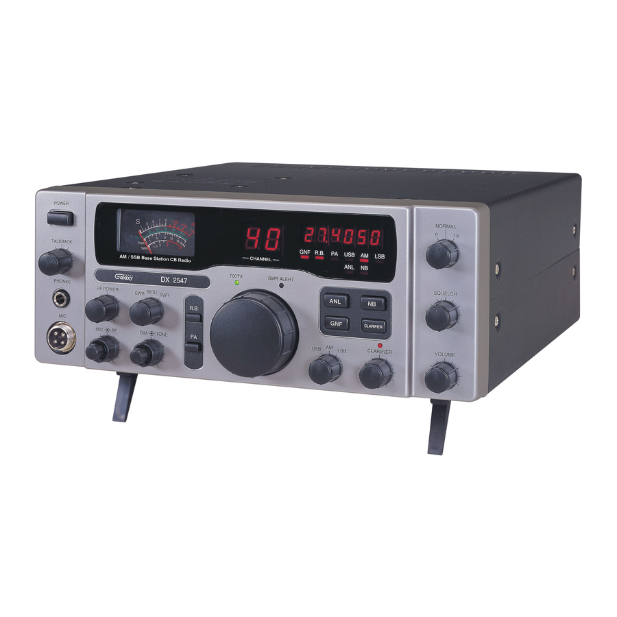
- Page 1 DX 2547 POWER NORMAL R.B. TALKBACK CHANNEL AM / SSB Base Station CB Radio RX / TX SWR ALERT SQUELCH DX 2547 PHONES RF POWER R. B. CLARIFIER TONE CLARIFIER VOLUME AM/ SSB Two Way Citizen Band Base Station Transceiver OWNER’S MANUAL Printed In Malaysia AT2547010A...
-
Page 2: Table Of Contents
TABLE OF CONTENTS CHAPTER 1 SPECIFICATIONS PAGE GENERAL CHAPTER 1 Channels Specifications ......... Frequency Range 26.965 ~ 27.405 MHz Emission... -
Page 3: Chapter 2 Installation
1. Vertical Ground Plane Antenna : Omni directional antennas provide CHAPTER 2 INSTALLATION optimum performance for contacting other fixed stations using vertical type antennas in addition to all mobile stations. For medium long range LOCATION communications work. Choose a location close to an AC power outlet and convenient for running the antenna lead-in cable. -
Page 4: External Speaker
EXTERNAL SPEAKER CHAPTER 3 OPERATION The external speaker jack (EXT. SP.) on the rear panel is used for remote receiver monitoring. The external speaker should have 8 ohms impedance CONTROL FUNCTIONS and be able to handle at least 4 watts. When the external speaker is plugged in, the internal speaker is disconnected. - Page 5 24. TX/RX LED : The red LED indicates the unit is in the transmit mode. the Galaxy Noise Filter is engaged. This is a special noise filter that de- The green LED indicates the unit is in the receive mode.
-
Page 6: Rear Panel
27. GNF LED : This LED lights red when the GNF is on. REAR PANEL 28. R.B. LED : This LED lights green when the Roger Beep is on. 29. FREQUENCY COUNTER : This display indicates the frequency of the selected channel. -
Page 7: Frequency Chart
FREQUENCY CHART PROCEDURE TO RECEIVE AND TRANSMIT Channel Channel Frequency Channel Channel Frequency A. MICROPHONE 26.965 MHz 27.215 MHz The receiver and transmitter are controlled by the push-to-talk switch on the microphone. Press the switch and the transmitter is activated, release switch 26.975 MHz 27.225 MHz to receive. -
Page 8: Receiving Ssb Signals
Thus when a voice is used in place of a whistle or tone, in the proper RECEIVING SSB SIGNALS listening mode the voice will be received correctly whereas in the incorrect mode, the voice will be translated backwards and cannot be made intelligible There are three types of signals presently used for communications in the by the CLARIFIER control. -
Page 9: Alternate Microphone And Installation
Before beginning the actual wiring, read carefully the circuit and wiring ALTERNATE MICROPHONES AND INSTALLATION information provided with the microphone you select. Use the minimum heat required in soldering the connections. Keep the exposed wire lengths to a For best results, the user should select a low-impedance dynamic type minimum to avoid shorting when the microphone plug is reassembled. -
Page 10: Maintenance And Adjustment
5. The wires must now be soldered to the pins as indicated in the above 9. The two cable clamp retainer screws should now be tightened to secure the wiring tables. If a vise or clamping tool is available it should be used to housing to the microphone cord. -
Page 11: A Few Rules That Should Be Obeyed
A FEW RULES THAT SHOULD BE OBEYED USE CHANNEL 9 FOR EMERGENCY MESSAGES ONLY The FCC gives the following examples of permitted and prohibited types of 1. You are not allowed to carry on a conversation with another station for communications for use in an emergency. -
Page 12: Warranty
• We will repair and return your radio as soon as we can. We appreciate your choosing a Galaxy radio and we want you to be on the air as much as possible! Be sure to visit our web site at www.GalaxyRadios.com...
Need help?
Do you have a question about the DX 2547 and is the answer not in the manual?
Questions and answers
I need to tighten the MIC JACK. What is the correct tool and where to buy it please.
Display lighting quit working, the radio still functions but none of the digital display is working? I checked the fuse it is ok and I power cycled the radio no change?
HOW DO I GET THE CHANNEL TO APPER ON THE SCREEN