Advertisement
DO
GUIDE
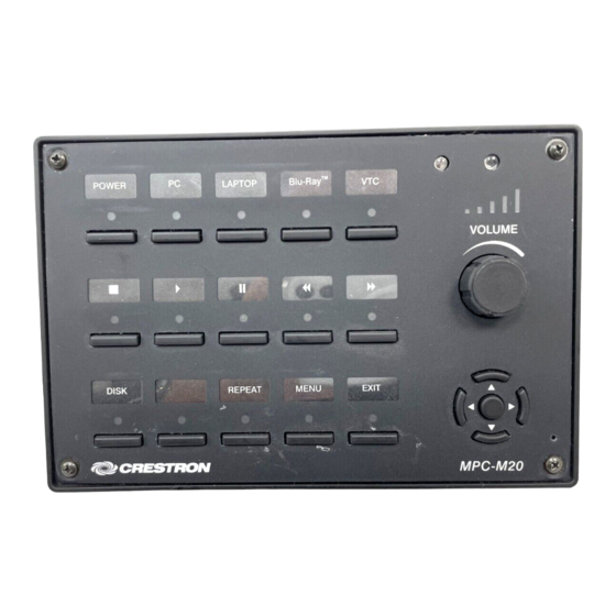
MPC-M10/MPC-M20/MPC-M25
MPC Media Presentation Controller
DO
Install the Device
The MPC-M10, MPC-M20, and MPC-M25 media presentation controllers
are designed to install into a standard 3-gang electrical box. After the
facility control network has been installed and verified, use the following
procedure to install the device.
NOTE:
The MPC-M10, MPC-M20, and MPC-M25 are functionally similar,
and they share the same installation and programming process. For
simplicity within this guide, the term "MPC device" is used except where
noted.
Attach the Mounting Plate into an Electrical Box
1. Turn the system power off.
2. Use the four included 6-32 x 3/4" screws to attach the mounting plate
to the electrical box.
Ground
wire
Mounting
plate
(4): 6-32 x 3/4"
Screws
3. Attach the mounting plate ground wire to an earth ground.
NOTE:
Ensure the unit is properly grounded.
Connect the Device
Route all appropriate cables through the electrical box, and then attach
them to the rear of the MPC device.
NOTE:
All cable connections must be made prior to attaching the MPC
device to the mounting plate.
NET:
LAN:
To any Cresnet
®
10/100Base-T Ethernet to
network device
LAN or web
COM:
RELAYS:
IR:
To any RS-232
To controllable
To IRP2 or
From digital or
device
devices
serial devices
analog devices
When making connections to the MPC device, note the following:
• Use Crestron
power supplies for Crestron equipment.
®
• Apply power after all connections to the device have been made.
• The included power cable cannot be extended.
NOTE:
COM 2, IR 2, and RELAYS 3, 4, 5, and 6 are found only on the
MPC-M25.
NOTE:
When connecting the included power supply to the NET connector
on the unit, make sure the lead with the white stripes connects to the
terminal marked "24." The other lead connects to the terminal marked "G."
DO
Check the Box
QUANTITY
PRODUCT
2
Connector, Butt Splice
1
Plate, Mounting
1
Power Cord, 6' 7" (2 m)
1
Power Pack, 24 Vdc 0.75 A, 100-240 Vac
2
Screw, 4-40 x 1/4", Pan Head, Phillips
4
Screw, 6-32 x 3/4", Truss Head, Combo
1
Tool, 1/16" Allen Wrench, L-shape, 3" Blade
For MPC-M10-W, MPC-M20-W, MPC-M25-W only
1
Labels, Sources, 100 Piece Set
1
Labels, Actions, 100 Piece Set
4
Screw, 4-40 x 1/2", Button Head, Hex
For MPC-M10-B-T, MPC-M20-B-T, MPC-M25-B-T only
1
Labels, Sources, 100 Piece Set
1
Labels, Actions, 100 Piece Set
4
Screw, 4-40 x 1/2", Button Head, Hex
For MPC-M10-W and MPC-M10-B-T only
1
Front Panel and Label, 10 Button
1
Front Panel and Label, 10 Button
For MPC-M20-W and MPC-M20-B-T only
1
Front Panel and Label, 20 Button
1
Front Panel and Label, 20 Button
For MPC-25-W and MPC-25-B-T only
1
Front Panel and Label, 20 Button
1
Front Panel and Label, 20 Button
Depending on the application, the MPC device INPUTS can be wired multiple ways. Refer to the following diagrams when wiring INPUTS.
WARNING:
Incorrect wiring may damage the MPC device.
INPUTS:
NOTE:
The settings for the pull-up resistor are specified in the SIMPL Windows program. For more information, refer to the SIMPL Windows help file.
Input Wiring Diagrams - Digital Input Function
Detecting a contact closure
Detecting a contact voltage
from a switch or relay
from a switch or relay
1
2
3
4
G
1
2
3
Analog input pull-up
Analog input pull-up
resistor: disabled
resistor: enabled
COLOR
Red
White
White
Black
Black
Black
White
Black
White
Black
White
Black
Input Wiring Diagrams - Analog Input Function
Reading voltage from
Reading resistance
an analog source
of a potentiometer
10 Vdc
+
+
+
-
-
-
24 Vdc
max
1
2
3
4
G
1
2
4
G
Analog input pull-up
Analog input pull-up
resistor: disabled
resistor: enabled
PART NUMBER
2021836
4506280
2001134
2045852
2007156
2009211
2022867
4509400
4509402
2021396
4509401
4509403
2021395
4506184
4506185
4506180
4506181
4506178
4506179
3
4
G
Advertisement
Table of Contents

Related Manuals for Crestron MPC-M20


Summary of Contents for Crestron MPC-M20
- Page 1 Install the Device Connect the Device Screw, 4-40 x 1/4", Pan Head, Phillips 2007156 The MPC-M10, MPC-M20, and MPC-M25 media presentation controllers Route all appropriate cables through the electrical box, and then attach Screw, 6-32 x 3/4", Truss Head, Combo 2009211 are designed to install into a standard 3-gang electrical box.
- Page 2 Crestron, the Crestron logo, Cresnet, Crestron Toolbox, and the MPC logo are either trademarks or registered trademarks of Crestron Electronics, Inc., in the United States and/or other countries.
Need help?
Do you have a question about the MPC-M20 and is the answer not in the manual?
Questions and answers