
Subscribe to Our Youtube Channel
Related Manuals for Crestron FT-PWR


Summary of Contents for Crestron FT-PWR
- Page 1 Crestron FT-PWR-B & FT-PWR-BALUM FlipTop Power Center Operations & Installation Guide...
- Page 2 This document was prepared and written by the Technical Documentation department at: Crestron Electronics, Inc. 15 Volvo Drive Rockleigh, NJ 07647 1-888-CRESTRON All brand names, product names and trademarks are the property of their respective owners. ©2006 Crestron Electronics, Inc.
-
Page 3: Table Of Contents
Crestron FT-PWR-B & FT-PWR-BALUM Contents FlipTop Power Center: FT-PWR-B & FT-PWR-BALUM Introduction ... 1 Features and Functions ... 1 Applications... 1 Specifications ... 2 Physical Description... 2 Industry Compliance ... 6 Setup ... 7 Installation ... 7 Hardware Hookup ... 11 Operation ... -
Page 5: Operations & Installation Guide – Doc
Introduction Features and Functions Applications The FT-PWR-B and FT-PWR-BALUM provide an elegant connectivity solution in a stylish flush mount tabletop package. Beneath the "FlipTop" lid, the cable storage compartment keeps installed interface cables (not included) at the ready for plugging in computers, AV sources, communication, control, or data cable. -
Page 6: Specifications
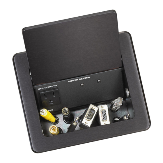
FlipTop Power Center Specifications Specifications for the FT-PWR-B and FT-PWR-BALUM are listed in the following table. FT-PWR-B and FT-PWR-BALUM Specifications Physical Description This section provides information on the connections, controls, and indicators available on your FT-PWR-B and FT-PWR-BALUM. FT-PWR-B and FT-PWR-BALUM Physical View NOTE: Cables not included. - Page 7 Crestron FT-PWR-B & FT-PWR-BALUM FT-PWR-B and FT-PWR-BALUM Overall Dimensions – Top View (14.50 cm) FT-PWR-B and FT-PWR-BALUM Overall Dimensions – Front View Operations & Installation Guide – DOC. 6480 5.08 in (12.90 cm) 5.71 in 6.75 in (17.15 cm) 5.38 in (13.67 cm)
- Page 8 FlipTop Power Center Crestron FT-PWR-B & FT-PWR-BALUM FT-PWR-B and FT-PWR-BALUM Overall Dimensions – Side View 2.38 in (6.05 cm) 5.33 in (13.54 cm) 4.56 in (11.58 cm) 4.64 in (11.79 cm) 5.21 in (13.32 cm) 4 • FlipTop Power Center FT-PWR-B & FT-PWR-BALUM...
- Page 9 125 VAC at 60 Hz. Connect the six-foot (183 cm) grounded AC line cord to supply AC power to the outlet on the topside of the FT-PWR-B and FT-PWR-BALUM. FlipTop Power Center: FT-PWR-B & FT-PWR-BALUM • 5 FlipTop Power Center DESCRIPTION...
-
Page 10: Industry Compliance
FlipTop Power Center Industry Compliance As of the date of manufacture, the FT-PWR-B and FT-PWR-BALUM have been tested and found to comply with specifications for CE marking and standards per EMC and Radiocommunications Compliance Labelling. NOTE: This device complies with part 15 of the FCC rules. Operation is subject to... -
Page 11: Setup
Tools required Parts Supplied for Cable Management Kit The cable support plate should be installed before mounting the FT-PWR-B or FT-PWR-BALUM to a surface. The cables are looped through the cable support plate. - Page 12 NOTE: Ensure that any cables you install have sufficient clearance to enable smooth movement. Mounting to Surface The FT-PWR-B and FT-PWR-BALUM are designed to mount in a horizontal surface, such as a desk top, lectern, or podium. The following diagram illustrates the required opening size to accommodate the FT-PWR-B and FT-PWR-BALUM. Use the supplied template to make the cutout.
- Page 13 These will be used to secure the front and rear mounting brackets. 2. Position the FT-PWR-B or FT-PWR-BALUM in the mounting hole. FlipTop Power Center: FT-PWR-B & FT-PWR-BALUM • 9 FlipTop Power Center...
- Page 14 FlipTop Power Center Mounting Bracket Screw Locations Mounting Bracket Installation CAUTION: Do not over-tighten the #10 screws as this may damage the surface and/or the unit. 10 • FlipTop Power Center FT-PWR-B & FT-PWR-BALUM Crestron FT-PWR-B & FT-PWR-BALUM #6-32 Screws Surface Cutout 3.
-
Page 15: Hardware Hookup
Operations & Installation Guide – DOC. 6480 FOUR #10-32 2"L SCREWS TWO MOUNTING BRACKETS FlipTop Power Center: FT-PWR-B & FT-PWR-BALUM • 11 FlipTop Power Center 7.210 in (18.31 cm) EIGHT #6-32 3/16"L... -
Page 16: Operation
AV, communication, data or control cables to be instantly available for connection to your devices. The recessed compartment also contains a three-pronged, grounded AC socket. 12 • FlipTop Power Center FT-PWR-B & FT-PWR-BALUM Crestron FT-PWR-B & FT-PWR-BALUM Operations & Installation Guide – DOC. 6480... -
Page 17: Problem Solving
For assistance in your local time zone, refer to the Crestron website (http://www.crestron.com/) for a listing of Crestron worldwide offices. You can also log onto the online help section of the Crestron website to ask questions about Crestron products. First-time users will need to establish a user account to fully benefit from all available features. -
Page 18: Return And Warranty Policies
Purchasers should inquire of the dealer regarding the nature and extent of the dealer's warranty, if any. CRESTRON shall not be liable to honor the terms of this warranty if the product has been used in any application other than that for which it was intended, or if it has been subjected to misuse, accidental damage, modification, or improper installation procedures. - Page 19 Crestron FT-PWR-B & FT-PWR-BALUM FlipTop Power Center This page is intentionally left blank. FlipTop Power Center: FT-PWR-B & FT-PWR-BALUM • 15 Operations & Installation Guide – DOC. 6480...
- Page 20 Crestron Electronics, Inc. Operations & Installation Guide – DOC. 6480 15 Volvo Drive Rockleigh, NJ 07647 (2014987) Tel: 888.CRESTRON 05.06 Fax: 201.767.7576 Specifications subject to www.crestron.com change without notice.
Need help?
Do you have a question about the FT-PWR and is the answer not in the manual?
Questions and answers