Table of Contents
Advertisement
Quick Links
DO
GUIDE
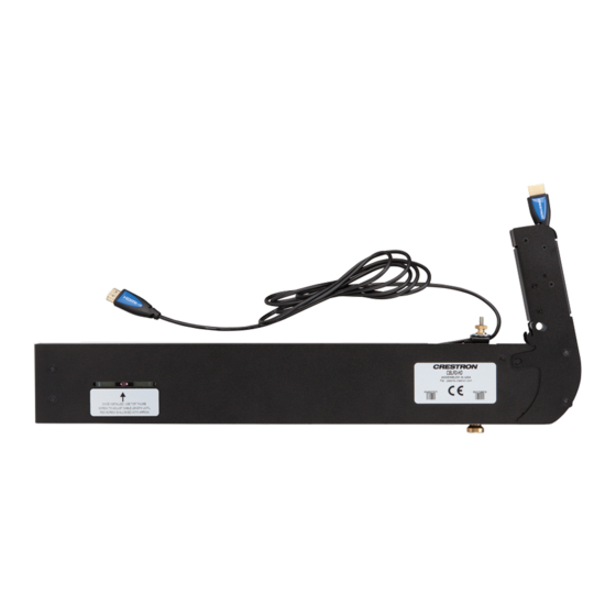
CBLR2 Series
Cable Retractors for FlipTops
TM
DO
Prepare the FlipTop
Preparation of the Crestron
FlipTop™ consists of the following:
®
• Modifying the FlipTop assembly to accommodate the cable retractors
• Determining the desired mounting orientation (Retractors are shipped configured for vertical
orientation, but are easily reconfigured for horizontal orientation.)
NOTE:
The CBLR2-DP-V and CBLR2-DP-H models are dedicated to vertical and horizontal
orientation, respectively.
NOTE:
For preparation of the FlipTop 600 Series models, refer to "Modify the FlipTop (FlipTop 600
Series Models)."
Modify the FlipTop (Excludes FlipTop 600 Series Models)
1. Remove four screws (A) to detach the lower bar assembly. Also remove two screws (B). Retain
screws A and B to attach the FlipTop mounting bracket assembly. Refer to the FlipTop mounting
brackets table provided in the "DO Check the Accessories" section on the next page to ensure
that the mounting bracket received is appropriate for the FlipTop being modified.
2. Remove four screws (C) to detach the cable guide. Retain the screws to attach the two side filler
plates (sold separately).
Screws (C)
Cable
Guide
Screw (B)
Screws (A)
Screw (B)
Lower Bar
Assembly
3. Move the mounting bracket assembly up into position and secure it using four screws (A) and two
screws (B) removed in step 1.
Screws (C)
Side Filler
Plates
Screw (B)
Screws (A)
Mounting
Screw (B)
Bracket
Assembly
4. Position the side filler plates and secure them using four screws (C).
Side Filler Plates
Modify the FlipTop (FlipTop 600 Series Models)
Retractors can be installed in both the left and right sides of the FlipTop 600 Series models.
1. Remove the screw (C) holding the cable guide in place, and then remove the cable guide.
2. Remove the screws (D) holding the cable pass-through bracket in place, and then remove the
cable pass-through bracket.
3. Remove the shoulder screws from the front of the unit. Save these as they are used in retractor
installation.
Screws (C)
Cable Guide
Cable Pass-Through Bracket
Screws (D)
Shoulder Screws
Reconfigure the Retractors for Horizontal Operation
NOTE:
The CBLR2-DP-V and CBLR2-DP-H models are dedicated to vertical and horizontal
orientation, respectively.
To reconfigure the retractors for horizontal orientation, refer to the following illustrations and perform
these steps:
1. Remove the four screws (E), two from each side of the retractor, that attach the neck in the vertical
orientation.
Mounting
Bracket
Assembly
Side View
(4) Screws (E)
(Two on Each Side)
Retractor Neck
2. Reposition the neck as shown in the horizontal orientation view and attach it using the four screws
(E) to secure the neck in that position.
Retractor Neck
Side View
(4) Screws (E)
(Two on Each Side)
DO
Adjust the Retractor
Once the retractor arm configuration is set, refer to the following illustration and adjust the retractor
arm tension and cable retraction speed as follows:
1. Adjust the retractor tension by loosening the top thumb screw enough to enable pulling or pushing
of the adjacent cable end. Align the red screw with the label arrow.
2. Adjust the cable retraction speed.
a. Pull the knob outward and move it to the VERT or HORZ position to match the configuration
of the retractor arms.
b. Pull the cable (plug end) out so it is fully extended.
c. Pull the cable a second time to cause it to retract, and observe the speed of the cable
retraction. If it is too slow or too fast, reposition the knob to an intermediate position and
recheck.
Thumb Screw
Red Screw
Once installed, use the top thumb screw
Cable Retraction
to adjust the cable length until the red
Speed Adjustment
screw is aligned with the arrow.
Cable End
VERT
HORZ
Knob
Slow
Fast
Advertisement
Table of Contents

Related Manuals for Crestron CBLR2 Series


Summary of Contents for Crestron CBLR2 Series
- Page 1 4. Position the side filler plates and secure them using four screws (C). 2. Reposition the neck as shown in the horizontal orientation view and attach it using the four screws (E) to secure the neck in that position. Preparation of the Crestron FlipTop™ consists of the following: ®...
- Page 2 Crestron, the Crestron logo, FlipTop, and FlipTops are either trademarks or registered trademarks of Crestron Electronics, Inc. in the United States and/or other countries.
Need help?
Do you have a question about the CBLR2 Series and is the answer not in the manual?
Questions and answers