Advertisement
DM-8G-CONN-100 and DM-8G-CRIMP
DigitalMedia 8G™ Connectors and Crimper
Introduction
1
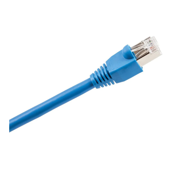
DM-8G-CONN-100 and DM-8G-CRIMP are used to
®
terminate Crestron
DigitalMedia 8G™ cable
(DM-CBL-8G):
● DM-8G-CONN-100 contains 100 RJ-45 shielded
modular plug connectors. As shown in the illustration
below, a DM-8G-CONN connector is comprised of a
housing, a load bar, and a plug shield. A boot
provides a protective covering and strain relief for
the connector.
Plug Shield
Load Bar
Housing
● DM-8G-CRIMP (sold separately
from DM-8G-CONN-100) is a
tool that allows hand crimping of
the DM-8G-CONN connector
for proper cable termination.
Additional items (not supplied) required for termination
of the DM-CBL-8G cable are the following:
● Wire or diagonal cutter
● Razor knife or scissors
2
Preparing the Cable
A sectional view of DM-CBL-8G shielded twisted pair
(STP) cable is shown below.
Cable
Foil
Inner
Jacket
Shield
Jacket
Drain
Wire
1
QUICKSTART DOC. 7064B (2028626)
To prepare the cable for termination, do the following:
CAUTION: Do not nick the insulation of the wires or the
!
foil shield of the cable.
1. Slide the boot over the end of the cable.
Boot
2. Strip the cable jacket 1½ inches (38 mm) from the end
of the cable.
3. Fold back the foil shield so that it lies smoothly over the
cable jacket.
NOTE: If the cable you are using has a wire braid, fold
back the braid over the cable jacket and then fold back
the foil sheid over the braid.
4. Fold back the drain wire over the foil shield.
5. Cut and remove the white inner jacket.
(4) Wire
NOTE: If the cable you are using has a clear plastic
Pairs
wrap instead of a white inner jacket, cut and remove
the plastic wrap.
www.crestron.com
©2011 Specifications subject to
02.11
change without notice.
6. Slide the plug shield over the drain wire and foil shield
past the stripped end of the cable jacket.
CAUTION: The foil shield should be visible on both sides
!
of the plug shield. Do not slide the plug shield past the
back end of the foil shield.
1½ in
Positioning the Cable
1
3
(38 mm)
To position the cable for insertion into the connector,
do the following:
1. Untwist each of the four twisted wire pairs.
2. Straighten and arrange the orange, blue, and brown
wire pairs, and then fold back the green wire pair.
3. Insert the orange,
blue, and brown
wire pairs through
the load bar, and
then insert the
green wire pair
into the slot of
the load bar.
888.273.7876
201.767.3400
All brand names, product names, and trademarks
are the property of their respective owners.
G/W
G
Br
O/W = Orange/White
Bl = Blue
O = Orange
Bl/W = Blue/White
Br/W = Brown/White
G/W = Green/White
Br = Brown
G = Green
Green Pair
Orange
Pair
Blue Pair
O/W
O
Bl
Bl/W
Br/W
Brown
Pair
Advertisement
Table of Contents

Related Manuals for Crestron DM-8G-CONN-100


Summary of Contents for Crestron DM-8G-CONN-100
- Page 1 To prepare the cable for termination, do the following: 6. Slide the plug shield over the drain wire and foil shield past the stripped end of the cable jacket. DM-8G-CONN-100 and DM-8G-CRIMP are used to CAUTION: Do not nick the insulation of the wires or the ®...
- Page 2 DM-8G-CONN-100 and DM-8G-CRIMP DigitalMedia 8G™ Connectors and Crimper Positioning the Cable (Continued) 7. Visually verify that all c. While holding the assembly, carefully close the tool wires are fully inserted handles until the ratchet releases, and then allow 4. Arrange the wire pairs for T568B termination.
Need help?
Do you have a question about the DM-8G-CONN-100 and is the answer not in the manual?
Questions and answers