airquee Last One Standing Additional Operating Instructions
Hide thumbs
Also See for Last One Standing:
- Additional operating instructions (48 pages) ,
- Operating instructions manual (16 pages) ,
- Additional operating instructions (16 pages)
Table of Contents
Advertisement
Quick Links
1. Site Survey........................................................................................ 2
2. Inflatable Inclusions ........................................................................... 3
3. Intended use of product .................................................................... 3
4. Operating guidelines ......................................................................... 4
5. Troubleshooting ................................................................................ 4
6. Hazards relating to electrical equipment ........................................... 5
7. Setup ................................................................................................ 5
7.1 Assembly of the mechanism ..................................................... 6
7.2 Adding the sealed tube ............................................................. 8
7.3 Assembly of the bed ................................................................. 9
7.4 Assembly of the Control Panel ................................................. 10
7.4.1 The Control Box ............................................................. 10
7.4.2 Transporting and storing ................................................. 10
7.4.3 Positioning of the control panel ....................................... 11
8.1 Routine Inspections ................................................................... 11
8.2 Trial runs ................................................................................... 12
8.3 Thorough examination ............................................................... 12
9. Spare Parts Codes ............................................................................ 12
Contents
Page 1 of 14
Advertisement
Table of Contents

Related Manuals for airquee Last One Standing


Summary of Contents for airquee Last One Standing
-
Page 1: Table Of Contents
Contents 1. Site Survey..................2 2. Inflatable Inclusions ................3 3. Intended use of product ..............3 4. Operating guidelines ................. 4 5. Troubleshooting ................4 6. Hazards relating to electrical equipment ........... 5 7. Setup ....................5 7.1 Assembly of the mechanism ............. 6 7.2 Adding the sealed tube ............. -
Page 2: Site Survey
YOUR OWN RISK ASSESSMENT BEFORE ATTEMPTING TO USE THIS PRODUCT. . Site survey: 1. Carry out a survey of the area where the Last One Standing will be located, and check for any overhead/underground cables. It’s important that this is carried out to avoid ground anchors penetrating underground services, and the Last One Standing coming into contact with overhead cables when inflated. -
Page 3: Intended Use Of Product
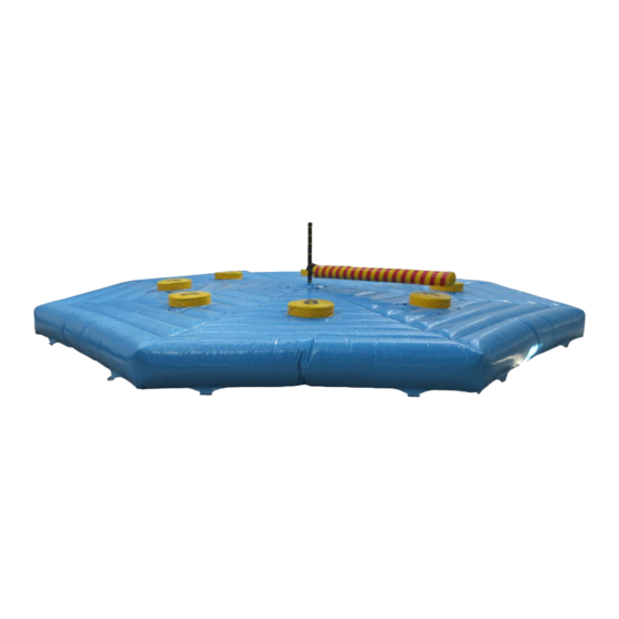
Intended use of the product: The Last One Standing with Single Arm Mechanism is designed to be used by up to eight players and one operator. The players must jump at the right time to avoid the rotating sealed arm. -
Page 4: Troubleshooting
The unit should NOT TO BE USED IF IT BECOMES WET. In the event of rain, the unit should be deflated and folded to prevent water collecting on it. The Emergency Stop button MUST ALWAYS BE DEPRESSED AND THE KEY REMOVED whenever you are setting up the ride or leaving the control console unattended. -
Page 5: Hazards Relating To Electrical Equipment
The motor will give an error code if the input voltage is too high. Overvoltage: Make sure you change the generator to a smaller one. If you still have issues with the mechanism, please contact Airquee customer support on the following number +44 (0)1179 414 918. To avoid getting an error code: Make sure the electric power supply is stable and not fluctuating in any way. - Page 6 The mechanism consists of: Sealed Tube Drive Motor Bed Hole Drive Motor Spring Cover with PVC cover Cover Cover AP2963 AP2786 AP3149 AP3152 Metal Arm Middle Bar Wheels Legs Leg Covers MP0049 MP0022 MP0004 MP0003 AP3151 Place the drive motor cover on top of the drive motor, then insert the wheels and tighten them with the supplied bolts.
- Page 7 Exchange the wheels with the legs. MAKE SURE THE SURFACE WHERE YOU PLACE THE MECHANISM IS LEVEL! Insert the middle bar into the drive motor’s shaft and tighten the bolts at the desired height. We recommend the second and third holes at least.
-
Page 8: Adding The Sealed Tube
The spring has a screw thread, which allows it to be tightened manually. It will be easier if you loosen the spring before you add the metal arm to the middle bar. 7.2 Adding the sealed tube: DO NOT INFLATE THE SEALED TUBE BEFORE YOU SLIP IT ON THE ARM BAR! Slip the sealed tube on the metal arm, using the highlighted hole. -
Page 9: Assembly Of The Bed
Connect the drive motor to the control panel with the 12m cable. The electric socket can be found inside the drive motor. 7.3 Assembly of the bed: Start connecting the sandwich Velcro flaps. The easiest way to connect the flaps is to first patch the lower part of the Velcro all the way, then cover the top part of the right side soft Velcro with the left side hard Velcro flap. -
Page 10: Assembly Of The Control Panel
7.4 Assembly of the Control Panel: The Control Panel consists of: ON/OFF Triangle Control Box Support Bar Legs 12M Cable 3M Cable AP2785 MP0013 MP0012 MP0056 MP0015 MP0008 MP0009 You must bolt these 3 parts together to make it stable. 7.4.1 The Control Box: 1. -
Page 11: Positioning Of The Control Panel
After every setup or operation, before opening the game to the public, the controller or his nominee SHALL PERSONALLY CHECK that the setup of the Last One Standing is correct. We recommend to check for every criteria written below. The person carrying out the check shall be sufficiently trained or experienced in the check routines that have to be carried out. -
Page 12: Trial Runs
NOW ARE THE PLAYERS ALLOWED TO ENTER THE UNIT. 8.3 Thorough examination Besides the regular checks, the Last One Standing should be thoroughly examined at appropriate intervals by a competent person/institute/organization/company. The intervals between two successive thorough examinations may be governed by existing national... - Page 13 MP0031 - Middle Bar MP0027 - Allen Wrench To assemble\disassemble the mechanism. MP0029 - 13mm Wrench To assemble\disassemble the mechanism. To assemble\disassemble the mechanism, to connect the inflatable MP0030 - 19mm Wrench arm to the middle bar. MP0049 – 1M Metal Bar To hold the sealed tube.
- Page 14 Manual. It is the user's responsibility to determine whether there have been any such updates or amendments. Neither Airquee Ltd nor any of its directors, officers, employees or agents shall be liable in contract, tort or in any other manner whatsoever to any person for any loss, damage, injury, liability, cost or expense of any nature, including without limitation incidental, special, direct or consequential damages arising out of or in connection with the use of the Manual.
Need help?
Do you have a question about the Last One Standing and is the answer not in the manual?
Questions and answers