airquee Last One Standing Operating Instructions Manual
Hide thumbs
Also See for Last One Standing:
- Additional operating instructions (48 pages) ,
- Additional operating instructions (14 pages) ,
- Additional operating instructions (16 pages)

Subscribe to Our Youtube Channel
Related Manuals for airquee Last One Standing


Summary of Contents for airquee Last One Standing
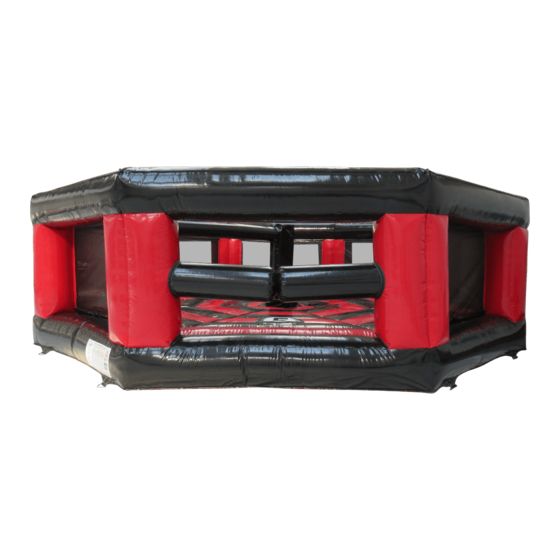
- Page 1 Last One Standing with 2 arms different levels mechanism IMPORTANT AS OWNER/OPERATOR IT IS YOUR RESPONSIBILITY TO WRITE AND CARRY OUT YOUR OWN RISK ASSESSMENT BEFORE ATTEMPTING TO USE THIS PRODUCT.
-
Page 2: Table Of Contents
Contents 1. Site Survey..................1 2. Inflatable Inclusions ................1 3. Intended Use of Product ..............1 4. Operating Guidelines/Rules of Play ........... 2 5. Troubleshooting ................3 6. Hazards Relating to Electrical Equipment ......... 4 7. Setting Up ..................4 7.1 Assembly of the Mechanism ............. -
Page 3: Site Survey
1. Site Survey 1. Carry out a survey of the area where the Last One Standing will be located, and check for any overhead/underground cables. It’s important that this is carried out to avoid ground anchors penetrating underground services, and the Last One Standing coming into contact with overhead cables when inflated. -
Page 4: Operating Guidelines/Rules Of Play
Different setups of the mechanism: 4. Operating Guidelines/Rules of Play Before entering the game area, CLEAR INSTRUCTIONS SHALL BE GIVEN to players on their conduct during playtime. NO SOMERSAULTS or any ACROBATICS allowed. All players remove footwear, eye wear, cell phones, keys, neck wear and/or any sharp items. DO NOT allow the users to OBSTRUCT THE MOVEMENT OF THE... -
Page 5: Troubleshooting
The motor will give an error code if the input voltage is too high. Overvoltage: Make sure you change the generator to a smaller one. For further support regarding your mechanism please contact Airquee at +44 (0)1179 414 918 or Tilda@airquee.co.uk. To avoid getting an error code: Make sure the electric power supply is stable and not fluctuating in any way. -
Page 6: Hazards Relating To Electrical Equipment
In accordance with HSE guidelines, all 240v equipment should be protected with an RCD (Residual Current Device) having a maximum trip current of 30 mA. RCD’s are available from Airquee or your electrical store. WHEN USING IT WITH A GENERATOR, MAKE SURE IT HAS AN OUTPUT OF MORE THAN 4 kVA, AND A STABLE 230V ON 50HZ. - Page 7 MAKE SURE THE MECHANISM CAUTION! IS NOT CONNECTED TO A POWER SOURCE WHEN ASSEMBLING IT! Add the Foam Cover to the Drive Motor, then insert the wheels and tighten them with the supplied bolts. Unfold the bed at the desired location and move the drive motor to the center of the bed.
- Page 8 DO NOT USE THE LOWEST HOLE BECAUSE IT MAY PRODUCE FRICTION BETWEEN THE MATERIALS! Connect the 2 Metal Arms: insert the arms into their corresponding hole and use the bolts to tighten them. USE THE SECOND HOLE, as shown on the images below. MAKE SURE THE BOLTS ARE TIGHT ENOUGH, BUT DO NOT OVERTIGHTEN THEM.
-
Page 9: Add The Sealed Arms
The bolt highlighted below regulates the Metal Arms capability to jump at a certain height. USE THE HOLE Add the Sealed Arms: DO NOT INFLATE THE SEALED ARMS BEFORE YOU SLIP IT ON THE ARMBARS! Slip the Sealed Arms on the Arm Bars, using the highlighted hole. -
Page 10: The Hand-Held Fan
The Hand-Held Fan READ THE MANUAL OF THE BLOWER SUPPLIED BY THE MANUFACTURER OF THE FAN BEFORE ATTEMPTING TO USE IT. IMPORTANT: DO NOT LEAVE THE SEALED ARM UNATTENDED WHILE INFLATING/DEFLATING AND DO NOT OVER INFLATE. The hand fan comes with an extra adapter for your valve on the sealed arms. This adaptor has 2 extra plastic pieces that you must take off. -
Page 11: The Control Panel
Inflation process: 1. Locate the valve and remove the cap. 2. Connect the pipe to the fan using the hole marked with “OUT”. 3. Connect the adaptor to the valve. 4. Switch ON the fan and inflate until firm to touch. 5. -
Page 12: The Bed
FIELD OF Positioning of the control panel: VIEW OPERATOR/ CONTROLLER The control panel must be placed at the entrance, at an approximate distance of 1.5M, so that the operator has an unobstructed view of ALL the players. ENTRANCE The Bed: Connect the Drive Motor to the Control Panel with the 12 Meter Cable. -
Page 13: Transporting/Storing The Unit
You may inflate the bed. While inflating, adjust the position of the bed around the mechanism with the help of the anchor points, to make sure the mechanism stands in the middle of its designated hole. After inflating, add the Bed Hole Cover. Add the foam cover to the middle bar. -
Page 14: Routine Inspections, Trial Operations And Thorough Examinations
NOW ARE THE PLAYERS ALLOWED TO ENTER THE UNIT. Thorough Examination Besides the regular checks, the Last One Standing should be thoroughly examined at appropriate intervals by a competent person/institute/organization/company. The intervals between two successive thorough examinations may be governed by existing national regulations: 10. -
Page 15: Spare Part Codes
11. Spare Part Codes: Code and Name Description MP0002 - Shock Absorber Spring Holds and adjusts the height of the inflatable arm. MP0003 - Drive Motor Leg Stabilizes the Drive Motor. For moving the mechanism. MP0004 - Drive Motor Wheel To fix the Legs to the base of the Drive Motor and to adjust the MP0005 - 10 x 30 mm bolt height of the Arm Bars. - Page 16 Additional Manual. All logos, images and content not owned by Airquee Ltd are copyright to their respective owners and have been reproduced by permission.
Need help?
Do you have a question about the Last One Standing and is the answer not in the manual?
Questions and answers