H3C WX5540H Installation Manual
Hide thumbs
Also See for WX5540H:
- User configuration manual (57 pages) ,
- Configuration manual (11 pages) ,
- Installation, quick start (4 pages)

Related Manuals for H3C WX5540H


Summary of Contents for H3C WX5540H
- Page 1 H3C WX5540H Access Controller Installation Guide New H3C Technologies Co., Ltd. http://www.h3c.com.hk Document version: 6W102-20170421...
- Page 2 Copyright © 2015-2017, New H3C Technologies Co., Ltd. and its licensors All rights reserved No part of this manual may be reproduced or transmitted in any form or by any means without prior written consent of New H3C Technologies Co., Ltd.
- Page 3 Preface The H3C WX5540H Access Controller Installation Guide describes preparing for installation, installing the access controller, troubleshooting, and hardware management and maintenance of the WX5540H access controller. This preface includes the following topics about the documentation: Audience. • Conventions. •...
- Page 4 GUI conventions Convention Description Window names, button names, field names, and menu items are in Boldface. For Boldface example, the New User window opens; click OK. > Multi-level menus are separated by angle brackets. For example, File > Create > Folder. Symbols Convention Description...
- Page 5 It is normal that the port numbers, sample output, screenshots, and other information in the examples differ from what you have on your device. Obtaining documentation To access the most up-to-date H3C product documentation, go to the H3C website at http://www.h3c.com.hk. To obtain information about installation, configuration, and maintenance, click http://www.h3c.com.hk/Technical_Documents...
-
Page 6: Table Of Contents
Contents Preparing for installation ············································································································································· 1 Safety recommendations ·················································································································································· 1 Safety symbols ·························································································································································· 1 General safety recommendations ··························································································································· 1 Electrical safety ························································································································································· 1 Laser safety ································································································································································ 2 Examining the installation site ········································································································································· 2 Temperature and humidity ·······································································································································... - Page 7 Hardware management and maintenance ·············································································································· 29 Displaying hardware information for the device ········································································································ 29 Displaying software and hardware version information for the device ·························································· 29 Displaying operational statistics for the device ·································································································· 30 Displaying detailed information about the device ····························································································· 31 ...
-
Page 8: Preparing For Installation
Preparing for installation Safety recommendations Safety symbols When reading this document, note the following symbols: WARNING means an alert that calls attention to important information that if not understood or followed can result in personal injury. CAUTION means an alert that calls attention to important information that if not understood or followed can result in data loss, data corruption, or damage to hardware or software. -
Page 9: Laser Safety
Do not work alone when you operate the device with the device powered on. • • Always check that the power has been disconnected when you perform operations that require the device to be powered off. Laser safety WARNING! Do not stare into any fiber port when the device is powered on. The laser light emitted from the optical fiber might hurt your eyes. -
Page 10: Cooling
The device uses left to right airflow for heat dissipation. Plan the installation site for adequate ventilation. • H3C recommends that you leave a minimum of 10 cm (3.94 in) of clearance around the air vents. Make sure the rack or workbench has a good ventilation system. -
Page 11: Emi
Always wear an ESD wrist strap. Make sure the wrist strap makes skin contact and is reliably • grounded when installing the transceiver module. The ESD wrist strap is not provided with the device. Order it yourself. To attach an ESD wrist strap: Wear the wrist strap on your wrist. -
Page 12: Lightning Protection
Keep the device far away from radio transmitting stations, radar stations, and high-frequency • devices. Use electromagnetic shielding, for example, shielded interface cables, when necessary. • Lightning protection To better protect the device from lightning, follow these guidelines: Make sure the grounding cable of the chassis is reliably grounded. •... - Page 13 Item Requirements Result • The equipment and rack are reliably grounded. • The equipment room is dust-proof. • The humidity and temperature are at acceptable levels. • Wear an ESD wrist strap. Make sure the wrist strap makes good skin contact and is reliably grounded ESD prevention when installing FRUs.
-
Page 14: Installing The Device
WARNING! Keep the tamper-proof seal on a mounting screw on the chassis cover intact, and if you want to open the chassis, contact H3C Support for permission. Otherwise, H3C will not be liable for any consequence caused thereby. Confirming installation preparations Before you install the device, verify that you have read "Preparing for... -
Page 15: Installation Flow
Installation flow Figure 3 Installation flow Mounting the device on a workbench If a standard 19-inch rack is not available, you can place a device on a clean, flat workbench, as follows: Clean the recessed areas on the chassis bottom. Attach the four rubber feet to the recessed areas on the chassis bottom. -
Page 16: Installing The Device In A 19-Inch Rack
Figure 4 Mounting the device on a workbench Installing the device in a 19-inch rack You can install the device in a 19-inch rack by using the following methods: Installing the device by using front and rear mounting brackets. • Installing the device by using front mounting brackets and a rack shelf. -
Page 17: Installing The Device By Using Front And Rear Mounting Brackets
Installing the device by using front and rear mounting brackets Wear the ESD wrist strap and make sure the rack is sturdy and is reliably grounded. Use a front mounting bracket to mark the cage nut installation position on the front rack posts. Install cage nuts. - Page 18 Figure 9 Installing the weight-bearing screws According to the device installation position in the rack, use screws and cage nuts to attach the rear mounting brackets to the rear rack posts. Figure 10 Installing rear mounting brackets Supporting the bottom of the device with one hand and holding the front of the device with the other, place the device slowly in the rack.
-
Page 19: Installing The Device By Using Front Mounting Brackets And A Rack Shelf
Figure 11 Installing the device in the rack Installing the device by using front mounting brackets and a rack shelf The rack shelf is an optional component that needs to be separately ordered if needed. The rack shelf in this example is for illustration only. To install the device by using front mounting brackets and a rack shelf: Wear the ESD wrist strap and verify that the rack is sturdy and is reliably grounded. -
Page 20: Installing The Device By Using Front Mounting Brackets And Slide Rails
Figure 12 Installing the rack shelf Place the device on the rack shelf and push the device in the rack. Attach the front mounting brackets on the device to the front rack posts by using screws and cage nuts, as shown in Figure Figure 13 Installing the device in the rack Installing the device by using front mounting brackets and slide... - Page 21 To install the device by using front mounting brackets and slide rails: Wear the ESD wrist strap and verify that the rack is sturdy and is reliably grounded. Use the screws supplied with the front mounting brackets to attach the front mounting brackets to the device, as shown in Figure Attach the slide rails to the rack.
-
Page 22: Grounding The Device
Attach the front mounting brackets on the device to the front rack posts with M6 screws and cage nuts. NOTE: Keep a minimum distance of 1 U (44.45 mm, or 1.75 in) between devices for heat dissipation. Grounding the device WARNING! •... - Page 23 Figure 17 Grounding the device with the rack (1)
- Page 24 Figure 18 Grounding the device with the rack (2) Grounding the device with a grounding conductor buried in the earth—If earth is available at the installation site, hammer a 0.5 m (1.64 ft) or longer angle iron or steel tube into the earth to serve as a grounding conductor.
-
Page 25: Installing A Lightning Protector For A Network Port
Installing a lightning protector for a network port A lightning protector is not provided with the device. H3C recommends that you install a lightning protector for 10/100/1000 Mbps RJ-45 copper Ethernet ports. IMPORTANT: Before installing the lightning protector, read the instructions that come with the lightning protector. -
Page 26: Precautions
Precautions If the performance of the port lightning protector is adversely affected in the following situations, follow the recommended solution: • Problem 1—The port lightning protector is installed in reverse direction. Solution—Connect the Surge end to the outdoor network cable and the Protect end to the network port on the device. - Page 27 Figure 21 Power strip with lightning protection • Steady green—The circuit is operating correctly. (1) Operating LED • Off—The circuit is damaged. Steayd red indicates a wrong wire connection (the wire is not grounded or (2) Grounding/pole detection LED the live line and null line are reversely connected), and you need to check the power supply line.
-
Page 28: Connecting The Ethernet Cables
Connecting the Ethernet cables Connecting a copper Ethernet port Connect one end of the Ethernet cable to the copper Ethernet port of the device, and the other end to the Ethernet port of the peer device. After powering on the device, examine the LEDs of the fixed copper Ethernet port. For more information about the LED description, see "Appendix B LEDs."... -
Page 29: Installing A Power Module
Figure 22 Connecting an optical fiber Power on the device, and examine the SFP port LEDs: If the LED is on, a fiber link has been set up. If the LED is off, no link has been set up. The reason might be wrong connection of the Tx and Rx ends. -
Page 30: Connecting The Ac Power Cord
Figure 23 Installing an AC power module Figure 24 Installing a DC power module Connecting the AC power cord CAUTION: Before powering on the device, connect the grounding cable of the device. To connect the AC power cord: Pivot the bail latch upward. Connect one end of the AC power cord to the AC-input power receptacle on the device. -
Page 31: Connecting The Dc Power Cord
Figure 25 Connecting an AC power cord Connecting the DC power cord Use a flat-blade screwdriver to remove the protection cover from the DC power module. Correctly insert the DC plug into the DC power receptacle. Use a flat-blade screwdriver to fasten the screws on the DC plug. Connect the other end of the DC power cord to the DC power source. -
Page 32: Verifying The Installation
Press Ctrl+T to start heavy memory test Booting Normal Extended BootWare The Extended BootWare is self-decompressing..Done. **************************************************************************** H3C WX5540H BootWare, Version 5.10 **************************************************************************** Copyright (c) 2004-2017 New H3C Technologies Co., Ltd. Compiled Date : Apr 21 2017 CPU Type : XLP432 CPU Clock Speed... - Page 33 Cryptographic Algorithms Known-Answer Tests passed. Line con0 is available. Press ENTER to get started. Press Enter at the prompt, and you can configure the device when the prompt <H3C> appears. During the startup process, the CPLD is automatically upgraded to the latest version.
-
Page 34: Troubleshooting
Verify that the power source is as required. Verify that the power cord is connected securely. Verify that the power cord is in good condition. If the problem persists, contact H3C Support. No display or garbled display on the configuration terminal... -
Page 35: Software Loading Failure
Verify that the console cable is in good condition. If the problem persists, contact H3C Support. Software loading failure Symptom The device fails in software loading. Solution To resolve the problem: Verify that the physical ports are connected securely and correctly. If a port is not connected securely, reconnect the port and make sure the connections are correct. -
Page 36: Hardware Management And Maintenance
H3C Comware Software, Version 7.1.064, ESS 5207 Copyright (c) 2004-2017 New H3C Technologies Co., Ltd. All rights reserved. H3C WX5540H uptime is 0 weeks, 1 day, 2 hours, 36 minutes Last reboot reason : User soft reboot Boot image: cfa0:/boot.bin Boot image version: 7.1.064, ESS 5207... -
Page 37: Displaying Operational Statistics For The Device
H3C Comware Software, Version 7.1.064, ESS 5207 Copyright (c) 2004-2017 New H3C Technologies Co., Ltd. All rights reserved. H3C WX5540H uptime is 0 weeks, 1 day, 2 hours, 57 minutes Last reboot reason : User soft reboot Boot image: cfa0:/boot.bin Boot image version: 7.1.064, ESS 5207... -
Page 38: Displaying Detailed Information About The Device
CPLD 2 Version is 002 FPGA1 Logic Version is 518 FPGA2 Logic Version is 518 Basic Bootrom Version is 5.06 Extend Bootrom Version is 5.10 [Subslot 0]H3C WX5540H Hardware Version is Ver.A ================================================ ===============display device verbose=============== Slot No. Subslot No. Board Type... -
Page 39: Displaying The Cpu Usage Of The Device
Use the display device manuinfo command to display the electronic label data for the device. <H3C>display device manuinfo Slot 1 CPU 0: DEVICE_NAME:WX5540H DEVICE_SERIAL_NUMBER:210235A1JT8888888888 MAC_ADDRESS:000f-e232-2223 MANUFACTURING_DATE:2017-04-08 VENDOR_NAME:H3C Table 6 Command output Field Description DEVICE_NAME Device model. DEVICE_SERIAL_NUMBER Serial number of the device. -
Page 40: Displaying The Operational Status Of The Built-In Fans
Swap Swap memory. Displaying the operational status of the built-in fans Use the display fan command to display the operating states of fans. <H3C>display fan Fan 1 State: Normal Fan 2 State: Normal Fan 3 State: Normal Fan 4 State: Normal... -
Page 41: Displaying The Operating State Of A Power Module
To avoid a reboot failure, use the boot-loader file command to specify a new startup software image. For more information about the display startup and display boot-loader commands, see H3C WX5540H Access Controller Fundamentals Command Reference. -
Page 42: Configuration Procedure
Configuration procedure Rebooting the device immediately Task Command Remarks Reboot the device immediately. reboot [ force ] Available in user view. Scheduling a reboot for the device Task Command Remarks Use either command. By default, no reboot date or time •... -
Page 43: Appendix A Chassis Views And Technical Specifications
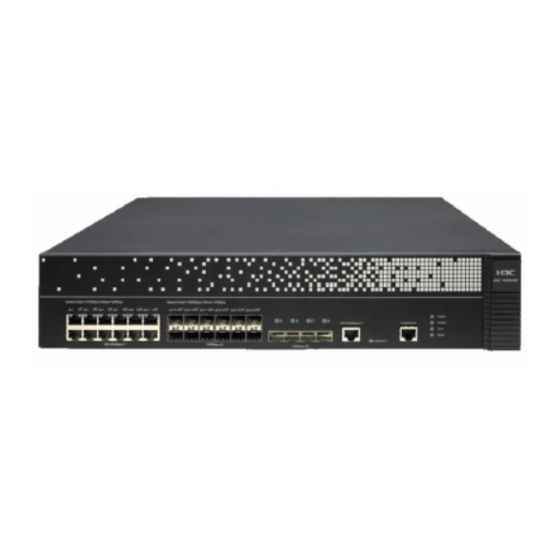
Appendix A Chassis views and technical specifications The figures in this document are for illustration only. Chassis views Figure 27 Front view (1) 100/1000BASE-T autosensing Ethernet ports 1 through 12 (2) 100BASE-FX/1000BASE-X SFP ports 13 through 24 (3) 10GBASE-R SFP+ ports 25 through 28 (4) 100/1000 BASE-T management Ethernet port (5) Console port Figure 28 Rear view... -
Page 44: Power Module Views
Power module views AC power module Figure 29 AC power module (1) Captive screw (2) Power switch (3) Air outlet vent (4) Power receptacle DC power module Figure 30 DC power module (1) Captive screw (2) Power switch (3) Air outlet vent (4) Power receptacle Transceiver module, fiber connector, and optical fiber views... -
Page 45: Technical Specifications
Figure 31 SFP transceiver module Figure 32 SFP+ transceiver module Figure 33 A pair of optical fibers that uses an LC connector (1) LC connector (2) Optical fiber Technical specifications Table 11 Technical specifications Item Specification Console port One, 9600 bps (default) to 115200 bps Gigabit Ethernet port 12 ×... -
Page 46: Transceiver Module Specifications
Item Specification Memory 4 × 8 GB DDR3 Storage media 4 GB CF card Dimensions (H × W × D) (excluding rubber feet 88.1 × 440 × 480 mm (3.47 × 17.32 × 18.90 in) and mounting brackets) Rate AC voltage range 100 VAC to 240 VAC @ 50 Hz or 60 Hz Rate DC voltage range –48 VDC to –60 VDC... - Page 47 Item Specification Receive sensitivity ≤ –30 dBm Saturation ≤ –14 dBm Table 15 SFP-FE-LX-SM1310-A specifications Item Specification Central wavelength 1310 nm Transmission distance 15 km (9.32 miles) Transmission rate 125 Mbps Connector type Duplex LC Fiber mode Fiber diameter 9 μm Transmit power –15 to –8 dBm Receive sensitivity...
- Page 48 Item Specification Receive sensitivity ≤ –17 dBm Saturation ≤ –3 dBm Table 18 SFP-GE-LX-SM1310-A specifications Item Specification Central wavelength 1310 nm Transmission distance 10 km (6.21 miles) Transmission rate 1250 Mbps Connector type Duplex LC Fiber mode Fiber diameter 9 μm Transmit power –9.5 to –3 dBm Receive sensitivity...
- Page 49 Item Specification Receive sensitivity ≤ –21 dBm Saturation ≤ –3 dBm Table 21 SFP-GE-LH70-SM1550 specifications Item Specification Central wavelength 1550 nm Transmission distance 70 km (43.50 miles) Transmission rate 1250 Mbps Connector type Duplex LC Fiber mode Fiber diameter 9 μm Transmit power –4 to +5 dBm Receive sensitivity...
-
Page 50: Interface Arrangement
Receive sensitivity ≤ –15.8 dBm Saturation ≤ –1 dBm Interface arrangement The WX5540H access controller provides fixed interfaces GigabitEthernet 1/0/1 through GigabitEthernet 1/0/32. You can identify an interface by its mark. GigabitEthernet 1/0/1 through GigabitEthernet 1/0/12—100/1000BASE-T autosensing Ethernet • ports. -
Page 51: Appendix B Leds
Appendix B LEDs Front panel LEDs Figure 34 Front panel LEDs (1) 100/1000BASE-T autosensing Ethernet port status LEDs (2) 100BASE-FX/1000BASE-X SFP port status LEDs (3) 10GBASE-R SFP+ port status LEDs (4) 100/1000 BASE-T out-of-band management Ethernet port status LEDs (LINK/ACT) (5) Power module 1 status LED (PWR1) (6) Power module 2 status LED (PWR2) (7) System status LED (SYS) - Page 52 Mark Status Description Steady green An interface card is present. Flashing green The hard disk is reading or writing data. Expansion slot status Steady yellow A failure has occurred. No interface card is present. No link is present. 100/1000BASE-T out-of-band LINK/ Steady green A link is present.
-
Page 53: Power Module Leds
Power module LEDs Figure 35 AC power module LEDs (1) AC power input status LED (2) AC power output status LED Table 27 AC power module LED description Status Description No power is input or the power module has an input problem. AC OK Steady green The power is input correctly. -
Page 54: Index
Index A C D E G I L M P R S T Installation procedures,18 Installing the device by using front and rear mounting AC power module,37 brackets,10 Installing the device by using front mounting brackets and a rack shelf,12 Cleanliness,2 Installing the device by using front mounting brackets Configuration...
Need help?
Do you have a question about the WX5540H and is the answer not in the manual?
Questions and answers