Table of Contents
Advertisement
Quick Links
Advertisement
Table of Contents

Related Manuals for Leica L5 FL


Summary of Contents for Leica L5 FL
- Page 1 Leica L5 FL User manual...
-
Page 2: Table Of Contents
Hinged arm Stereomicroscopes M series Stereomicroscopes S series Remote control connection Lamp: Installation, replacement Starting up Luminous intensity setting Electronic setting Mechanical diaphragm Additional optics Adjusting the focusing lens Maintenance Removing malfunctions Accessories, spare parts Technical data Leica L5 FL... - Page 3 15. Exhaust screen (rear of instrument) 16. Fuse (bottom of instrument) 17. Identification label (bottom of instrument) 18. Color temperature display 19. Error status display 20. Note on maximum luminous intensity 21. Note on "STANDBY” mode 22. Note on connected remote control Leica L5 FL...
-
Page 4: Safety Concept
Safety concept Intended use: The Leica L5 FL cold-light source is intended for use in industry and laboratories. Cold-light sources are used for intensive illumination of all types of objects. The infrared portions of the lamp radiation are filtered out. Visible light of high intensity is guided to the object through flexible or self-supporting movable fiber-optic light guides. - Page 5 Avoid looking directly into the open tensioning sleeve or the fiber-optics output when the light source is activated. The Leica L5 FL emits visible light of high intensity. Since light-absorbing materials have the physical characteristic of converting incident light into heat, damages may occur to heat-sensitive or inflammable light-absorbing materials.
- Page 6 It is absolutely necessary that: - the Leica L5 FL cold-light source is operated with the voltage listed on the identification label (17). - all ventilation openings (13, 14, 15) must be kept open; with...
-
Page 7: Symbols
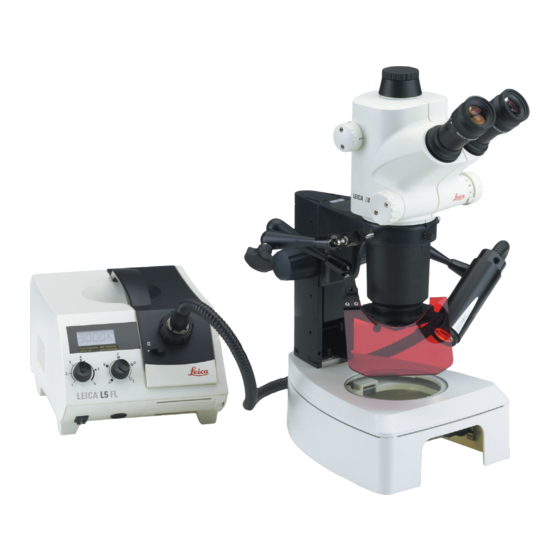
Important Information This symbol denotes additional information or explanations which promote understanding. Action Within the text, this symbol indicates actions that must be performed. Explanatory notes This symbol is found in texts next to supplementary information and explanations. Leica L5 FL... - Page 8 Leica Stereomicroscope MZ6 with Leica L5 FL Leica Stereomicroscope S8 APO with Leica L5 FL...
-
Page 9: Assembly
If other fiber-optic light guides are used: If fiber-optic light guides with guide pins are used, it must be observed that it is fitted into one of the four collet chuck slots. Leica L5 FL Fig. 5 Connected fiber-optic light guide... -
Page 10: Excitation Filter
(the position 0 through 4 are marked by means of raised points in corresponding numbers). The excitation filter is inserted in the Leica L5 FL cold-light source. To insert the filter in the filter wheel, the filter holder must be removed from the lamp. - Page 11 Fit the filter holder plate on and fasten it (Fig. 2). Insert the filter wheel in the guide and slide it into the light source until it engages (Fig. 3). Fig. 3 Inserting the filter wheel Leica L5 FL...
-
Page 12: Operation
The support arm can now be positioned. Next, turn the rotary knob clockwise Hinged arm to lock all joints. Connection of the illumination optics with holder (M and S series) Stereomicroscopes M series Connecting the arm to the column terminal (M series). Leica L5 FL... - Page 13 The left holder with the red UV protective filter is optional. Leica recommends the use of such a filter to protect the eyes of the observer. Overview of assembly M series Filter slide After assembling the illumination system, the filter-...
-
Page 14: Stereomicroscopes S Series
Allen key (1.5 mm). The left holder with the red UV protective filter is optional. Leica recommends the use of such a filter to protect the eyes of the observer (Fig. 3). Hinged arm see page 12. -
Page 15: Remote Control Connection
Connecting and disconnecting the remote control (or the tilt switch) from the light source should only be carried out when the instrument is switched off. Leica L5 FL... -
Page 16: Lamp: Installation, Replacement
The two levers must also be pressed down when the new bulb is inserted. Insert the lamp housing to the stop (you should hear it engage). Switch on the light source. Fig. 3 2 sockets for halogen lamp Leica L5 FL... -
Page 17: Starting Up
The instrument is switched off. Position: The instrument is switched on. The Leica L5 FL is equipped with a soft start to protect the halogen lamp that reduces an otherwi- se high starting current. In addition, an electronic stabilization of the lamp voltage ensures stable luminous efficiency, independent of supply voltage fluctuations. -
Page 18: Luminous Intensity Setting
Operation Luminous intensity The Leica L5 FL is equipped with two independent setting luminous intensity settings. The continuous electronic adjustment allows optimizing the lamp service life. The exact adjustment of the required brightness allows you to achieve the highest possible service life of your halogen lamp. - Page 19 After overstepping the barrier at position 5, a lamp symbol (20) appears on the LCD display that flashes for a few seconds. It serves as a maximum light indicator and indicates that the expected bulb service life is reduced compared to position 5. Leica L5 FL...
-
Page 20: Mechanical Diaphragm
Performing the illumination at the fiber-optics output with imaging or focusing optical systems results in a perfectly even illuminated area by swinging out the additional optics. Leica L5 FL... -
Page 21: Adjusting The Focusing Lens
To adjust the light spot, the screw must be untightened first. The focusing lens can now be moved back and forth. This, in turn, increases or decreases the light spot and the user can determine the size and intensity of the light spot. Leica L5 FL... -
Page 22: Maintenance
Maintenance The Leica L5 FL is maintenance-free. A disinfection of the light source for applications in the medical sector is not required and therefore, not planned. Use a soft dry cloth or commercial plastic clean- sing wipes to clean the outside of the instrument. - Page 23 "Err3" Bulb causes short circuit - Replace bulb (see p. 16) If the malfunctions listed above cannot be corrected, please consult your Leica representative. Additional repairs must be performed by an authorized Leica after-sales service. Leica L5 FL...
-
Page 24: Accessories, Spare Parts
Accessories, replacement parts A broad spectrum of accessories is available for your Leica L5 FL. Please contact your Leica representative. Only the use of original fiber-optic light guides and accessories will ensure perfect function, safety and maximum light utilization. Fiber-optic light guide Self-supporting and flexible fiber-optic light guides of different lengths and diameters as well as spot and slit illuminations are available. -
Page 25: Technical Data
Technical data Properties Values General specification Model code Leica L5 FL Dimensions (W x D x H) mm approx. 200 x 265 x 170 Weight approx. 6 Cooling axial fan Ambient temperature °C + 5 ... + 40 Relative humidity - up to 31 °C ambient temperature: 85 % - from 31 °C to 40 °C ambient temperature:... - Page 26 Leica Microsystems AG Telephone +41 71 726 33 33 Geschäftseinheit SM Fax +41 71 726 33 34 CH-9435 Heerbrugg (Switzerland) www.leica-microsystems.com www.stereomicroscopy.com...
Need help?
Do you have a question about the L5 FL and is the answer not in the manual?
Questions and answers