Table of Contents
Advertisement
Quick Links
Advertisement
Table of Contents

Related Manuals for FLIR TA72


Summary of Contents for FLIR TA72
- Page 1 USER MANUAL FLIR MODEL TA72 and TA74 UNIVERSAL FLEX CURRENT PROBE ACCESSORIES ...
-
Page 2: Table Of Contents
3.1 Key Features 4. DESCRIPTIONS 7 4.1 Meter Description 4.2 Control buttons and Indicators 5. OPERATION 9 5.1 Powering the Meter 5.2 Work Lights 5.3 AC Current Measurements 6. MAINTENANCE 13 6.1 Cleaning and Storage 6.2 Battery Replacement 7. SPECIFICATIONS 14 7.1 General specifications 7.2 AC Current Electrical specifications 8. TECHNICAL SUPPORT 16 9. WARRANTY 16 FLIR TA72_TA74 USER MANUAL Document Identifier: TA72_TA74 en‐US_AC ... -
Page 3: Disclaimers
1. Disclaimers 1.1 Copyright © 2015‐2016, FLIR Systems, Inc. All rights reserved worldwide. No parts of the software including source code may be reproduced, transmitted, transcribed or translated into any language or computer language in any form or by any means, electronic, magnetic, optical, manual or otherwise, without the prior written permission of FLIR Systems. The documentation must not, in whole or part, be copied, photocopied, reproduced, translated or transmitted to any electronic medium or machine readable form without prior consent, in writing, from FLIR Systems. Names and marks appearing on the products herein are either registered trademarks or trademarks of FLIR Systems and/or its subsidiaries. All other trademarks, trade names or company names referenced herein are used for identification only and are the property of their respective owners. 1.2 Quality Assurance The Quality Management System under which these products are developed and manufactured has been certified in accordance with the ISO 9001 standard. FLIR Systems is committed to a policy of continuous development; therefore we reserve the right to make changes and improvements on any of the products without prior notice. 1.3 Documentation To access the user manuals, extended warranty registration and notifications go to the Download tab at: http://support.flir.com. In the download area you will also find the latest releases of manuals for our other products, as well as manuals for our historical and obsolete products. The extended warranty page can also be found at www.Flir.com/testwarranty. 1.4 Disposal of Electronic Waste As with most electronic products, this equipment must be disposed of in an environmentally friendly way, and in accordance with existing regulations for electronic waste. Please contact your FLIR Systems representative for more details. FLIR TA72_TA74 USER MANUAL Document Identifier: TA72_TA74 en‐US_AC ... -
Page 4: Safety
2. Safety Safety Notes Before operating the device, you must read, understand, and follow all instructions, dangers, warnings, cautions, and notes. FLIR Systems reserves the right to discontinue models, parts or accessories, and other items, or to change specifications at any time without prior notice. Remove the batteries if the device is not used for an extended period of time. Warning Statements To ensure the safe operation and service of the meter, follow these instructions closely. Failure to observe warnings can result in severe injury. WARNINGS identify hazardous conditions and actions that could cause BODILY HARM or DEATH. Individual protective equipment should be used if HAZARDOUS LIVE parts in the installation where measurements are to be carried out could be accessible. If the equipment is used in a manner not specified by the manufacturer, the protection provided by the equipment may be impaired. Always use proper terminals, switch position, and range for measurements. To reduce the risk of fire or electric shock, do not expose this product to rain or moisture. Verify the meter operation by measuring a known current. If in doubt, have the meter serviced. Do not apply more than the rated voltage/current as marked on the meter. To avoid false readings that can lead to electric shock and injury, replace battery as soon as the low battery indicator appears. Do not use the meter in or around explosive gas or vapor. Do not use a flexible current sensor if the inner copper wire of the flexible cord is visible. ... - Page 5 CAUTIONS identify conditions and actions that could cause DAMAGE to the meter or equipment under test. Do not expose the meter to extremes in temperature or high humidity. Safety Symbols that are typically marked on meters and instructions This symbol, adjacent to another symbol, indicates the user must refer to the manual for further information. Do not apply or remove clamp from HAZARDOUS LIVE conductors Equipment protected by double or reinforced insulation Battery symbol Conforms to EU directives Do not discard this product in household trash. AC measurement Earth ground PER IEC1010 OVERVOLTAGE INSTALLATION CATEGORY OVERVOLTAGE CATEGORY I Equipment of OVERVOLTAGE CATEGORY I is equipment for connection to circuits in which measures are taken to limit the transient over‐voltages to an appropriate low level. Note – Examples include protected electronic circuits. OVERVOLTAGE CATEGORY II Equipment of OVERVOLTAGE CATEGORY II is energy‐consuming equipment to be supplied from the fixed installation. Note – Examples include household, office, and laboratory appliances. OVERVOLTAGE CATEGORY III Equipment of OVERVOLTAGE CATEGORY III is equipment in fixed installations. Note – Examples include switches in the fixed installation and some equipment for industrial use with permanent connection to the fixed installation. OVERVOLTAGE CATEGORY IV Equipment of OVERVOLTAGE CATEGORY IV is for use at the origin of the installation. Note – Examples include electricity meters and primary over‐current protection equipment FLIR TA72_TA74 USER MANUAL Document Identifier: TA72_TA74 en‐US_AC ...
-
Page 6: Introduction
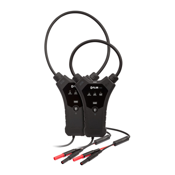
3. Introduction Thank you for choosing the FLIR TA72 or TA7 4 UNIVERSAL FLEX CURRENT PROBE ACCESSORY that can measure up to 3000A AC. A standard Digital MultiMeter (DMM) in VAC mode can be used to display the current measurement when the current probe is connected to the DMM. The TA74 is the 18” (45.7cm) clamp version and the TA72 is the 10” (25.4cm) clamp version, otherwise both meters are the same. These devices are professional CAT IV 600V CAT III 1000V instruments with high power Work Lights. This meter is shipped fully tested and calibrated and, with proper use, will provide years of reliable service. 3.1 Key Features 3000A AC Current Measurements displayed on connected DMM Convenient Flexible Clamp with locking mechanism 0.3” (7.5mm) coil diameter for measuring in tight spaces Supplied banana plug cables Power button Battery status LED indicator Current AC Range select switch 30A, 300A, 3000A Battery powered High power work lights Register for Extended Warranty www.Flir.com/testwarranty FLIR TA72_TA74 USER MANUAL Document Identifier: TA72_TA74 en‐US_AC ... -
Page 7: Descriptions
4. Descriptions 4.1 Meter Description 1. Flexible Current Clamp Coil 2. Work Lights 3. Coil tip (inserts into lock mechanism) 4. Clamp lock mechanism 5. Range indicators 6. RANGE select button 7. Power and Work Lights button 8. Test lead cable connection 9. Test leads connect to DMM Note that battery compartment is located on the back of the meter Fig. 4‐1 Description FLIR TA72_TA74 USER MANUAL Document Identifier: TA72_TA74 en‐US_AC ... -
Page 8: Control Buttons And Indicators
4.2 Control buttons and Indicators Momentary presses step through the ranges manually When powered, press to activate/deactivate work lights Press and hold to switch power ON/OFF Illuminates when the 30A ranges is selected Illuminates when the 300A ranges is selected Illuminates when the 3000A ranges is selected FLIR TA72_TA74 USER MANUAL Document Identifier: TA72_TA74 en‐US_AC ... -
Page 9: Operation
5. Operation Note: Before operating the device, please read and understand all Warning and Caution statements and follow all instructions and notes. Note: Models TA72 and TA74 are not designed for use with VFD (Variable Frequency Drive) equipment, as erroneous readings may result. Using with VFD equipment does not pose a safety hazard to personnel and will not damage equipment. Please contact FLIR for additional information. 5.1 Powering the Meter The meter is powered by two (2) AAA 1.5V batteries (located in the compartment on the back of the meter). Press and hold the Power button for > 2 seconds to switch the device ON or OFF. The meter will beep as it switches ON and one of the Range indicator lamps will be lit. Use the Range button to select a range manually. If the meter does not switch ON please check the batteries located in the rear battery compartment. Refer to the battery replacement section of this User Guide. 5.1.1 Auto Power OFF (APO) The meter switches OFF automatically after an approximately 10‐minute period of inactivity. Several seconds before the meter automatically switches OFF the meter beeps several times to alert the user. To disable the APO feature, press both the RANGE and POWER buttons simultaneously (with the meter OFF). The three range indicator LEDs will flash three times. To re‐enable APO, turn the meter OFF then ON. The meter re‐enables APO each time the meter is powered OFF. 5.2 Work Lights With the unit powered up, press the Work Light button to switch the high power Work Lights ON or OFF. Note that excessive use of the Work Lights will shorten battery life. FLIR TA72_TA74 USER MANUAL Document Identifier: TA72_TA74 en‐US_AC ... -
Page 10: Ac Current Measurements
5.3 AC Current Measurements WARNING: Ensure that power to the device under test is OFF before starting this procedure. Switch power to the device under test ON only after the clamp has been safely attached to the device under test. CAUTION: Do not move fingers above the range lamps at any time during a test. Note: Models TA72 and TA74 are not designed for use with VFD (Variable Frequency Drive) equipment, as erroneous readings may result. Using with VFD equipment does not pose a safety hazard to personnel and will not damage equipment. Please contact FLIR for additional information. Switch OFF the Clamp Adaptor, the DMM, and the device under test. Connect the Clamp Adaptor to the DMM input jacks using the supplied banana plugs (Fig. 5‐1). V AC Switch ON the DMM and set the DMM to the AC V mode. Use the RANGE button to set the measurement Fig. 5‐1 Connect to DMM range of the Clamp Adaptor to the expected current range measurement. Turn the clamp lock (1) counter‐clockwise to release the clamp (2). See Fig. 5‐2. Fully enclose the conductor under test with the flexible clamp probe (see Fig. 5‐3). Do not measure current higher than the specified current limit. Fig. 5‐2 Clamp Jaw Lock FLIR TA72_TA74 USER MANUAL Document Identifier: TA72_TA74 en‐US_AC ... - Page 11 Attach the flexible clamp coil tip (2) to the lock (1) and lock it in place by turning the clamp lock clockwise. See Fig. 5‐2. Switch the Clamp Adaptor ON (press and hold the Power button) and then switch the device under test ON. Never move fingers higher than the range indicator lights when testing. Keep hands and fingers away from the clamp coil while testing. Read the current value in the DMM display. Refer to Sections 5.3.1 to 5.3.3 for tips on determining the magnitude of current measured by the TA7x based on the DMM reading. 10. Remove power to the device under test before removing the Clamp connection. Fig. 5‐3 Clamp around one conductor 5.3.1 Manual Range Selection For the best results, with regard to output signal, select the correct range using the RANGE button, according to expected current measurement. See Table below: Range Selection Best Performance 30A (100mV/1A) 30.00A max. 300A (10mv/1A) 30.0 to 300.0 A 3000A (1mV/1A) 300.0 to 3000A FLIR TA72_TA74 USER MANUAL Document Identifier: TA72_TA74 en‐US_AC ...
- Page 12 5.3.2 DMM Reading Multiplier Table The Table below uses FLIR DM93 and CM83 DMMs as examples; However, most standard DMMs set to the AC Voltage mode will respond similarly. Note: Do not set the DMM to VFD mode when testing. DMM Displayed Readings Current Measured TA7x by TA7x FLIR DM93 FLIR CM83 Range in Amperes (A) V AC mode V AC mode Multiplier 5.0 0.500 0.50 Current = 10 x LCD 30A 15.0 1.500 1.50 reading 25.0 2.500 2.50 55.0 0.550 0.55 Current = 100 x 300A 150.0 1.500 1.50 LCD reading 250.0 ...
-
Page 13: Maintenance
6. Maintenance 6.1 Cleaning and Storage Clean the meter with a damp cloth and mild detergent; do not use abrasives or solvents. If the meter is not to be used for an extended period, remove the batteries and store them separately. 6.2 Battery Replacement CAUTION: Disconnect the meter from the conductor under test and switch the meter OFF before opening the battery compartment. Remove the battery compartment Phillips head screw from the back of the meter. Remove the battery compartment cover. Replace the 2 ‘AAA’ 1.5V batteries observing correct polarity. Re‐attach the battery compartment cover. Secure the compartment cover with the Phillips head screw. 6.2.1 Disposal of Electronic Waste As with most electronic products, this equipment must be disposed of in an environmentally friendly way, and in accordance with existing regulations for electronic waste. Please contact your FLIR Systems representative for more details. FLIR TA72_TA74 USER MANUAL Document Identifier: TA72_TA74 en‐US_AC ... -
Page 14: Specifications
7. Specifications 7.1 General specifications Clamp Jaw Flexible type with locking mechanism Coil diameter 0.3” (7.5mm); Coil tip (item 3 in Fig. 4‐1): 0.5” (13mm) Bend radius 1.5” (38mm) for TA72 and 3.1” (80mm) for TA74 Flexible Conductor length 10” (25.4 cm) for TA72 and 18” (45.7cm) for TA74 Work lights Two White LEDs AC bandwidth 45 to 500Hz (sine wave) Measurement rate 1.5 samples per second, nominal Operating Temperature 32~122F (0~50C) Operating Humidity Max 80% up to 95°F (35°C) decreasing linearly to 60% at 113°F (45°C) Storage Temperature ‐4~140F (‐20~60C) without batteries Storage Humidity 80% RH maximum Temperature Coefficient 0.2 x specified accuracy / C, < 64.5F (18C), > 82.4F (28C) Altitude Maximum operating altitude 6562’ (2000m) Battery Two “AAA” 1.5V batteries Battery life 160 hours with alkaline batteries Auto Power OFF (APO) After 10 minutes of inactivity with disable Dimensions (W x H x D) TA72: 4.7 x 11.0 x 1.0” (120 x 280 x 25 mm) ... -
Page 15: Ac Current Electrical Specifications
Output Voltage Accuracy 30.00 A AC 100mV/1A AC ± (3.0% of Full Scale) AC Current 300.0A AC 10mV/1A AC for frequency range: 45~500Hz 3000 A AC 1mV/1A AC Notes: Accuracy is given as ± (% of reading + least significant counts) at 73.4F ±9F (23C ±5C) with relative humidity lower than 80%. Accuracy is specified for a period of one year after calibration. Max. Output Voltage: 4.5V peak Output Noise: < 5mV for each range Position Error of Clamp: Accuracy and position error assumes centralized primary conductor at optimum position (center of clamp jaw), no external electrical or magnetic field, and within operating temperature range. TA72 TA72 Error TA74 TA74 Error Position* Distance 0.6” (15mm) 2.0% 1.4” (35mm) 1.0% A from optimum 1.0” (25mm) 2.5% 2.0” (50mm) 1.5% B position 1.4” (35mm) ... -
Page 16: Technical Support
8. Technical Support Main Website http://www.flir.com/test Technical Support Website http://support.flir.com Technical support Email TMSupport@flir.com Service/Repair Support Email Repair@flir.com Support Telephone number +1 855‐499‐3662 option 3 (toll‐free) 9. Warranty 9.1 FLIR Global Limited Lifetime Warranty A qualifying FLIR Test and Measurement product (the “Product”) purchased either directly from FLIR Commercial Systems Inc and affiliates (FLIR) or from an authorized FLIR distributor or reseller that Purchaser registers on‐line with FLIR is eligible for coverage under FLIR’s Limited Lifetime Warranty, subject to the terms and conditions in this document. This warranty only applies to purchases of Qualifying Products (see below) purchased and manufactured after April 1, 2013. PLEASE READ THIS DOCUMENT CAREFULLY; IT CONTAINS IMPORTANT INFORMATION ABOUT THE PRODUCTS THAT QUALIFY FOR COVERAGE UNDER THE LIMITED LIFETIME WARRANTY, PURCHASER’S OBLIGATIONS, HOW TO ACTIVATE THE WARRANTY, WARRANTY COVERAGE, AND OTHER IMPORTANT TERMS, CONDITIONS, EXCLUSIONS AND DISCLAIMERS. 1. PRODUCT REGISTRATION. To qualify for FLIR’s Limited Lifetime Warranty, Purchaser must fully register the Product directly with FLIR on‐line at http://www.flir.com within Sixty (60) DAYS of the date the Product was purchased by the first retail customer (the “Purchase Date”). Qualifying PRODUCTS THAT ARE NOT REGISTERED ON‐LINE WITHIN SIXTY (60) DAYS OF THE PURCHASE DATE WILL HAVE A LIMITED ONE YEAR WARRANTY FROM DATE OF PURCHASE. 2. QUALIFYING PRODUCTS. Upon registration, Test and Measurement products that qualify for coverage under FLIR’s Limited Lifetime Warranty are: CM7x, CM8x, DMxx, MR7x, TA7x, VP5x not including accessories which may have their own warranty. 3. WARRANTY PERIODS. For purposes of the The Limited Lifetime Warranty, Lifetime is defined as seven years (7) after the product is no longer manufactured, or ten years (10) from date of purchase, whichever is greater. This Warranty is only applicable to the original owner of the Products. Any Product that is repaired or replaced under warranty is covered under this Limited Lifetime Warranty for one hundred eighty days (180) days from the date of return shipment by FLIR or for the remaining duration of the applicable Warranty Period, whichever is longer. 4. LIMITED WARRANTY. In accordance with the terms and conditions of this Limited Lifetime Warranty, and except as excluded or disclaimed in this document, FLIR warrants, from the Purchase Date, that all fully registered Products will conform to FLIR’s published Product specifications and be free from defects in materials and workmanship during the applicable Warranty Period. PURCHASER’S SOLE AND EXCLUSIVE REMEDY UNDER THIS WARRANTY, AT FLIR’S SOLE DISCRETION, IS THE REPAIR OR REPLACEMENT OF DEFECTIVE PRODUCTS IN A MANNER, AND BY A SERVICE CENTER, AUTHORIZED BY FLIR. IF THIS REMEDY IS ADJUDICATED TO BE INSUFFICIENT, FLIR SHALL REFUND PURCHASER’S PAID PURCHASE PRICE AND HAVE NO OTHER ... - Page 17 THIS WARRANTY EXPRESSLY EXCLUDES ROUTINE PRODUCT MAINTENANCE, SOFTWARE UPDATES, AND REPLACEMENT OF MANUALS, FUSES, OR DISPOSABLE BATTERIES. FLIR FURTHER EXPRESSLY DISCLAIMS ANY WARRANTY COVERAGE WHERE THE ALLEGED NONCONFORMITY IS DUE TO NORMAL WEAR AND TEAR, OTHER ALTERATION, MODIFICATION, REPAIR, ATTEMPTED REPAIR, IMPROPER USE, IMPROPER MAINTENANCE, NEGLECT, ABUSE, IMPROPER STORAGE, FAILURE TO FOLLOW ANY PRODUCT INSTRUCTIONS, DAMAGE (WHETHER CAUSED BY ACCIDENT OR OTHERWISE), OR ANY OTHER IMPROPER CARE OR HANDING OF THE PRODUCTS CAUSED BY ANYONE OTHER THAN FLIR OR FLIR’S EXPRESSLY AUTHORIZED DESIGNEE. THIS DOCUMENT CONTAINS THE ENTIRE WARRANTY AGREEMENT BETWEEN PURCHASER AND FLIR AND SUPERSEDES ALL PRIOR WARRANTY NEGOTIATIONS, AGREEMENTS, PROMISES AND UNDERSTANDINGS BETWEEN PURCHASER AND FLIR. THIS WARRANTY MAY NOT BE ALTERED WITHOUT THE EXPRESS WRITTEN CONSENT OF FLIR. 6. WARRANTY RETURN, REPAIR AND REPLACEMENT. To be eligible for warranty repair or replacement, Purchaser must notify FLIR within thirty (30) days of discovering of any apparent defect in materials or workmanship. Before Purchaser may return a Product for warranty service or repair, Purchaser must first obtain a returned material authorization (RMA) number from FLIR. To obtain the RMA number Owner must provide an original proof of purchase. For additional information, to notify FLIR of an apparent defect in materials or workmanship, or to request an RMA number, visit http://www.flir.com. Purchaser is solely responsible for complying with all RMA instructions provided by FLIR including but not limited to adequately packaging the Product for shipment to FLIR and for all packaging and shipping costs. FLIR will pay for returning to Purchaser any Product that FLIR repairs or replaces under warranty. FLIR reserves the right to determine, in its sole discretion, whether a returned Product is covered under Warranty. If FLIR determines that any returned Product is not covered under Warranty or is otherwise excluded from Warranty coverage, FLIR may charge Purchaser a reasonable handling fee and return the Product to Purchaser, at Purchaser’s expense, or offer Purchaser the option of handling the Product as a non‐warranty return. 7. NON‐WARRANTY RETURN. Purchaser may request that FLIR evaluate and service or repair a Product not covered under warranty, which FLIR may agree to do in its sole discretion. Before Purchaser returns a Product for non‐warranty evaluation and repair, Purchaser must contact FLIR by visiting http://www.flir.com to request an evaluation and obtain an RMA. Purchaser is solely responsible for complying with all RMA instructions provided by FLIR including but not limited to adequately packaging the Product for shipment to FLIR and for all packaging and shipping costs. Upon receipt of an authorized non‐warranty return, FLIR will evaluate the Product and contact Purchaser regarding the feasibility of and the costs and fees associated with Purchaser’s request. Purchaser shall be responsible for the reasonable cost of FLIR’s evaluation, for the cost of any repairs or services authorized by Purchaser, and for the cost of repackaging and returning the Product to Purchaser. Any non‐warranty repair of a Product is warranted for one hundred eighty days (180) days from the date of return shipment by FLIR to be free from defects in materials and workmanship only, subject to all of the limitations, exclusions and disclaimers in this document. FLIR TA72_TA74 USER MANUAL Document Identifier: TA72_TA74 en‐US_AC ...
- Page 18 Corporate Headquarters FLIR Systems, Inc. 2770 SW Parkway Avenue Wilsonville, OR 97070 USA Telephone: +1 503‐498‐3547 Customer Support Technical Support Website http://support.flir.com Technical Support Email TMSupport@flir.com Service and Repair Email Repair@flir.com Customer Support Telephone +1 855‐499‐3662 option 3 (toll free) Publication Identification No.: TA72_TA74‐en‐US Release Version: AC Release Date: 2016 May Language: en‐US ...
Need help?
Do you have a question about the TA72 and is the answer not in the manual?
Questions and answers