
Related Manuals for Kontron Embedded Computers PCI - 960

Summary of Contents for Kontron Embedded Computers PCI - 960
- Page 1 PCI - 960 Board User’s Manual Version 1.02 Kontron Embedded Computers GmbH 0-0096-3989...
-
Page 3: Table Of Contents
1. Table of Contents 1. Table of Contents 1. Table of Contents ................................1 2. Introduction..................................3 2.1. Symbols used in this Manual ............................4 3. Safety Instructions ................................5 3.1. Safety Instructions for the Lithium Battery ........................5 3.2. Basic Safety and EMC Compatibility ..........................5 4. - Page 4 1. Table of Contents 11.6.1. Supervisor Password ............................71 11.6.2. User Password ..............................71 11.6.3. Boot Sector Virus Protection..........................74 11.7. Chipset ..................................75 11.7.1. North Bridge Chipset Configuration ........................75 11.7.2. South Bridge Chipset Configuration........................79 11.8. Exit ................................... 81 11.8.1.
-
Page 5: Introduction
Kontron Embedded Computers. This manual is protected by copyright. All rights are reserved by Kontron Embedded Computers. Copies of all or part of this manual or translations into a different language may only be made with the prior written consent of Kontron Embedded Computers. -
Page 6: Symbols Used In This Manual
2. Introduction 2.1. Symbols used in this Manual Symbol Meaning This symbol indicates the danger of injury to the user or the risk of damage to the product if the corresponding warning notices are not observed. This symbol indicates that the product or parts thereof may be damaged if the corresponding warning notices are not observed. -
Page 7: Safety Instructions
3. Safety Instructions 3. Safety Instructions 3.1. Safety Instructions for the Lithium Battery The PCI-960 board is equipped with a Lithium battery. For the replacing of this battery please observe the instructions described in the chapter 10.1.4.1 ”Replacing the Lithium Battery”. Caution! Danger of explosion when replaced with wrong type of battery. -
Page 8: Important Instructions
This applies to the batteries, for example. 4.3. Exclusion of Accident Liability Obligation Kontron Embedded Computers shall be exempted from the statutory accident liability obligation if the user fails to observe the safety instructions. -
Page 9: Scope Of Delivery
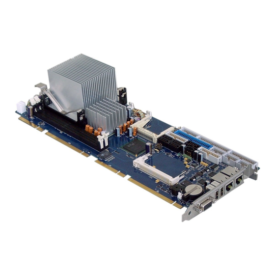
5. Scope of Delivery 5. Scope of Delivery Please check that your package is complete, and contains the items below (according to the ordered unit configuration). If you discover damaged or missing items, please contact your dealer. ❏ 1x PCI-960 Board PICMG 1.0 (full-size) Fig. -
Page 10: Board Description
6. Board Description 6. Board Description The PCI-960 is a multifunctional full-size PICMG 1.3 Slot-CPU, designed for use in highly integrated platforms for a wide range of application. Depending on the ordered configuration, the board can be equipped with an “Intel® Core™ Duo/Solo” or an ”Intel® Core 2 Duo”... -
Page 11: Features
7. Features 7. Features Form Factor: • Full size SHB PICMG 1.3 form factor (13.33 x 4.98 inch). Processor: Intel® Core™ Duo/Solo (Code name: Yonah DC/ Yonah SC), or Intel® Core 2 Duo (Code name Merom) 65 nm, • FSB of 533 or 667MHz •... - Page 12 7. Features IDE-Hard-Disk Interface • One channel with Ultra ATA100/66/33 capabilities as master and slave [40-pin, 2.54mm PC 99 compatible connectors (Pin 20 keyed, 1 IDE blue)] • The IDE interface supports PIO IDE transfers up to 16 Mbytes/sec and Ultra ATA transfers up 100 Mbytes/sec •...
- Page 13 7. Features 7.1.1.12. Multifunction Connector • One hard drive activity LED for all IDE devices • Power LED • Keyboard & Mouse • Reset switch 7.1.1.13. Connector for Power Buttons • 2-pin connector for additional power button Power Button Control: If an ATX power supply is used, the SBC can control it either through: ❏...
- Page 14 7. Features 7.1.1.18. Real Time Clock (RTC) Motorola MC146818B-compatible RTC with 256 bytes of battery-backed RAM • RTC supports a date alarm that allows for scheduling a wake-up event up to 30 days in advance • A coin-cell battery (CR2032) powers the real-time clock and CMOS memory •...
-
Page 15: Functional Diagram
8. Functional Diagram 8. Functional Diagram Intel Core Duo / Solo Core 2 Duo 1x PCIe x16 533/667 MHz DDR2 SDRAM DIMM Memory LAN1 LAN2 Intel Controller DDR2 SDRAM DIMM 1Gbps 1Gbps 945GM 1x VGA PCIe x16 1x TV-Out Controller Controller Graphics Controller... -
Page 16: Jumpers And Connectors Overview
9. Jumpers and Connectors Overview 9. Jumpers and Connectors Overview The jumpers and connectors of the PCI-960 board will be described in detail below. Signals suffixed by a pound (#) are active-low. All headers will have a pitch of 0.100“ (2.54mm), otherwise noted different. Connectors on the I/O Panel VGA Connector LAN1 Connector... - Page 17 9. Jumpers and Connectors Overview PCI-960 – User’s Manual (V1.02)
-
Page 18: Connectors Located On Slot Bracket
9. Jumpers and Connectors Overview 9.1.1. Connectors located on Slot Bracket 2x USB LAN2 LAN1 Fig. 4: PCI-960 – I/O panel connectors 9.1.1.1. J36: VGA Connector An external (analog) monitor can be plugged into this interface which is provided as a 15-pin D-SUB socket. Signal Name 15-pin D-SUB Socket (female) Analog red output... - Page 19 9. Jumpers and Connectors Overview 9.1.1.3. J28 and J29: USB Connectors The PCI-960 board provides two external USB 2.0/1.1 interfaces. These connectors allow to connect USB-compatible devices to the PCI-960 Slot-CPU. Pin Signal Name 4-pin USB Socket Type A Version 2.0/1.1 VCC, fused Data- Data+...
-
Page 20: Jumpers On The Pci-960
9. Jumpers and Connectors Overview 9.1.2. Jumpers on the PCI-960 The jumpers on the PCI-960 allow you to configure your CPU card according to the needs of your applications. In order to change a jumper setting, turn off the computer by use of the ATX-power supply switch. If your power supply has no On/Off switch, disconnect the main power source. - Page 21 9. Jumpers and Connectors Overview 9.1.2.3. JP5: Disable CMOS Backup Restore Function This jumper prevents the use of CMOS backup (in the case that the CMOS data are invalid). Set jumper (JP5) prevents, that wrong settings of the backup are loading. The system boots using the “power on defaults” from onboard RAM. In order to change a jumper setting, please turn off the computer and unplug the power source to the board.
-
Page 22: Connectors On-Board
9. Jumpers and Connectors Overview 9.1.3. Connectors On-Board 9.1.3.1. J32: +12V ATX Power Connector The ATX connector is used to connect the +12V ATX power supply to the board in order to provide power to the CPU. J32: 4-pin Connector Signal Name +12V +12V... - Page 23 9. Jumpers and Connectors Overview Speaker:-pins 7 and 8 These-pins provide an interface to connect a speaker for audio tone generation. An 8-ohm speaker is recommended. Keyboard:-pins 1, 2, 3, and 5 These-pins can be used to connect the cable connection for an external PS/2 keyboard connector.
- Page 24 9. Jumpers and Connectors Overview 9.1.3.6. J34: Additional Power Button Connector This connection allows you to attach an external ATX power button. J34: 2-pin Row Pin # Signal Name 9.1.3.7. J8: Primary IDE Connector Signal Name Pin # J8: Box Header, Pin # Signal Name (shrouded), DIP 40-pin...
- Page 25 9. Jumpers and Connectors Overview 9.1.3.9. J12: CompactFlash Connector The CompactFlash™ connector is located on the top side of the PCI-960 board. Signal Pin # Pin # Signal J12: CF Socket Name Name AMP 1470103-1 NC/CD1 CS1# CS3# GND (ATA#) IOR# IOW# +5V (WE#)
- Page 26 9. Jumpers and Connectors Overview 9.1.3.10. J7: Parallel Port Connector (LPT) LPT is an IEEE1284 compatible interface and supports Normal/EPP/ECP mode. This port is provided as a 26-pin boxed header. Signal Name Pin # J7: Boxed Header, Pin # Signal Name DIP 26-pin Strobe# AutoFeed#...
- Page 27 9. Jumpers and Connectors Overview 9.1.3.11. J2: LVDS (JILI) Connector The LVDS (JILI) connector complies with JILI Specification 2.0. This connector allows you to connect LVDS-compatible receivers. For the different required cable kits, please contact our GSS support. J2: LVDS (JILI) Connector Pin # Signal Name ODD_LVD0-...
- Page 28 9. Jumpers and Connectors Overview 9.1.3.12. J6: Floppy Disk Connector The Floppy disk connector supports up to two floppy disk drives: 5.25” (360KB and 1.2MB) and/or 3.5” (720KB, 1.44MB, and 2.88MB). J6: Boxed Header, Signal Name Pin # Pin # Signal Name DIP 34-pin Densel0#...
- Page 29 9. Jumpers and Connectors Overview 9.1.3.14. J10: Serial Port Connector COM1 The 10 -pin boxed header is to be used with the supplied serial cable. COM1 pin assignment RS232: J10: Boxed Header, RS232 D-SUB DIP 10-pin (Pinning on the on-board header) Connector Pin # Signal Name...
- Page 30 9. Jumpers and Connectors Overview 9.1.3.15. J11: Serial Port Connector COM2 The 10-pin box header is to be used with the supplied serial cable. This interface is RS232 (default) and can be configured as RS422 or RS485 (BIOS Setup). For RS422 and RS485 mode, please install the jumper caps (JP7 and JP8) to use the onboard termination resistors (120ohm).
- Page 31 9. Jumpers and Connectors Overview COM2 pin assignment as RS485: J11: Boxed Header, D-SUB RS485 DIP 10-pin Connector (Pinning on the on-board header) Pin # Signal Name Pining on the supplied cable connector: TRxD–, Transmit/Receive data TRxD+, TRxD– Transmit/Receive data TRxD+ 12 V, fused COM2...
- Page 32 9. Jumpers and Connectors Overview 9.1.3.18. J24: PS/2 Keyboard-Lock Connector The keyboard lock allows the user to lock the PS/2 keyboard (if the chassis is equipped with a keyboard lock), protecting the system from unauthorized use. J24:Pin-Row: 2-pin Pin # Signal Name KB Lock 9.1.3.19.
- Page 33 9. Jumpers and Connectors Overview 9.1.3.22. J21: SPDIF-In & -Out The SPDIF connector (J21) allows digital audio input and output via an adapter cable with slot mounting bracket for coaxial and/or optical fiber connection (not included). J21: Pin-Row: 5-pin Pin # Signal Name SPDIF-out SPDIF-in...
- Page 34 9. Jumpers and Connectors Overview 9.1.3.25. J26: MiniPCI Connector J26: MiniPCI Slot, 124-pin, Pin Assignments Signal Signal Signal AD21 AD22 AD19 AC97_SYNC AD20 GND (M66EN) AC97_SDATAIN AC97_SDATAOUT AD17 AC97_BITCLK AD18 GND (ACCID0) -CEB2 PU (ACCID1) AD16 AC97_RESET -IRDY MPCI_AUDMON VCC3 -FRAME -CLKRUN MPCI_AUDOUT...
-
Page 35: Picmg 1.3 Connector (Edge Connector) Pci Express And Pci(-X) Interfaces
9. Jumpers and Connectors Overview 9.1.4. PICMG 1.3 Connector (Edge Connector) PCI Express and PCI(-X) Interfaces The “Side A” pins are on component side, the “Side B” pins are on solder side. 9.1.4.1. SHB Express Connector Pinout x16 PCIe Connector A x8 PCIe Connector B Side B Side A... - Page 36 9. Jumpers and Connectors Overview a_PETp3 a_PETn3 a_PERp3 a_PERn3 a_PETp4 a_PETn4 a_PERp4 a_PERn4 a_PETp5 a_PETn5 a_PERp5 a_PERn5 a_PETp6 a_PETn6 a_PERp6 a_PERn6 a_PETp7 a_PETn7 a_PERp7 a_PERn7 RSVD NC* +3.3V +3.3V +3.3V +3.3V +3.3V +3.3V +3.3V +3.3V +3.3Vaux NC* +3.3Vaux NC* PCI-960 – User’s Manual (V1.02)
- Page 37 9. Jumpers and Connectors Overview x16 PCIe Connector C x8 PCIe Connector D Side B Side A Side B Side A USB0P INTB# INTA# USBON INTD# INTC# USB1P USB1N REQ3# GNT3# USB2P REQ2# GNT2# USB2N PCI_RST# GNT1# USB3P REQ1# GNT0# USB3n REQ0# SERR#...
- Page 38 9. Jumpers and Connectors Overview +12V +12V +12V +12V +12V +12V +12V +12V +12V +12V +12V +12V +12V +12V +12V +12V +12V +12V +12V +12V NC*: Not Connected PCI-960 – User’s Manual (V1.02)
-
Page 39: Peripherals
10. Peripherals 10. Peripherals 10.1.1. Temperature Sensors The CPU temperature sensor is integrated in the CPU. It provides the most relevant CPU temperature readings and monitors the CPU temperature to make sure that the system is operating at a safe temperature level. The chassis temperature sensors are available on-board as thermal diodes to measure the on-board environmental temperatures. -
Page 40: Lithium Battery
10. Peripherals 10.1.4. Lithium Battery PCI-960 is provided with a 3.0 V “coin cell” lithium battery for the RTC operation and CMOS Setup RAM. Please observe the chapter 3.1 “Safety Instructions for the Lithium Battery”. Battery socket Lithium battery Spring Fig. -
Page 41: Ami Bios Configuration
11. AMI BIOS Configuration 11. AMI BIOS Configuration This chapter describes the settings available in the optional AMI BIOS for the PCI-960 board. The AMI BIOS (Basic Input/Output System) pre- installed in your computer system’s ROM supports Intel® Core™ 2 Duo and Intel® Core™ Solo (Mobile) processors in a standard IBM AT compatible I/O system. 11.1. -
Page 42: Main
11. AMI BIOS Configuration 11.2. Main 11.2.1. System Time / System Date System Time This field indicates the time of the device. If you change the time setting, enter the time in the format HH:MM:SS HH=Hours MM=Minutes SS=Seconds System Date This field indicates the date of the device. - Page 43 11. AMI BIOS Configuration Board Information PCI-960 – User’s Manual (V1.02)
-
Page 44: Advanced
11. AMI BIOS Configuration 11.3. Advanced You can select the sub menus of the Advanced BIOS Setup: • CPU Configuration • IDE Configuration • Floppy Configuration • SuperIO Configuration • Hardware Health Configuration • ACPI Configuration • Event Log Configuration •... -
Page 45: Cpu Configuration (Configure Advanced Cpu Settings)
11. AMI BIOS Configuration 11.3.1. CPU Configuration (Configure advanced CPU settings) 11.3.1.1. Max CPUID Value Limit Disabled for Windows XP Available settings are: Disabled and Enabled . 11.3.1.2. Execute Disable Bit When “ Disabled ” is set, forces the Execute-Disable Bit Capability extended feature bit to always return 0. Available settings are: Enabled and Disabled . -
Page 46: Ide Configuration
11. AMI BIOS Configuration 11.3.2. IDE Configuration This field can be use to select options for the IDE Configuration settings. 11.3.2.1. ATA/IDE Configuration Available settings are: Enhanced, Compatible and Disabled . 11.3.2.2. Configure SATA as Available settings are: IDE, RAID and AHCI. 11.3.2.3. - Page 47 11. AMI BIOS Configuration 11.3.2.5. IDE Detect Time Out (Sec) Set this option to stop the AMI BIOS from searching for IDE devices within the specified number of seconds. Basically, this allows you to fine-tune the settings to allow for faster boot times. Low settings can cause unreliable detection! Possible settings are: 0, 5, 10, 15, 20, 25, 30 and 35.
- Page 48 11. AMI BIOS Configuration Primary IDE Master / Primary IDE Slave These fields call the submenu to make corresponding settings of the IDE devices. You should change the default settings only if you are connecting an additional IDE drive (e.g. Hard disk drive).
- Page 49 11. AMI BIOS Configuration 11.3.2.7. Type Select the type of device connected to the system. Not Installed, Auto , CD/DVD and ARMD (ATAPI Removable Media Device) . 11.3.2.8. LBA/Large Mode The LBA ( L ogical B lock A ddressing)/Large Mode option allows you to enable or disable support for IDE devices with capacities greater than 528MB.
- Page 50 11. AMI BIOS Configuration 11.3.2.10. PIO Mode These fields allow your system IDE controller to work faster. Rather than have the BIOS issue a series of commands that transfer to or from the IDE drive, PIO (Programmed Input/Output) allows the BIOS to communicate with the controller and CPU directly.
-
Page 51: Floppy Configuration
11. AMI BIOS Configuration 11.3.2.12. S.M.A.R.T. S. M. A. R. T. (Self-Monitoring, Analysis and Reporting Technology) is used to predict drive failures. (The integrated drive has to support this feature). Available Settings are: Auto , Disabled and Enabled . 11.3.2.13. 32Bit Data Transfer This option allows you to enable or disable the 32bit data transfer rate for the IDE devices. -
Page 52: Super Io Configuration
11. AMI BIOS Configuration 11.3.4. Super IO Configuration This field can be used to select the Super I/O settings. 11.3.4.1. Onboard Floppy Controller This function enables or disables the floppy drive controller. Possible settings are: Disabled and Enabled. Disabled If a supplementary floppy disk controller is used or the system is not equipped with a floppy disk drive. Enabled The floppy disk controller of the board is used. - Page 53 11. AMI BIOS Configuration 11.3.4.4. Serial Port2 Mode This field allows you to select the line mode for serial communication. Available settings are: Normal (RS232) , RS422 and RS485 . If the [Serial Port2 Mode] is set to RS422 is available a supplementary option: [Serial Port2 Transmitter] If Serial Port2 Mode is set to RS422 Available settings...
- Page 54 11. AMI BIOS Configuration 11.3.4.6. Parallel Port Mode This field is used to specify whether the parallel port is to be used as a bi-directional input/output port or just as an output port. ECP and EPP transfer modes allow faster transfer rates of 2 and 2.4 Mbytes/s. These modes will only work with peripheral devices which support them.
-
Page 55: Hardware Health Configuration
11. AMI BIOS Configuration 11.3.5. Hardware Health Configuration 11.3.5.1. H/W Health Function This option allows you to enable or disable the Hardware Health Event Monitoring. Available settings are: Enabled and Disabled . 11.3.5.2. Hardware Health Event Monitoring These fields allow you to observe the parameters of the hardware monitoring function feature of the system. The values are read-only values for the monitoring of the system and show the PC health status. -
Page 56: Acpi Configuration
11. AMI BIOS Configuration 11.3.6. ACPI Configuration ACPI Configuration settings allow you to select the Advanced Power Management (APM) options. General ACPI Configuration 11.3.6.1. Suspend Mode This option allows you to select the ACPI state used for System Suspend. It is possible to choose between: Auto, S1 (POS) and S3 (STR). S1 (POS) Power On Suspend: The system appears off. - Page 57 11. AMI BIOS Configuration Advanced ACPI Configuration 11.3.6.3. ACPI Versions Features This option allows you to set the corresponding ACPI version. It is possible to choose between: ACPI v1.0, ACPI v2.0 and ACPI v3.0. 11.3.6.4. ACPI APIC support This option determines whether or not to include the ACPI APIC table pointer to the RSDT pointer list. It is possible to choose between: Enabled and Disabled.
- Page 58 11. AMI BIOS Configuration 11.3.6.7. AMI OEMB table This option allows you to include the OEMB table pointer to R(X)SDT pointer list. It is possible to choose between : Enabled and Disabled . Enabled This setting enables adding an OEMB table. Disabled This setting disables adding an OEMB table.
-
Page 59: Event Log Configuration (Event Logging Details)
11. AMI BIOS Configuration 11.3.7. Event Log Configuration (Event Logging details) AMI BIOS logs certain events to be event log, which can be configured using these options. 11.3.7.1. View Event Log This selection allows you to view the event log. 11.3.7.2. -
Page 60: Pci Express Configuration
11. AMI BIOS Configuration 11.3.9. PCI Express Configuration 11.3.9.1. Active State Power Management This option allows you to enable or disable the L0s and L1 link power states. Available settings are: Enabled and Disabled . PCI-960 – User’s Manual (V1.02) -
Page 61: Remote Access Configuration (Configure Remote Access Type And Parameters)
11. AMI BIOS Configuration 11.3.10. Remote Access Configuration (Configure Remote Access type and parameters) 11.3.10.1. Remote Access This option allows you to enable or disable the console redirection features. Available settings are: Enabled and Disabled . If this option is set to “ Enabled ” are available following options: 11.3.10.2. - Page 62 11. AMI BIOS Configuration 11.3.10.4. Flow Control Flow Control lets computers (host and client) tell each other when they can accept more data for transmission and when to wait. This handshaking prevents data from being lost because one computer was busy. The available settings are: None, Hardware and Software .
-
Page 63: Trusted Computing
11. AMI BIOS Configuration 11.3.11. Trusted Computing This option allows you to enable or disable the TPM TCG (TPM 1.1/1.2) support in BIOS. Available settings are: Yes and No . If this option is set to “Yes” is available following options: [Execute TPM Command]. 11.3.11.1. -
Page 64: Usb Configuration
11. AMI BIOS Configuration 11.3.12. USB Configuration This field allows you to select options for USB configuration. 11.3.12.1. Legacy USB Support This function enables or disables support for legacy USB. Enabling legacy USB support allows using USB devices under DOS and other non-Plug & Play operating systems. Possible settings are: Enabled, Disabled and Auto. - Page 65 11. AMI BIOS Configuration USB Mass Storage Device Configuration 11.3.12.5. USB Mass Storage Reset Delay This option specifies amount of time the BIOS USB code should wait after issuing a reset to the USB mass storage devices (only needed for slow starting devices). It is possible to choose between: 10 Sec, 20 Sec, 30 Sec, and 40 Sec.
-
Page 66: Pcipnp
11. AMI BIOS Configuration 11.4. PCIPnP The “PCI PnP Configuration” section of the BIOS controls the settings for the onboard PCI slots. 11.4.1.1. Clear NVRAM This Option allows you to clear the NVRAM during the system boot. The available settings are: No and Yes . 11.4.1.2. - Page 67 11. AMI BIOS Configuration 11.4.1.3. PCI Latency Timer This choice specifies, how long (PCI clock) a PCI card can still use the PCI Bus as master, if another PCI card requests the access to the PCI Bus. The available settings are: 32, 64, 96, 128, 160, 192, 224 and 248. 11.4.1.4.
- Page 68 11. AMI BIOS Configuration 11.4.1.10. Reserved Memory Size This option allows you to specify the memory size for the ISA extension cards (only to be used if the ISA-Bridge is equipped on the backplane). Available settings are: 16k, 32k, 64k and Disabled . If this option is enabled to 16k, 32k or 64k a supplementary option is available: “...
-
Page 69: Boot
11. AMI BIOS Configuration 11.5. Boot In the Boot menu you define the sequence in which the system BIOS searches the drives for system files to start the operating system. Boot Settings Configuration PCI-960 – User’s Manual (V1.02) - Page 70 11. AMI BIOS Configuration 11.5.1.1. Quick Boot This option allows or restricts the BIOS to perform all POST tests. It is possible to choose between: Enabled and Disabled. Enabled This setting allows the BIOS to skip certain POST tests to boot faster. Disabled This setting allows the BIOS to perform all POST tests.
- Page 71 11. AMI BIOS Configuration 11.5.1.6. Wait For ‘F1’ If Error This option specifies if errors detected during the boot time, determine the interruption of the boot procedure. It is possible to choose between: Enabled and Disabled. Enabled The boot procedure is stopped, whenever the BIOS detect an error. The system waits for a user input.
- Page 72 11. AMI BIOS Configuration Boot Device Priority In the Boot Device Priority menu you define the sequence in which the system BIOS searches the drives for system files to start the operating system. List of devices available for use as boot devices: ( the possible selection is depending on the system configuration ). 11.5.1.10.
-
Page 73: Security
11. AMI BIOS Configuration 11.6. Security PCI-960 supports Supervisor and User password. Valid password (Supervisor and User) can be a 1 to 6 alphanumeric characters combination. If you are using both passwords the Supervisor password must be set first. Keep a record of the new password when the password is changed. If you forget the password, you must erase the system configuration information in NVRAM. - Page 74 11. AMI BIOS Configuration 11.6.2.1. Change Supervisor Password Select this option and press <Enter> to access the sub menu. You can use the sub menu to change the supervisor password. Select the “Change Supervisor Password” option from the Security Setup menu and press <Enter>. “Enter New Password:”...
- Page 75 11. AMI BIOS Configuration If a Supervisor Password is installed two options are available: “User Access Level” with following settings: Full Access, Limited, View Only, and No Access. “Password Check” with following settings: Setup and Always . 11.6.2.2. Change User Password Select this option and press <Enter>...
-
Page 76: Boot Sector Virus Protection
11. AMI BIOS Configuration 11.6.3. Boot Sector Virus Protection With this field you can protect the boot sector against virus. It is possible to choose between: Enabled and Disabled. The boot sector cannot be changed. A virus that attacks the boot sector cannot infect the system. Select “... -
Page 77: Chipset
11. AMI BIOS Configuration 11.7. Chipset All “Chipset” BIOS Setup options are described in this section. The “Chipset” BIOS Setup screen is shown below. 11.7.1. North Bridge Chipset Configuration You can use this field to select options for the NorthBridge chipset configuration. PCI-960 –... - Page 78 11. AMI BIOS Configuration 11.7.1.1. DRAM Frequency The available settings are: The available settings are: Auto, 400 MHz,-533MHz and 667 MHz . 11.7.1.2. Configure DRAM Timing by SPD The available settings are: Enabled and Disabled . 11.7.1.3. Memory Hole In order to improve performance, certain space in memory can be reserved for ISA cards. This memory must be mapped into the memory space 15MB-16MB.
- Page 79 11. AMI BIOS Configuration Video Function Configuration 11.7.1.9. DVMT Mode Select This option allows you to select the DVMT operating mode. Available settings are: Fixed Mode, DVMT Mode and Combo Mode . 11.7.1.10. DVMT/Fixed Memory Available settings are: Maximum DVTM , 64MB and 128MB . The option [ DVMT/Fixed Memory ] is not accessible when the option [ DVMT Mode Select ] is set to Combo Mode .
- Page 80 11. AMI BIOS Configuration 11.7.1.14. TV Connector This option allows you to select the used TV output connector. Available settings are: Auto, Composite, Component, Composite & RGB, S-Video, SCART Composite, Scart Compos. & RGB, Scart Compos &s-Vdo and SMPTE253 Compon. RGB. 11.7.1.15.
-
Page 81: South Bridge Chipset Configuration
11. AMI BIOS Configuration 11.7.2. South Bridge Chipset Configuration You can use this field to select options for the SouthBridge chipset configuration. 11.7.2.1. USB Function This option allows you to enable or disable the host controllers. Possible settings are: Disabled, 2 USB Ports, 4 USB Ports, 6 USB Ports and 8 USB Ports . - Page 82 11. AMI BIOS Configuration 11.7.2.5. 1. / 2. / 3. Ethernet Controller These options allow you to enable or to disable the corresponding Ethernet controller. Possible settings are: Enabled and Disabled . 11.7.2.6. SLP_S4# Min Assertion Width The available settings are: 1 to 2 seconds , 2 to 3 seconds , 3 to 4 seconds and 4 to 5 seconds.
-
Page 83: Exit
11. AMI BIOS Configuration 11.8. Exit 11.8.1. Save Changes and Exit This field saves the settings you have made and exits BIOS Setup. 11.8.2. Discard Changes and Exit This field exits BIOS Setup without saving the new settings. 11.8.3. Discard Changes This field resets all values to those that were active when the computer was turned on without exiting BIOS Setup. -
Page 84: Technical Data
12. Technical Data 12. Technical Data PCI-960 Board Main Specifications Processor Intel® Core™ 2 Duo and Intel® Core™ Solo (Mobile), Socket 478 (Mobile) For CPU frequency, please refer to the actually data sheet on the web page: www.kontron.com Board Type PICMG 1.3 standard, full size 2x 240-pin DDR2 DIMMs Memory Socket... -
Page 85: Electrical Specifications
12. Technical Data Onboard 1x Hardware Monitor supports monitoring of: Connectors 2x Fan-Speed (1xCPU and 1x system) Power Button Chassis Intruder 3x SMBus user defined GPIO[0-7] 3x 12V Fan Power 1x 12V ATX Power 1x Additional Power Button 1x Suspend-LED 1x Keyboard&Mouse 1x Keyboard Lock 1x LPC-Bus (reserved) -
Page 86: Technical Support
Be ready to explain the nature of your problem to the service technician. If you have any questions about Kontron Embedded Computers or our products and services, you may reach us at the aforementioned numbers, or at: www.kontron.com...
Need help?
Do you have a question about the PCI - 960 and is the answer not in the manual?
Questions and answers