Table of Contents
Advertisement
Quick Links
High Voltage Power Supply
SAFETY AND INSTALLATION
Issue
Date
Issuing Authority
Checked
Approved
XMPG10P10/24
INSTRUCTIONS
Document Number: 81233-4.
A
23/01/18
I-5650
E-mail :
Broomers Park, Broomers Hill Lane
Pulborough, W. Sussex, RH20 2RY
1
16/04/2021
10465C
Tel: +44 (0)1798 873986
Fax: +44 (0)1798 872479
hvsales@spellmanhv.co.uk
Advertisement
Table of Contents

Related Manuals for Spellman XMPG10P10


Summary of Contents for Spellman XMPG10P10
- Page 1 Tel: +44 (0)1798 873986 Fax: +44 (0)1798 872479 E-mail : hvsales@spellmanhv.co.uk Broomers Park, Broomers Hill Lane Pulborough, W. Sussex, RH20 2RY High Voltage Power Supply XMPG10P10/24 SAFETY AND INSTALLATION INSTRUCTIONS Document Number: 81233-4. Issue Date 23/01/18 16/04/2021 Issuing Authority I-5650...
- Page 2 SAFETY DANGER HIGH VOLTAGE RISK OF ELECTROCUTION Observe extreme caution when working with this equipment High voltage power supplies must always be connected to protective earth Do not touch connections unless equipment is turned off and the capacitance of both the load and power supply are grounded Allow adequate time for discharge of internal capacitance of the power supply...
-
Page 3: Table Of Contents
Change History Section Reason for Change Issue Original Added regulatory specifications Added environmental conditions Added mechanical Added input and output connections details Added setup and adjustments Contents Unit Description ............................4 Safety ................................. 4 Regulatory Specifications ........................4 Environmental conditions ........................5 Mechanical .............................. -
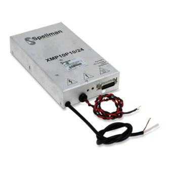
Page 4: Unit Description
Unit Description The XMPF10N5/24 unit consists of one chassis containing the high voltage power supply. The dimensions are 185mm x 105mm x 33.5mm The unit is designed for operation from 24Vdc ± 10%. The maximum rated input current is 2A. The unit provides an HV Cathode output rated at 10kV, 10W. -
Page 5: Environmental Conditions
Environmental conditions Operating Protection: The power supply will be designed to meet IP40 and will be reasonably protected against dust. Temperature: +5C to +40C. Relative Humidity: 20% to 80% (no condensation) Storage Temperature: -40C to +70C. Relative humidity: 5% to 95% Absolute humidity: maximum 25 gm ³... -
Page 6: Installation
Initial Inspection Inspect the package exterior for evidence of damage due to handling in transit. Notify the carrier and Spellman immediately if damage is evident. Do not destroy or remove any of the packing material used in a damaged shipment. -
Page 7: Input And Output Connections
Input and Output Connections Monitoring and Control 7.1.1 HV enable This is a digital input which controls the HV output. Driving this input low (< 0.8V) will cause the HV output to be enabled and ramp up to its programmed value. The filament current will start to ramp up after the high voltage has reached its programmed value, approximately 3 seconds after the HV output is enabled. - Page 8 Pin connections The low voltage signal connections are made by a 15 way ‘D’ connector; the pin out is shown below: Pin # Signal Name Range +24V input Power Ground Preheat (set value) 0 – 5V from internal pre set Test (Filament Current Direct Program) Do not connect HV enable...
-
Page 9: Set Up & Adjustments
Set Up & Adjustments Connect 24V power to the unit, +24V (pin 1), 0V (pin 2), do not Enable the unit. Connect a multi-meter to pin 15 with return to pin 14. Turn Filament Current Limit adjustment potentiometer on the case side to set a safe value for the maximum filament current.
Need help?
Do you have a question about the XMPG10P10 and is the answer not in the manual?
Questions and answers