
Related Manuals for DYNACO PAT-4


Summary of Contents for DYNACO PAT-4
- Page 1 PAT-4 POWER SUPPLY ASSEMBLY MANUAL Rev B Version © 2014-2019 AkitikA, LLC All rights reserved Revision Bp05 December 18, 2019 Page 1 of 16...
-
Page 2: Table Of Contents
Figure 3-Showing wires to cut and screws to remove ............12 Figure 4-Mounting the power supply to the PAT-4............13 Figure 5-New Power Supply Installed in PAT-4 (this PAT-4 has tone control defeat switch) ..........................14 Figure 6-Schematic of PAT-4 Electronically Regulated Power Supply (Rev B) ..... 15 Figure 7-demonstrating the resistor color code .............. -
Page 3: Section 1: About This Manual
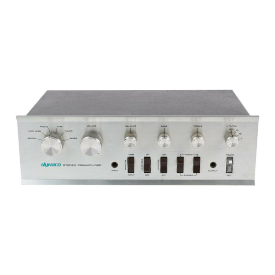
This manual gives the information you need to build and install a replacement power supply in the Dynaco PAT-4 Preamp. Compared to the original power supply, the replacement power supply should give better sound. That’s because the outputs are electronically regulated. -
Page 4: Tools You'll Need
2. use simple hand tools like screwdrivers, wire cutters, and pliers. 3. read and follow directions. It helps if you: 1. know a bit about electronics, or 2. have a friend who knows a bit about electronics 3. can get to YouTube to watch a few helpful videos about the assembly process (not available as of this version of the manual) Tools You’ll Need You’ll need the following tools:... -
Page 5: Section 2: Building The Power Supply Pc Board
Section 2: Building the Power Supply PC Board First, Get A Soup Bowl! A wide, flat soup bowl makes a great holder for the parts that you’ll install into the printed circuit board. So get that soup bowl, then open the parts envelope, and carefully transfer the parts into the soup bowl. -
Page 6: Figure 1-Component Locating Guide
Figure 1-Component Locating Guide Page 6 of 16... -
Page 7: Resistor Notes
Designation Value Color Code Done() Brown, Black, Black, Black, Brown Brown, Black, Black, Black, Brown Brown, Black, Black, Black, Brown Brown, Black, Black, Black, Brown Brown, Black, Black, Red, Brown Brown, Black, Black, Red, Brown Brown, Black, Black, Red, Brown Brown, Black, Black, Red, Brown Brown, Black, Black, Red, Brown 3240... -
Page 8: Install The Diodes
Install the Diodes Be careful! Diodes have a polarity. Make sure the band on the diode aligns with the banded end of the silk screen! Designation Value Marking, type Done() 1N4004 4004, 400 PIV 1 Amp 1N4004 4004 1N4004 4004 1N4004 4004 1N4004... -
Page 9: Install The To-92 Package Integrated Circuits
Designation Type Description Done? () 2N5551, TO-92 150 V NPN bipolar transistor 2N5551, TO-92 150 V NPN bipolar transistor 2N5401, TO-92 150 V PNP bipolar transistor 2N5401, TO-92 150 V PNP bipolar transistor Don’t use too much solder on the transistor leads. This is one place where the spacing is close enough that extra solder might cause short circuit between two leads on a given transistor. -
Page 10: Install The Capacitors
Orient the transistors so the position of the metal tab matches the silk-screen outline. Solder the outside leads first and assure that the transistors are straight, then solder the center lead. Let the shoulders of the transistors leads set their height above the board Designation Type Description Done? () -
Page 11: Remove The Old Power Supply
Remove the Old Power Supply 1. Disconnect the PAT-4 from your music system. 2. Unplug the power cord and allow the preamp to sit for one minute before moving Caution: Be sure that the preamp power is unplugged! 120 VAC can be lethal! 240 VAC can be lethal! 3. -
Page 12: Figure 3-Showing Wires To Cut And Screws To Remove
Figure 3-Showing wires to cut and screws to remove Page 12 of 16... -
Page 13: Install The New Power Supply
32x1/4” sems screws (sems screws have the captive lock washer). Make sure that they’re both straight and tight. Figure 4-Mounting the power supply to the PAT-4 2. Use the old mounting holes from C29 to fasten the brackets to the chassis. Figure 5, on the next page, may also clarify this bit of the assembly. -
Page 14: Final Test And Assembly
3. Put the top back on, and re-install the four screws that hold it in place. 4. Reinstall the PAT-4 to your music system. The PAT-4 doesn’t use negative 17.5 volts, yet! There should be no wires connected to either N17P5 or its associated grounds. -
Page 15: Schematic
Schematic Figure 6-Schematic of PAT-4 Electronically Regulated Power Supply (Rev B) Note: Schematic in RevBP03 of manual showed R3=20K, but it has always been R3=10K Page 15 of 16... -
Page 16: Resistor Color Code
Resistor Color Code Figure 7-demonstrating the resistor color code Here’s an extreme close-up of a ¼ W metal film 20K (20,000) Ohm resistor, designated by the standard resistor color code. The colors map to numbers: Color Number Black Brown Orange Yellow Green Blue...
Need help?
Do you have a question about the PAT-4 and is the answer not in the manual?
Questions and answers