DYNACO Stereo 70 Restoration Manual
Hide thumbs
Also See for Stereo 70:
- Restoration manual (20 pages) ,
- Owner's manual (12 pages) ,
- Instructions for assembly (16 pages)
Advertisement
Table of Contents
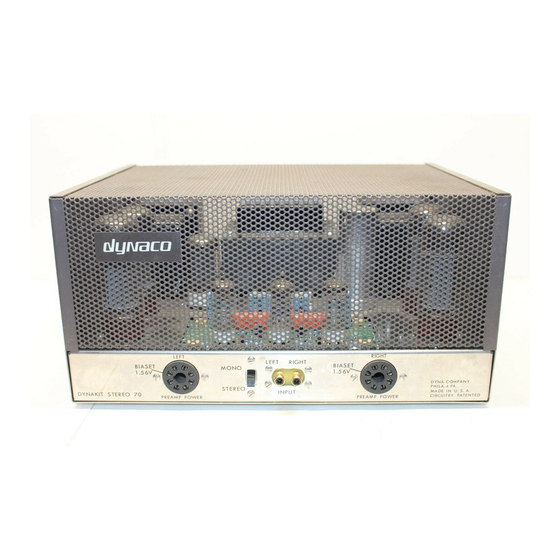
Dynaco Stereo 70 Power Amplifier
Restoration Manual
Addendums
Page 1
R0 4-03
Addendum 1 Testing the Dynaco Stereo-70 Transformers
A. Power Transformer
1. Remove all tubes (4X output tubes, 2X driver tubes, 1x GZ-34 rectifier tube)
2. Disconnect the Red/Black Stripe wire connected to the Selenium rectifier – cover this
end with tape or 1/8" shrink tubing to prevent contact with other items
3. Install a 0.1A fuse
4. Connect the amplifier to 120VAC mains.
5. Switch on the amplifier (for approximately 1 minute)
6. Switch off the amplifier
7. Remove and examine the fuse
8. If the fuse is not tripped, the power transformer has passed the short test
9. Install a 1.0 amp fuse
10. Switch on the amplifier
11. Measure the AC voltage from chassis to pin 4 of the GZ-34 rectifier tube (should be
approx. 330VAC)
12. Measure the AC voltage from chassis to pin 6 of the GZ-34 rectifier tube (should be
approx. 330VAC)
13. Measure the AC voltage from chassis to the Red/ Black Stripe lead of the power
transformer (should be approx 60 VAC)
14. Measure the AC voltage ACROSS pins 2 & 8 of the GZ-34 – should be 5 VAC
15. Measure the AC voltage ACROSS pins 2 & 7 of the right channel output tube V7 -
should be 6.3 VAC
16. Measure the AC voltage ACROSS pins 2 & 7 of the left channel output tube V2 -
should be 6.3 VAC
17. If all of the above voltages are within 10% the power transformer is functional.
18. Switch off the amplifier and return the original fuse.
B. Output Transformers – This procedure checks both the left and right output
transformers simultaneously. A defect in either transformer will result in a test fail result.
It is beyond the scope of this document to delineate further details concerning any
failures without instrumentation specified in this document. However, if one of the output
transformers (in the pair) is defective it is questionable as to if further investment into this
particular amplifier is warranted and therefore we consider this test useful for go / no-go
purposes.
1. Remove all tubes (4X output tubes, 2X driver tubes, 1x GZ-34 rectifier tube).
2. The Stereo-70 must be completely disconnected from the AC mains and all inputs and
outputs must be disconnected.
2. Using a alligator jumper, temporary connect V3/pin3 to V6/pin3.
3. Using another alligator jumper, temporary connect V2/pin3 to V7/pin3.
1
Advertisement
Table of Contents

Related Manuals for DYNACO Stereo 70


Summary of Contents for DYNACO Stereo 70
- Page 1 Addendums Page 1 R0 4-03 Addendum 1 Testing the Dynaco Stereo-70 Transformers A. Power Transformer 1. Remove all tubes (4X output tubes, 2X driver tubes, 1x GZ-34 rectifier tube) 2. Disconnect the Red/Black Stripe wire connected to the Selenium rectifier – cover this end with tape or 1/8”...
- Page 2 Dynaco Stereo-70 Right Channel Speaker Terminals 8 Ohm and Ground. 5. Obtain a 8 Ohm “Test” Loudspeaker and connect it to the Dynaco Stereo-70 Left Channel Speaker Terminals 8 Ohm and Ground. 6. Have the other channel of the service amplifier directly connected to another loudspeaker (control speaker) identical to the test loudspeaker.
- Page 3 Slide the heat shrink tubing upwards to completely cover the exposed any wire including the resistor lead. Connect the remaining free end of the 100K / 3Watt resistor to lug #2 of the Dynaco quad electrolytic capacitor.
- Page 4 Dynaco Stereo 70 Power Amplifier Restoration Manual Addendums Page 4 R0 4-03 capacitor. During the tests that follow it is important to remember that your DVM will be floating at nearly 500 VDC relative the amplifier chassis. Most DVM’s are suitably insulated however you should be advised nonetheless and take the appropriate precautions.
- Page 5 Dynaco Stereo 70 Power Amplifier Restoration Manual Addendums Page 5 R0 4-03...
Need help?
Do you have a question about the Stereo 70 and is the answer not in the manual?
Questions and answers