
Related Manuals for DYNACO PWRAMP80


Summary of Contents for DYNACO PWRAMP80
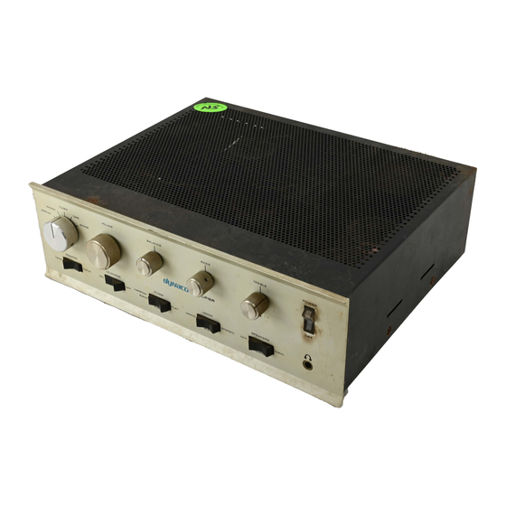
- Page 1 Updatemydynaco Dynaco SCA80(Q) Amplifier and Power Supply Upgrade (PWRAMP80) ASSEMBLY MANUAL © 2016-2017 AkitikA LLC All rights reserved Revision 1p18 November 25, 2017 Page 1 of 36...
-
Page 2: Table Of Contents
Table of Contents Table of Contents ........................ 2 Table of Figures ........................3 Section 1: About This Manual .................... 4 Who Should Attempt this Project? ................. 4 Tools you’ll need ......................4 Helpful Tools ........................4 Project Overview ......................4 Important Safety Notes .................... -
Page 3: Table Of Figures
Bare amplifier tests ....................26 Amplifier plus speaker tests ..................26 Amplifier plus speaker plus source tests ..............27 Final Assembly ......................27 In Case of Trouble ......................27 About the Design ......................28 Power Supply Theory of Operation ................28 Amplifier Board Theory of Operation .............. -
Page 4: Section 1: About This Manual
Section 1: About This Manual This manual gives the information needed to build and install the upgraded power supply and amplifier modules for either Dynaco’s SCA-80(Q) Integrated Amp. The is another manual that covers installation of this kit into a Stereo 80 Power Amp. -
Page 5: Important Safety Notes
2. Removing the old power supply 3. Installing and testing the new power supply 4. Installing and testing the new power amplifier 5. Completing re-assembly of the amplifier. Important Safety Notes By purchasing, using, or assembling this kit, you have agreed to hold Akitika LLC harmless for any injuries you may receive in its assembly and/or use. -
Page 6: Section 2: Kit Building Hints
Section 2: Kit Building Hints Yes, I know you want to ignore this section, and jump right into building the kit. However, please take a minute and read the advice. I’ve condensed it into bullets so that even you guys who are in a hurry can benefit. ... -
Page 7: Component Order
Figure 2-Silk screen shows power supply component locations Component Order You’ll notice that the component designations in the directions don’t go exactly in order. We have grouped them so that all components with the same value appear together. This makes assembly easier. You’ll find in the parts kit that similar parts, e.g. 3 1K resistors, are typically (though not always) taped together. -
Page 8: Install The Diodes
2. Bend the leads as described above. 3. Solder the leads on the back of the board. 4. Clip the leads. Track your progress by placing a check-mark in the done column as you install each component. Bend resistor leads to 0.45” width Designation Value Color Code... -
Page 9: Install The Optoisolator
Install the optoisolator The opto isolator comes in a 6-pin DIP (Dual Inline Package). Pin 1 on the PCB is indicated by the square pad. Pin 1 on the opto-isolator package can be identified by the dot on the package, refer to Figure 3. Make sure to install the opto with the correct orientation. -
Page 10: Install The Transistors
Install the Transistors Orient the transistor so its body shape matches the silk-screen outline. Leave the top of the transistor about ½” off the board! The lead length reduces stress on the body and keeps the transistor safe from too much heat during the soldering operation. Designation Type Description Done? () -
Page 11: Install The Rlydrv Wire
3. Twist and tin the 4 ends. 4. Insert one end of the red wire into the C9POS terminal from the component side of the board and solder it on the solder side. 5. Insert the accompanying black wire into the C9NEG terminal from the component side of the board and solder it on the solder side. -
Page 12: Sca80Q
3. De-solder and label these wires from PC19: a. Red transformer wire connected to pin 8. Label it with the “X1” label. b. Red transformer wire connected to pin 9. Label it with the “X2” label. c. Wire connected to pin 1. Label it with the “TOC11” label. 4. -
Page 13: Sca80 Directions
SCA80 Directions If you have an SCA80, then follow these directions. 8. There are two ground lugs that were fastened to the chassis by the mounting screw on the C9 side of PC-19. a. Find the lug that has two black wires that go to the amplifier modules and one white wire that goes to the negative terminal of C9. - Page 14 2. Desolder the wire connected to the RED terminal of C7L. 3. Desolder the wire connected to the BLACK terminal of C7L. Pull off the big hanging coil of wire. It will not be re-used. Locate the other side of that coil of wire where it connects to the front panel speaker switch.
-
Page 15: Install The New Power Supply
11. Identify the wire that connects to eyelet 1 of the front-most power amplifier channel. Clip that wire where it connects to eyelet 1, and label it RIGHTOUT. 12. Identify the wire that connects to eyelet 1 of the rear-most power amplifier channel. -
Page 16: Test The New Power Supply
Figure 6-Grounding arrangement for speaker common connections on the SCA-80 Test the New Power Supply Take a minute to clean up your work area before proceeding. Get a DC voltmeter ready to perform the following test: 1. Tape off the end of the yellow RLYDRV wire. 2. -
Page 17: Figure 7-Component Locations For The Stereo Amplifier Module
Figure 7-Component locations for the stereo amplifier module Bend resistor leads to 0.45” width Designation Value Color Code Done Brown, Black, Black, Black, Brown 100K Brown, Black, Black, Orange, Brown 100K Brown, Black, Black, Orange, Brown 100K Brown, Black, Black, Orange, Brown 100K Brown, Black, Black, Orange, Brown 100K... -
Page 18: Install The Diodes
24K9 Red, Yellow, White, Red, Brown 24K9 Red, Yellow, White, Red, Brown 24K9 Red, Yellow, White, Red, Brown 24K9 Red, Yellow, White, Red, Brown 24K9 Red, Yellow, White, Red, Brown 24K9 Red, Yellow, White, Red, Brown 24K9 Red, Yellow, White, Red, Brown 2K00 Red, Black, Black, Brown, Brown 2K00... -
Page 19: Install The Small Non-Polar Capacitors
Figure 8-Anode is the longer of the two leads Install the Small Non-polar Capacitors Note that the mounting hole space for the small COG caps is a big snug, but they’ll fit there nicely. Orientation of these caps does not matter. Designation Description Done? () 100 pF, axial, COG, marked 101... -
Page 20: Install The Transistors
Install the Transistors Orient the transistor so its body shape matches the silk-screen outline. Leave the top of the transistor about ½” off the board! The lead length prevents stress on the body and keeps the transistor safe from too much heat during the soldering operation. Designation Type Description Done? () -
Page 21: Build And Install The Inductor Resistor Combination
heat sink. Make sure that U1 sits level with respect to the PCB, then tighten the mounting screw. 3. Place a line of thermal compound onto the back of U2, an LM3886. Use your finger to smear the line into a thin film covering on the back of the LM3886. Save the rest of the thermal compound for other steps in the assembly. - Page 22 2. Wind the scraped portion of the magnet wire (about three turns) around one lead of the 10 Ohm 5 Watt resistor, near the body of the resistor. 3. Apply plenty of heat, and then solder the magnet wire to the resistor lead. 4.
- Page 23 chosen is not important. If you are within a turn or two of the ideal 16, you are fine. 6. If you have extra wire past the amount needed to make 16 turns and terminate the coil on the resistor lead, then cut the wire. You’ll probably cut no more than 1” off the wire.
-
Page 24: Install The Red/Black Zipcord Power Wires
12. Form the leads and install the second of these assemblies into the PCB as R20. Install the Red/Black Zipcord Power Wires 1. Cut a 9” length of the supplied 18 AWG red/black zip cord. 2. Strip ¼” inch of insulation from each of the four ends. 3. -
Page 25: Install The Power Amplifier
Figure 11-Assembled PCB with both heatsinks attached Install the power amplifier Prior to fastening the amplifier into the chassis: 1. Connect the yellow RLYDRV wire from the power supply to the RLYDRV eyelet on the right side of the power amplifier PCB. Insert it from the solder side, and solder it on the component side. -
Page 26: Test Your Work
c. Connect the Brown wire from the C7RNEG eyelet on the board to the negative terminal of C7R. C7R is near the front panel. d. Connect the White wire from the C7RPOS eyelet on the board to the positive terminal of C7R. C7R is near the front panel. 6. -
Page 27: Amplifier Plus Speaker Plus Source Tests
5. Turn off the amplifier. Amplifier plus speaker plus source tests 1. Connect a high level source like a CD player to the TUNER inputs. 2. Turn the volume down. 3. Turn the amplifier on. 4. After the relays click in, increase the volume to a comfortable listening level. Enjoy the music, but don’t get carried away. -
Page 28: About The Design
About the Design Power Supply Theory of Operation The power supply schematic is shown in Figure 15. Stepped down AC voltage from the transformer enters on the left side of the schematic through pins X1 and X2. These connect to D5-D8, which form a full-wave bridge that turns the AC input into pulsating DC. -
Page 29: Figure 12-Power Supply Snippet
Figure 12-Power supply snippet M1 is an N-channel MOSFET that turns on to energize the coils of the speaker relays found on the amplifier PCB. M1 turns on when its gate to source voltage, which is also the voltage across C1, gets a bit above M1’s threshold voltage, about 2.5 volts. R1 charges C1 rather slowly, over the course of a few seconds, to make this happen. -
Page 30: Figure 13-Dc Good Detector Snippet
Figure 13-DC Good Detector snippet DC Voltage Good Detection The following discussion refers to Figure 13. The DC Voltage good detector allows C1 to charge, and the relay to be energized, whenever VCC is greater than about 53 volts. Here’s how it works. R5 and R6 form a voltage divider that places 1/5 of VCC on the cathode of D3, a 10 Volt zener. -
Page 31: Figure 14-Ac Detect Snippet
Figure 14-AC Detect snippet Q3 turns on whenever the voltage Across C2 is greater than 1.2 volts. So we see there is an element of timing involved here. Every time a pulse at X1-X2 exceeds 40 volts, C2 discharges. If the power switch is turned off (or the plug is pulled), then there will be no input pulses, C2 charges, and C3 turns on, resetting C1. -
Page 32: Amplifier Board Theory Of Operation
Amplifier Board Theory of Operation VMID Generator The following discussion refers to Figure 16. The no-signal DC output voltage of the power amplifiers is set to half the supply voltage. That voltage appears across the clamp mounted C7s so that there is no DC voltage on the speakers. The VMID generator generates a clean and quiet voltage at half the supply voltage or approximately 36 volts. - Page 33 R12 provides DC bias current for the positive input. R7 and R8 set the power amp’s midband gain. C4, C9, and R16 civilize the behavior of the protection circuits when the amp is heavily loaded. R9 unmutes the power amplifier when adequate voltage is present. ...
-
Page 34: Figure 15-Power Supply Schematic
Figure 15-Power Supply Schematic Page 34 of 36... -
Page 35: Figure 16-Page 1 Of Amplifier Board Schematic
Figure 16-Page 1 of Amplifier Board Schematic Page 35 of 36... -
Page 36: Figure 17-Page 2 Of Amplifier Board Schematic
Figure 17-Page 2 of amplifier board schematic Page 36 of 36...
Need help?
Do you have a question about the PWRAMP80 and is the answer not in the manual?
Questions and answers