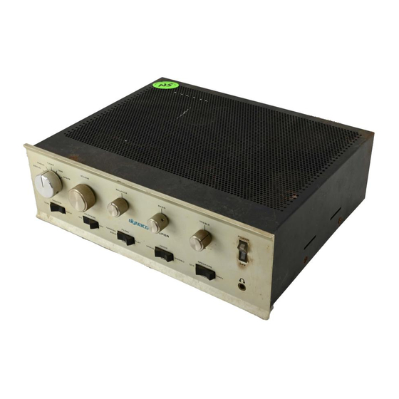
Summary of Contents for DYNACO SCA80
- Page 1 DYNACO SCA80(Q) C9 REPLACEMENT MANUAL © 2019 AkitikA, LLC All rights reserved Revision 2p01 April 30, 2019 Page 1 of 12...
-
Page 2: Table Of Contents
Table of Contents Section 1: About This Manual .................... 3 Who Should Attempt this Project? ................. 3 Tools You’ll Need......................3 Project Overview ......................3 Important Safety Notes ....................4 Section 2: Preliminaries ...................... 4 Opening the Amplifier ....................4 Check the Power Supply Voltage ................... -
Page 3: Section 1: About This Manual
Section 1: About This Manual Does your SCA80 hum a lot more than it used to? There’s a very good chance that its C9 has lost significant capacitance. This manual covers the replacement of the stock C9, a 5000 µF capacitor, with a total of 9900 µF. In addition to repairing hum problems, this gives any Dynaco SCA80Q better bass. -
Page 4: Important Safety Notes
First, you’ll need to safely check the power supply output voltage. 1. Turn the SCA80(Q) power switch off. 2. Keeping hands well clear of the inside of the SCA80(Q), plug in the power cord. 3. Turn the SCA80(Q) power switch on and give the amp about 15 seconds to stabilize. -
Page 5: Removing C9
If the voltage is more than 80 Volts, do not go on until you have determined why this might be so. There are a number of taps on the power transformer primary to support various line voltages. Your SCA80(Q) might have these taps mis-set for your prevailing voltage. This is especially possible if your amp is new to you, e.g. -
Page 6: Figure 3-Ground Harness Configuration
a. Remove 4” of insulation from the supplied 20 AWG wire. b. Cut the resulting bare wire into two 2” long pieces. c. Twist and shape the wires as shown in Figure 3. Figure 3-Ground Harness Configuration 6. Solder the center section as indicated. Place the soldered portion of the jumper in the center of the dynamite capacitor configuration. -
Page 7: Installing The New C9 Into The Amplifier
Installing the New C9 into the Amplifier 1. Install the clamp, capacitor, harness assembly into the amplifier. Use the keps nuts with the built in lockwashers (the 3 old nuts and lockwashers aren’t used). 2. Orient the new assembly as shown in Figure 5. Figure 5-Note the orientation of the capacitor assembly when installed into the amplifier Figure 6-Reconnecting the wires to the new C9 3. - Page 8 c. Wire 3 – green wire from the left amplifier channel to the other end of the positive harness. If this wire is too short to reach, extend it with a bit of the supplied red wire, and use heat shrink tubing to cover the joint. See Appendix 1 for details.
-
Page 9: Figure 7-Stock Amplifier Layout (Before C9 Replacement)
Figure 7-Stock amplifier layout (before C9 replacement) Page 9 of 12... -
Page 10: Figure 8-Stock Amplifier With Dynamite Capacitor Configuration Installed
Figure 8-Stock Amplifier with Dynamite Capacitor Configuration Installed Page 10 of 12... -
Page 11: Check And Test Your Work
3. Verify that the wires connected to the positive and negative terminals of C9 cannot, under any foreseeable circumstance, come into contact! 4. Place the rocker power switch in the SCA80(Q) in the ON position. 5. Plug the amplifier power cord into a power outlet. -
Page 12: Wire Splicing Using Heat Shrink Tubing
Appendix 1 Wire Splicing Using Heat Shrink Tubing 1. Form a hook in each wire to be spliced. 2. Interconnect and crimp the hooks. 3. Solder the hook connection. 4. Slide a 1” piece of heat shrink tubing over the connection, centering the heat shrink tubing about the connection.


Need help?
Do you have a question about the SCA80 and is the answer not in the manual?
Questions and answers