Table of Contents
Advertisement
Advertisement
Table of Contents

Related Manuals for GILBARCO VEEDER-ROOT Encore 700 S


Summary of Contents for GILBARCO VEEDER-ROOT Encore 700 S
- Page 1 Encore 700 S ® Start-up and Service Manual MDE-4902E...
- Page 2 Computer Programs and Documentation All Gilbarco Inc. and/or Veeder-Root Company computer programs (including software on diskettes and within memory chips) and documentation are copyrighted by, and shall remain the property of, Gilbarco Inc. and/or Veeder-Root Company. Such computer programs and documents may also contain trade secret information. The duplication, disclosure, modification, or unauthorized use of computer programs or documentation is strictly prohibited, unless otherwise licensed by Gilbarco Inc.
-
Page 3: Table Of Contents
Configuring/Activating Encore 700 S CRIND ........ - Page 4 Table of Contents Appendix B: Troubleshooting Encore 700 S CRIND Communication Issues CRIND Communication Problems ............B-1...
-
Page 5: Introduction
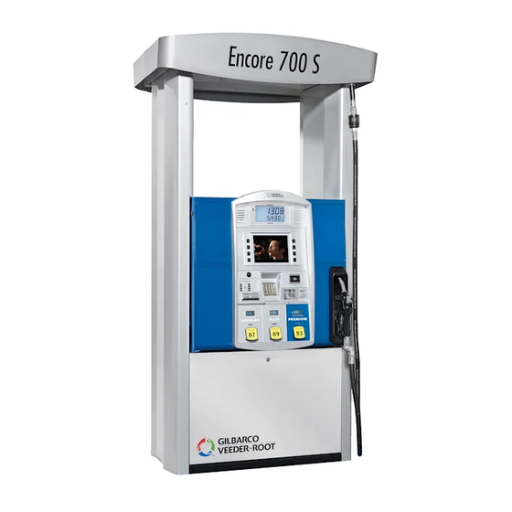
Figure 1-1: Encore 700 S CRIND System Encore 700 S CRIND System The Encore 700 S CRIND system is certified as Payment Card Industry-Unattended Payment Terminal (PCI-UPT) 1.X compliant and is designed to provide enhanced security to the fueling environment. The CRIND device uses a 5.7-inch color or 10.4-inch color display, FlexPay Encrypting PIN Pad (EPP) 2.1, and Secure Card Reader 2 (SCR 2). -
Page 6: Related Documents
• FlexPay IV IMPORTANT INFORMATION Installation and site preparation for the Encore 700 S is identical to that of the Encore 500 S. For installation and site preparation details, refer to MDE-3985 Encore Installation Manual, MDE- 3902 Call Button Kit K96636-01 for Encore Dispensers, and MDE-3802 Encore and Eclipse Site Preparation Manual. - Page 7 Abbreviations and Acronyms Introduction Term Description FlexPay Control Board GOLD Gilbarco Online Documentation ® Hub Interface PCB Internet Protocol Light Emitting Diode Local Operating Network Long Reach Ethernet ® Major Oil Company MSDS Material Safety Data Sheet OMAP Open Multimedia Applications Platform Printed Circuit Assembly Printed Circuit Board Payment Card Industry...
-
Page 8: Common Terms
Number (PIN) data for a debit account as entered by the customer. It is also capable of allowing other non-PIN data to be entered. Designed for EMV Canada, reused in Encore 700 S product. An independent council originally formed by American Express , Discover Financial Services, JCB, ®... -
Page 9: Important Safety Information
Important Safety Information 2 – Important Safety Information Notes: 1) Save this Important Safety Information section Read the Manual in a readily accessible location. Read, understand and follow this manual and any other labels or related materials supplied with this equipment. If you do not 2) Although DEF is non-flammable, Diesel is understand a procedure, call a Gilbarco Authorized Service flammable. - Page 10 Important Safety Information In an Emergency No Open Fire Inform Emergency Personnel Compile the following information and inform emergency Open flames from matches, lighters, welding torches or personnel: other sources can ignite fuels and their vapors. • Location of accident (for example, address, front/back of No Sparks - No Smoking building, and so on) •...
- Page 11 • Call emergency numbers. IMPORTANT INFORMATION • Before visiting a site for a field trial, the technicians servicing or installing the Encore 700 S must complete Gilbarco safety training. • Safety vests must be worn at all times when at the site.
- Page 12 Important Safety Information This page is intentionally left blank. Page 2-4 MDE-4902E Encore® 700 S Start-up and Service Manual · February 2018...
-
Page 13: Start-Up
Configuring CRIND Start-up 3 – Start-up Configuring CRIND Note: For more information on Encore 700 S Electronics CRIND Basic Input/Output System (BIOS), refer to MDE-4185 CRIND Encore 700 S Electronics CRIND BIOS Configuration Interface Manual. IMPORTANT INFORMATION The CRIND device on each side is programmed individually by inserting the CRIND Diagnostic Card (Q12534-170) on each side (cannot be done from the same side). -
Page 14: Crind Ids
Start-up CRIND IDs From the Main Menu, press 1 > Enter. The CRIND Config menu is displayed. Figure 3-2: CRIND Config Menu CRIND Config 1. CRIND IDs 2. CRIND Mode 3. Generic BAUD Rate 4. Force BIOS Coldstart 5. Force App Coldstart 6. -
Page 15: Crind Mode
CRIND Mode Start-up Press 1 > Enter. The CRIND ID Side 1 screen is displayed. (see Figure 3-4). Note: Each CRIND device is programmed separately by inserting the CRIND diagnostic card on each side (cannot be done from the same side). The CRIND ID screen is called “Side 1”... -
Page 16: Configuring Network For Sites With Dcm2 Or Earlier (Without Ssom)
Start-up Configuring Network for Sites with DCM2 or Earlier (without SSoM) Press the following numeric keys followed by Enter to change the current CRIND Mode setting: • 1 causes the unit to operate in Major Oil Company (MOC) CRIND Mode. •... - Page 17 Configuring Network for Sites with DCM2 or Earlier (without SSoM) Start-up The IP addressing scheme for the units without Secure System on Module (SSoM) is 10.5.55.XXX. FlexPay II DCM1.0 and DCM2.0 Unit Default IP Address Side A 10.5.55.71 Side B 10.5.55.72 Netmask 255.255.255.0...
-
Page 18: Configuring Network With Dcm2.1 (With Ssom) And Later Hardware
Start-up Configuring Network with DCM2.1 (with SSoM) and Later Hardware Configuring Network with DCM2.1 (with SSoM) and Later Hardware WARNING WARNING CRIND side IP addresses must not be changed from factory default unless one of the following three conditions apply: 1) The site requires a non-standard IP scheme. - Page 19 Configuring Network with DCM2.1 (with SSoM) and Later Hardware Start-up The IP addressing scheme for the units with SSoM is 172.16.100.XXX. FlexPay II DCM2.1 Unit Default IP Address Side A 172.16.100.1 Side B 172.16.100.3 Netmask 255.255.255.0 Default Gateway 172.16.100.254 SM Server 10.5.55.66 FlexPay IV DCM2.1 Unit...
-
Page 20: Resetting Default Ips
Start-up Configuring Network with DCM2.1 (with SSoM) and Later Hardware Resetting Default IPs From the Network Config menu, press 1 > Enter. This option resets all the IP addresses to the default value. The warning message as shown in Figure 3-8 is displayed before resetting the values to factory defaults. -
Page 21: Setting Ip Addresses
Configuring Network with DCM2.1 (with SSoM) and Later Hardware Start-up Setting IP Addresses From the Network Config menu, press 2 > Enter. The Set IP Addresses menu is displayed. IMPORTANT INFORMATION Both Side A IP address and Side B IP address must be programmed on each side of the dispenser. - Page 22 Start-up Configuring Network with DCM2.1 (with SSoM) and Later Hardware Setting CRIND Side B IP Note: Set CRIND Side B IP option is not visible on single side units. From the Set IP Addresses menu, press 2 > Enter. The CRIND Side B IP screen is displayed. Note: Side B will correspond with the side opposite of where you are standing.
- Page 23 Configuring Network with DCM2.1 (with SSoM) and Later Hardware Start-up To set SMART Merchandising Server IP address, number block must be in the 000-255 range and has to be completed with leading zeros as follows: • Press Clear to erase all entered digits and start again. •...
-
Page 24: Applying Network Settings
Start-up Configuring Network with DCM2.1 (with SSoM) and Later Hardware To set Gateway address, number block must be in the 000-255 range and completed with leading zeros as follows: • Press Clear to erase all entered digits and start again. •... -
Page 25: Viewing Network Settings
Configuring Network with DCM2.1 (with SSoM) and Later Hardware Start-up Viewing Network Settings From the Network Config menu, press 4 > Enter. The View Network Settings screen is displayed. This option enables to view the currently applied network settings. Figure 3-16: View Network Settings View Network Settings CRIND Side A 010.005.055.071 CRIND Other Side 010.005.055.072... - Page 26 Start-up Configuring Network with DCM2.1 (with SSoM) and Later Hardware Network Settings (Hidden) Press Enter. The Network Config screen is displayed. This option enables you to unhide the applied network settings. Figure 3-18: Network Settings (Hidden) Network Config Network settings hidden 1.
-
Page 27: Adjusting Audio Volume Level
Adjust the audio volume level on both sides of the unit individually. The audio must be set for all Encore 700 S CRIND units. Audio is used for Applause Media System functionality and for log collection for engineering troubleshooting purposes. Log collect utilizes audio prompting instructions. -
Page 28: Setting Default Personality
Start-up Setting Default Personality Setting Default Personality The personality screen is the background on the screen, that customers see during CRIND device prompting. The technician must verify with the customer the preferred personality screen before programming. To program the required personality screen as the default personality, proceed as follows: From the Main Menu on the CRIND device, press 6 >... -
Page 29: Setting Date And Time
Start-up Setting Date and Time Date and time must be set on the Encore 700 S CRIND devices. To set the date and time, proceed as follows: From the CRIND Config menu, press 6 > Enter. The Set Date/Time menu is displayed as... - Page 30 Start-up Setting Date and Time Press Enter to validate the new date/time and set the new time, if valid (that is, the day is not greater than the number of days in the given month, the month is less than 13, and so on). ~ OR ~ Press Cancel to return to the CRIND menu.
-
Page 34: Service
Service Encore 700 S Block Diagrams Figure 4-4: Block diagram for DCM2.2 Two-Wire Configuration (Dedicated) Page 4-4 MDE-4902E Encore® 700 S Start-up and Service Manual · February 2018... - Page 35 Encore 700 S Block Diagrams Service Figure 4-5: Block diagram for DCM2.2 Two-Wire Configuration (Non-Dedicated) MDE-4902E Encore® 700 S Start-up and Service Manual · February 2018 Page 4-5...
-
Page 36: Diagnostics And Visual Checks (After Installation)
Service Diagnostics and Visual Checks (After Installation) Diagnostics and Visual Checks (After Installation) Diagnostics Mode Run System Health Report (press Clear and swipe the CRIND diagnostic card, verify the settings and ensure that the pump and door node versions are displayed). Ensure that printer works, all CRIND options required are enabled, IP address, ... -
Page 37: Encore 700 S Pcbs
Encore 700 S PCBs Service Encore 700 S PCBs Figure 4-6 shows the PCB details for Encore 700 S. Figure 4-6: Easylon USB Socket Interface (EIA 485) Board [M07713A001 (USB to LON ® Board)] USB Connector Pin 1-1/10 inch Pitch... - Page 38 Green blinking Normal communication Error Figure 4-7 shows the Encore 700 S Peripheral Interface PCB (PIP). Figure 4-7: Encore 700 S PIP (M09112A001) Printed Circuit Assembly (PCA) Connect to Pump Download To Cash Acceptor Port (A Side only) To TRIND...
- Page 39 Encore 700 S PCBs Service Board Connections and Cables The following table lists the connection details: Connector# Via Cable To Board At Connector # P203 M07970A002 M01922A003 P111 (Side A only) P311 M07974A002 M09115A001 P411 P214 M09266A001 M09115A001 P414 P312...
- Page 40 Service Encore 700 S PCBs Figure 4-8 shows the beeper interface PCA. Figure 4-8: Beeper Interface PCA (M09232A001) USB Connection from UPT CRIND. Used for USB/Serial Connection on P203. Connect to Pump Beep Input from Download UPT CRIND Port (Side A...
- Page 41 Encore 700 S PCBs Service Figure 4-9 shows the HIP interface PCA. Figure 4-9: HIP Interface PCA (M07895A001) Connector to Cash Acceptor Two-wire Connection to Pump for MOC Mode To P402 on A Side Two-wire Connection to POS Field Wiring for Applause Media System...
- Page 42 Service Encore 700 S PCBs Figure 4-10 shows the HIP 2 interface PCA. Figure 4-10: HIP 2 Interface PCA Two-wire Connection to Connector to Cash Acceptor Pump for MOC Mode To P402 on Side A CRIND two-wire connection to...
- Page 43 Encore 700 S PCBs Service Board Connections and Cables The following table lists the connection details: Connector# Via Cable To Board At Connector# P302A M07702A016 M09115A001 P402 (Side A only) P302B M07702A016 M09115A001 P402 (Side B only) P403 M01922A003 J1109...
- Page 44 Service Encore 700 S PCBs Figure 4-11 shows the intercom interface PCA. Figure 4-11: Intercom Interface PCA (M09751A002) This connector provides Power, Intercom Connection, and the Speaker Output from the UPT CRIND Board (M09229). JP2* = 16 seconds JP3* = 32 seconds To Speaker *The intercom board will be in “customer talk”...
- Page 45 Encore 700 S PCBs Service Figure 4-12 shows the barcode scanner interface PCA. Figure 4-12: Barcode Scanner Interface PCA (M10402A001) Note: This board is part of the Scanner Assembly (M07662A002/A003) and is not sold separately. Board Connections and Cables The following table lists the connection details:...
-
Page 46: Flexpay Control Board [Fcb (M11930K001)]
Service FlexPay Control Board [FCB (M11930K001)] FlexPay Control Board [FCB (M11930K001)] The FCB provides the functions of CRIND device. The FCB houses the secure device that protects credit and debit card PIN information. The FCB is located on the main door directly behind the CRIND display (see Figure 4-13). - Page 47 FlexPay Control Board [FCB (M11930K001)] Service Board Connections and Cables The following table lists the connection details: Connector# Via Cable To Board At Connector# P411 M10453A001 M07895A001 J301A, J301B P603 M10453A001 M10371A001 P504 M09259A001 P502 M06745A003 M04219A001 P503 Q13850-06 M07895A001 J312A, J312B P506 M07957A004 M10206B001,...
- Page 48 Service FlexPay Control Board [FCB (M11930K001)] The following table lists the LED/jumper and their functions: LED/Jumper Function The Encrypted Card Reader (ECR) LEDs are active and indicate communication to SCR/ECR. Pump/PRN The Pump/PRN LEDs indicate communication to the pump node. In Generic Mode, the Pump/PRN LEDs stay in a steady-state (either OFF or ON) and do not blink.
-
Page 49: Dcm2.2
DCM2.2 Service DCM2.2 DCM2.2 (M15737A001) Highlights Figure 4-15: DCM2.2 Board J3 HomePlug New Location JP12 - New SmartCRIND P333 - New Connector for JP5 - New Jumper for VLAN JP6 - New Jumper for Pump Jumper Dedicated High-Speed (UX410) Current Loop Selection New - These ports become dedicated for specific devices when VLAN Jumper is installed (printed on the PCB) DCM2.2 LED Functions... -
Page 50: Dcm2.2 Led Indicators
Service DCM2.2 DCM2.2 LED Indicators Check the following LED indicators after DCM2.2 is powered ON: Function Color Control CCP Power_Good LED Green Driven when 2.5 V, 3.3 V and 5 V are present HomePlug Power LED Green ON: Power ready Flashing: Loading firmware OFF: Power not ready HomePlug Status LED... -
Page 51: Dcm2.2 Jumpers
DCM2.2 Service DCM2.2 Jumpers The following table lists the status and functions of jumpers: Connector Function High-speed connection active. P304 A/B disabled. High-speed connection inactive. P304A and P304B connects to Category 5 (CAT-5) running through the conduit for high speed connection (if used). Unit is connected to a Passport POS MOC Unit is connected to a third party POS (Generic) VLAN is enabled (FlexPay II only) - Page 52 Service DCM2.2 This page is intentionally left blank. Page 4-22 MDE-4902E Encore® 700 S Start-up and Service Manual · February 2018...
-
Page 53: Activating Encore 700 S Crind
When replacing a FlexPay EPP on an Encore 700 S unit, the FlexPay EPP extracts the mapping and key information from the FCB. However, an activation with Gilbarco is required. -
Page 54: Configuring/Activating Encore 700 S Crind
Configuring/Activating Encore 700 S CRIND Configuring/Activating Encore 700 S CRIND To activate an Encore 700 S CRIND, you must enter the service menu. To enter the Service menu and perform the activation, proceed as follows: Power up the Encore 700 S CRIND device. The Product Part Number (PPN) is displayed on... - Page 55 Configuring/Activating Encore 700 S CRIND Activating Encore 700 S CRIND The Service Menu is shown when the Encore 700 S CRIND requires activation (see Figure 5-4). Otherwise, a white screen with the Gilbarco logo and software package versions is displayed momentarily (see Figure 5-3).
- Page 56 Press 2 > Enter to enter the Security Setup Menu. This menu is used to activate security mounting sensors. The Encore 700 S CRIND software modules are not activated and system communications are not possible until the unit’s mounting sensors are activated.
- Page 57 Note: To obtain a password, call the Gilbarco Call Center at 1-800-800-7498 and inform the associate that you have an Encore 700 S CRIND device that requires activation. Enter the matching password into the Security Setup Menu and press OK. After you enter the password correctly, the system will show the sensors’...
- Page 58 The activation procedure must be repeated. At each power up, if the Encore 700 S CRIND main processor detects a module that is not activated, it will automatically enter the Service Menu (green screen). For a description of the various diagnostics screens, refer to “Appendix A: Diagnostic Screens”...
-
Page 59: Appendix A: Diagnostic Screens
Appendix A: Diagnostic Screens At power up, if you cannot access the Service Menu, one of the following diagnostic messages is displayed on the Encore 700 S CRIND screen. Yellow Screen This indicates that the system has found an active package in its memory and has started to install it. -
Page 60: Blue Screen
Figure A-3: Blue Screen Green Screen This indicates that the system is running but has not been activated through the commissioning process. In this situation, the Encore 700 S CRIND will automatically enter the Service Menu. Figure A-4: Green Screen Page A-2... -
Page 61: Appendix B: Troubleshooting Encore 700 S Crind Communication Issues
CRIND Communication Problems Troubleshooting Encore 700 S CRIND Communication Issues Appendix B: Troubleshooting Encore 700 S CRIND Communication Issues CRIND Communication Problems Symptom Potential Causes Check/Remedy “Lost Key” LED glows on FCB Security compromised or corrupt FCB. Replace FCB assembly. -
Page 62: Crind Communication Problems
Troubleshooting Encore 700 S CRIND Communication Issues CRIND Communication Problems Symptom Potential Causes Check/Remedy SCR not responding. Card reader, cabling, and POS system. Check “ECR” LEDs are on SPP (both TX and RX must be flashing). If ECR LEDs flashing, then try swiping a credit or debit card to ensure that the condition still exists. - Page 63 CRIND Communication Problems Troubleshooting Encore 700 S CRIND Communication Issues Symptom Potential Causes Check/Remedy Insite360 Encore not receiving Verify that the Z-Modem cable is connected at P315 and on any incremental logs from PCN, P1111 at the PCN (excludes E300 and Advantage).
- Page 64 Troubleshooting Encore 700 S CRIND Communication Issues CRIND Communication Problems This page is intentionally left blank. Page B-4 MDE-4902E Encore® 700 S Start-up and Service Manual · February 2018...
-
Page 65: Appendix C: Encore 700 S Start-Up Checklist
Encore 700 S Start-up Checklist Appendix C: Encore 700 S Start-up Checklist IMPORTANT INFORMATION • Press Enter after each character (for example, for CRIND ID 10, press 1 > Enter, 0 > Enter, and Enter). If the card reader is not responding, close the main doors to eliminate any outside... - Page 66 Encore 700 S Start-up Checklist TRIND: Verify the response obtained with handheld transponder tester. Note: Verify that in Encore 300/500 (square bezel) NGP retrofit applications, “Enable Wireless Sync Option” is set to “Enabled”. Without this option enabled, TRIND units can interfere with each other. For more information, ...
- Page 67 Encore 700 S Recommended Spare Parts Appendix D: Encore 700 S Recommended Spare Parts The following table lists the recommended spare parts for Encore 700 S: Distributor Part Description Part Number FCB in Plastic Housing M11930K001 Beeper Interface Board M09232A001 Display, Color 5.7”...
-
Page 68: Appendix D: Encore 700 S Recommended Spare Parts
Encore 700 S Recommended Spare Parts This page is intentionally left blank. Page D-2 MDE-4902E Encore® 700 S Start-up and Service Manual · February 2018... -
Page 69: Appendix E: Flexpay Ii Crind Retrofit Trind Settings
FlexPay II CRIND Retrofit TRIND Settings Appendix E: FlexPay II CRIND Retrofit TRIND Settings The TRIND utilizes a Gateway PCA (T20678-G3) to route the traffic of microreader communication with overlapping read fields prior to installation of the FlexPay II Retrofit Kit. Following the installation of FlexPay II Retrofit Kits: •... - Page 70 FlexPay II CRIND Retrofit TRIND Settings This page is intentionally left blank. Page E-2 MDE-4902E Encore® 700 S Start-up and Service Manual · February 2018...
- Page 71 Index Index M08631K001 D-1 PPN 5-4 M09112A001 4-7, 4-15 auxiliary keypad C-1 M09115A001 4-9, 4-13, 4-14 R20773-G4 4-9 M09193A002 D-1 Red Screen A-1 Blue Screen A-2 M09232A001 D-1 M09259A001 4-14 M09266A001 4-9 security mounting sensors 5-4 CRIND 1-4, 3-1, 3-3, D-1 M09281A001 4-9 System Health Report C-1 M09751A002 D-1...
- Page 72 American Express is a registered trademark of American Express Company. Easylon is a registered trademark of Gesytec GmbH. EMV ® ® ® i a registered trademark of EMVCo LLC. Ethernet is a registered trademark of Xerox Corporation. Europay and MasterCard ®...
Need help?
Do you have a question about the Encore 700 S and is the answer not in the manual?
Questions and answers
instructions for putting a gilbarco encore 700s in stand alone