Table of Contents
Advertisement
Quick Links
Download this manual
See also:
Product Manual
Advertisement
Table of Contents

Subscribe to Our Youtube Channel
Related Manuals for Contemporary Research ICC1-IR


Summary of Contents for Contemporary Research ICC1-IR
- Page 1 Product Manual ICC1-IR IR TV Controller, 1-way RF Coax Control Ver. 5.1 September 30, 2008 17630 Davenport Road, Suite 113 • Dallas, TX 75252 Phone: 972-931-2728 • Toll-Free: 888-972-2728 • Fax: 972-931-2765 E-Mail: Sales@crwww.com • Website: www.crwww.com...
-
Page 2: Table Of Contents
Command String Structure ... 10 RS-232 Commands ... 11 iC-Net SmartZones... 13 System Map ... 14 Typical RF and ICC-Net Signal Flow ... 15 Safety Instructions ... 16 Limited Warranty and Disclaimer ... 17 Contemporary Research ICC1-IR IR TV Controller... -
Page 3: Overview
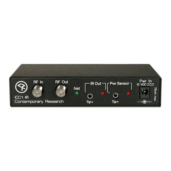
The ICC1-IR IR TV Controller delivers economical 1-way control for TV power, volume, and channels, receiving iCC-Net network commands over the same broadband coax that carries the CATV channels. Compact in size and price, the ICC1-IR features sensed power on/off control and intelligent tuning from a channel list stored in onboard non-volatile memory. -
Page 4: Specifications
3.5mm plug, 4ft. cable, stick-on TV sensor Includes CC-HSD Scan Sensor CC-IRE IR Emitter RF Loop cable, 18” 12 VDC power supply, 100 mA, (domestic US shipments only) Mounting Velcro for unit and CC-HSD Contemporary Research ICC1-IR IR TV Controller... -
Page 5: Installation
If needed, fix CATV problems before installing the system. 2. Connect the CATV RF Coax cable into the RF In input on the iCC1-IR. 3. If the iCC-Net signal is operating, the Net LED will blink once per second. -
Page 6: Setting Ir Control Codes (Ir Type Mode)
Setting IR Control Codes (IR Type Mode) The DIP switches S1 and S1 at the bottom of the ICC1-IR serve in two modes, IR Type, Channel Entry and Device Number, determined by S2 Switch 6 and S2 Switch 5. In this section, you’ll set up the manufacturer’s IR codes sent from the IR Out port. -
Page 7: Ir Control Codes
PC Sensor Setup: LCD marked PC Sensor (Power Current Sensor) do not have discrete IR power commands. Instead, the ICC1-IR will wait for an “OFF” signal from a power sensor before it sends an ON IR command. We recommend the Power Current Sensor sold by Display Devices, absolute power control. -
Page 8: Setting Device Number And Parameters (Device Mode)
Setting Device Number and Parameters (Device Mode) In the next step, you’ll need to set up the device number and operation parameters for the ICC1-IR. Notice that the functions of the S1 and S2 switches change when you set the unit in Device mode. -
Page 9: Unit Address Settings
1. Connect the CC-IRE IR Emitter plug into the IR Out jack. 2. Mount the emitter cube to the TV case where the TV receives IR commands. 3. Mount the ICC1-IR to the TV using included Velcro tape. 4. Connect DC power to unit. -
Page 10: Rs-232 Control Protocol
Each TV Controller is assigned a unique device number from 1 to 4000 to which control commands are addressed. The devices are organized into 16 zones of 255 devices. All the devices in each zone will respond to a single “virtual device number”... -
Page 11: Rs-232 Commands
Identical to using DIP switch to set IR control codes. Specify value to match IR code type. Add 64 to the IR code to set the ICC1-IR to ignore the power sensor – if the type is specified as Sensor – discrete types always ignore the sensor input. - Page 12 Locks power operation – only functional with display with power current sensor. When the control is locked, the display is locked to the power state of the ICC1-IR. For example, if the ICC1-IR power state is off, the display can’t be turned on from the IR remote or TV front panel.
-
Page 13: Ic-Net Smartzones
The ICC1-IR and ICC1-232 controllers typical for many SignStream display control systems are designed to follow a Zone address format. You can use the 4 top switches in the second DIP switch (S2) to define the controller’s Zone. -
Page 14: System Map
E154 1024 E251 1025 E252 1024 E253 1025 E254 1026 1280 G100 1281 G150 1282 G151 1283 1536 TV 1 1537 TV 2 1538 1792 1793 1794 1795 1796 2048 Admin 2049 A/V Center 2050 4095 ICC1-IR IR TV Controller... -
Page 15: Typical Rf And Icc-Net Signal Flow
Typical RF and ICC-Net Signal Flow The diagram below shows the structure of a typical Contemporary Research media retrieval system. One of the key aspects for iCC-Net communication is to provide a forward and return (sub-channel) path for data if you’re using ICC2 2-way TV Controllers. -
Page 16: Safety Instructions
Article 820-40 of the National Electrical Code (Section 54 of Canadian Electrical Code, Part I), that provides guidelines for proper grounding and, in particular, specifies that the cable ground shall be connected to the grounding system of the building as close to the point of cable entry as possible. Contemporary Research ICC1-IR IR TV Controller... -
Page 17: Limited Warranty And Disclaimer
Limited Warranty and Disclaimer Contemporary Research Corporation (CR) warrants this product to be free from defects in material and workmanship under normal use for a period of two years from the date of purchase from CR. Should such a defect occur CR will repair or replace, at their option, the defective product at no cost for parts or labor.
Need help?
Do you have a question about the ICC1-IR and is the answer not in the manual?
Questions and answers