
Related Manuals for Contemporary Research ICC1-232


Summary of Contents for Contemporary Research ICC1-232
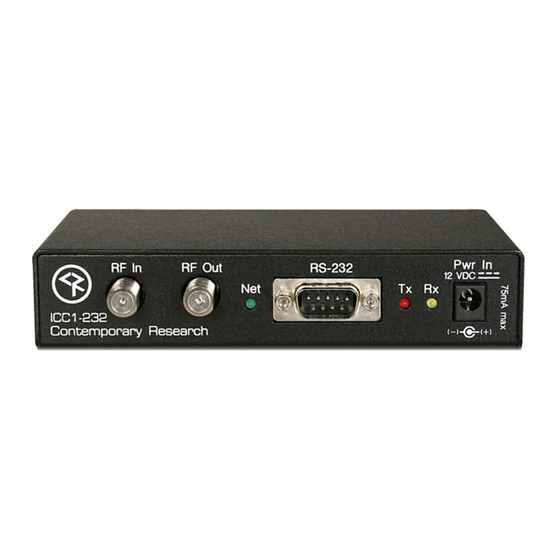
- Page 1 Product Manual ICC1-232 RS-232 Display Controller, 1-way Control Ver. 2.5 February 09, 2009...
-
Page 2: Table Of Contents
Overview ...7 Command String Structure ...7 RS-232 Commands ... 8 iC-Net Zones ... 10 System Map ... 11 Typical RF and ICC-Net Signal Flow ... 12 Safety Instructions ... 13 Limited Warranty and Disclaimer ... 14 Contemporary Research ICC1-232 Manual... -
Page 3: Overview
CATV channels. Compact in size and price, the ICC1-232 features discrete power control and intelligent tuning from a channel list stored in onboard non-volatile memory. Tuning options include analog- and HDTV-format channels. -
Page 4: Specifications
RF Loop cable, 18" 12 VDC power supply, 100 mA, (domestic US shipments only) Mounting Velcro Options CC-232 RS-232 Control Cable (specify make, model, and length) 12 VDC power supply, 100 mA, (domestic US shipments only) Mounting Brackets Contemporary Research ICC1-232 Manual... -
Page 5: Installation
If needed, fix CATV problems before installing the system. 2. Connect the CATV RF Coax cable into the RF In input on the ICC1-232. 3. If the iCC-Net signal is operating, the Net LED will blink once per second. -
Page 6: Setting Rs-232 Control Codes
Setting RS-232 Control Codes The DIP switches S1 and S1 at the bottom of the ICC1-232 serve in two modes, IR Type, Channel Entry and Device Number, determined by S2 Switch 6 and S2 Switch 5. In this section, you’ll set up the manufacturer’s IR codes sent from the IR Out port. -
Page 7: Setting Device Number And Parameters (Device Mode)
Setting Device Number and In the next step, you’ll need to set up the device number and operation parameters for the ICC1-232. Notice that the functions of the S1 and S2 switches change when you set the unit in Device mode. -
Page 8: Unit Address Switch Settings
It’s much easier to pre-configure ahead of time than perform the task once the displays are installed. RS-232 Control Wiring 1. Connect the CC-232 cable from the ICC1-232 to the display. 2. Mount the ICC1-232 to the TV using included Velcro tape. -
Page 9: Rs-232 Control Protocol
In ABC-Net, we reserve the first group of devices, 1-255, for components operating on a connected control system. Zones 1-16 are used for CR TV Controllers, Video Display Controllers and Tuners. As it’s unlikely any system will use all 4000 devices, this may be a good device standard for your system as well. -
Page 10: Rs-232 Commands
3 = Physical HD Major-Minor tuning (physical channel, minor digital) TC Response “$A5,<dh>,<dl>,3,’H2’,<response>” (7 bytes) This pre-sets how the ICC1-232 will respond to TC tuning commands. 0= Ignore, use current settings 1= Analog Only 2= Digital (For CableCard applications only) Control String "$A5,<dh>,<dl>,2+string length>,'UX'<string>"... - Page 11 Tune HD “$A5,<dh>,<dl>,5,’TH’,<H1>,<Major>,<Minor>” (9 bytes) – Digital Tuning Normally, the H1 parameter is 0, allowing the ICC1-232 to use the current H1 tuning format, but it could be used to force a different tuning option. When the display is set to the H1=1 mode, the Major-Minor bytes will represent the high and low bytes of the 5-digit number.
-
Page 12: Ic-Net Zones
The ICC1-IR and ICC1-232 controllers typical for many SignStream display control systems are designed to follow a Zone address format. You can use the 4 top switches in the second DIP switch (S2) to define the controller’s Zone. -
Page 13: System Map
E152 E153 E154 1024 E251 1025 E252 1024 E253 1025 E254 1026 1280 G100 1281 G150 1282 G151 1283 1536 TV 1 1537 TV 2 1538 1792 1793 1794 1795 1796 2048 Admin 2049 A/V Center 2050 4095 ICC1-232 Manual... -
Page 14: Typical Rf And Icc-Net Signal Flow
Typical RF and ICC-Net Signal Flow The diagram below shows the structure of a typical Contemporary Research media retrieval system. One of the key aspects for iCC-Net communication is to provide a forward and return (sub-channel) path for data if you’re using ICC2 2-way TV Controllers. -
Page 15: Safety Instructions
Article 820-40 of the National Electrical Code (Section 54 of Canadian Electrical Code, Part I), that provides guidelines for proper grounding and, in particular, specifies that the cable ground shall be connected to the grounding system of the building as close to the point of cable entry as possible. Contemporary Research ICC1-232 Manual... -
Page 16: Limited Warranty And Disclaimer
Limited Warranty and Disclaimer Contemporary Research Corporation (CR) warrants this product to be free from defects in material and workmanship under normal use for a period of two years from the date of purchase from CR. Should such a defect occur CR will repair or replace, at their option, the defective product at no cost for parts or labor.
Need help?
Do you have a question about the ICC1-232 and is the answer not in the manual?
Questions and answers