
Related Manuals for ASL INTERCOM BS 17


Summary of Contents for ASL INTERCOM BS 17
- Page 1 BS 17 – S INGLE HANNEL ELTPACK User Manual !"#$"%&'()*+' ,*-)'...
-
Page 2: Table Of Contents
Table of contents 1.0 GENERAL DESCRIPTION ..................... 3 2.0 INSTALLATION ...................... 3 3.0 TOP PANEL CONTROLS .................... 4 4.0 SIDE PANEL CONTROLS .................... 4 5.0 BOTTOM PANEL CONNECTORS .................. 5 6.0 TECHNICAL SPECIFICATIONS .................. 6 7.0 BS 17 BLOCK DIAGRAM ..................... 7 8.0 PARTY LINE, TECHNICAL CONCEPT ................ 8 9.0 CABLING ........................ 8 10.0 SYSTEM CONFIGURATION ..................10 11.0 EARTHING CONCEPT .................... 11... -
Page 3: General Description
To connect the BS 17 to the intercom system, use professional microphone cable with 2 wires and 1 shield. The for the BS 17 necessary DC voltages are derived from the inter- com master station or power supply via the interconnecting cables. -
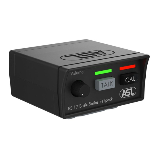
Page 4: Top Panel Controls
TOP PANEL CONTROLS VOLUME control knob To adjust the listen level for the head- TALK button This push button activates the head- set mic. which is indicated by the large green LED. CALL button This push button activates the call system. -
Page 5: Bottom Panel Connectors
BOTTOM PANEL CONNECTORS LINE connectors (XLR-3) These XLR-3 connectors are for con- necting the BS 17 to the party line in- tercom system. The female XLR is the intercom line input and the male XLR is for extending the intercom line to other user stations (‘daisy chaining’). -
Page 6: Technical Specifications
Max output power: 1.3 Wrms @ 200 Ω • Side Tone Rejection: 0 – 30 dB adjustable • Buzzer Max. SPL: 85 dBA at 0.1m • BS 17 Power Consumption (@ 30V DC) 18 mA quiescent, 35 mA signalling •... -
Page 7: Bs 17 Block Diagram
80 mA at max. output + signaling • BS 17 Dimensions & Weight Width: 78 mm / Height: 46 mm • Depth: 86 mm / Weight: 145 grams • 0 dB is defined as 775 mV into open circuit ASL reserves the right to alter specifications without prior notice... -
Page 8: Party Line, Technical Concept
PARTY LINE, TECHNICAL CONCEPT User stations and power supplies in an ASL intercom system are connected via one or several 'party lines'. A party line offers two-way (‘full duplex’) communication and consists of standard micro- phone (multi-pair) cable. One wire is used as an audio line, one as a power line and the screen of the cable functions as earth/return. - Page 9 Use high quality cable Use high quality microphone cable (shielded two conductor cable, minimum 2x 0.30 mm2). In case multi-pair microphone cable is used, there should be an overall shield and each pair should consist of two conductors (minimum 2x 0.15 mm2) with separate shield Use flexible cable Use flexible single and multi-pair microphone cable instead of cable with solid cores, especially when the cable is subjected to bending during operation or installation.
-
Page 10: System Configuration
ASL powered units to a 'clean' mains outlet Master stations or power supplies should be connected to a mains outlet with a clean earth. Other audio equipment may be connected to this mains outlet, but avoid using an outlet which also powers dimmer controlled lighting systems. -
Page 11: Earthing Concept
11.0 EARTHING CONCEPT Designed and manufactured by: ASL Intercom BV Zonnebaan 42, 3542 EG Utrecht, The Netherlands Phone: +31 (0)30 2411901 Fax: +31 (0)30 2667373 ⎪ E-mail: info@asl-inter.com www.asl-inter.com Web: ⎪...
Need help?
Do you have a question about the BS 17 and is the answer not in the manual?
Questions and answers