Table of Contents
Advertisement
Available languages
Available languages
Quick Links
Advertisement
Table of Contents

Related Manuals for S&P PULSE 160


Summary of Contents for S&P PULSE 160
- Page 1 PULSE 160 EN DA...
-
Page 2: Observaciones Generales
Una vez El modelo PULSE 160 es apto para utilizar en sis- fi nalizada la instalación entrégueselo al usuario temas de ventilación controlada de edifi cios resi- fi... -
Page 3: Resumen Del Sistema
2. RESUMEN DEL SISTEMA 2.1. FUNCIONAMIENTO En general, las habitaciones húme- Siempre que sea posible, el PULSE 160 se deberá requieren la instalación de dos unidades. utilizar por pares, con una unidad para introducir el Este sistema no es apto para habita- aire fresco y otra para expulsar el aire usado. -
Page 4: Herramientas Necesarias
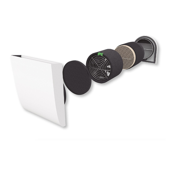
Núm. artículo Salida de aire interna Filtro para polvo 3.4. HERRAMIENTAS NECESARIAS Unidad de ventilación Para la instalación del PULSE 160 se necesitan las Intercambiador de calor siguientes herramientas: PULSE • Sierra de corona de Ø 162 mm Filtro previo •... -
Page 5: Instalación Eléctrica
Se pueden conectar hasta cua- conducto adicional para llevar el cable hasta la tro unidades PULSE 160 a una unidad de control. caja de fusibles. Si se necesitan más de cuat ro unidades de PULSE 160, se requerirán grupos independientes adicio-... - Page 6 Morado Para conectar el PULSE CONTROL 160 con las Azul Conexión a tierra unidades PULSE 160 debe usar un conector de 3 pines de 3,5 mm entre cables. El cableado incorrecto puede provo- car daños a la unidad de ventilación.
- Page 7 Recubra el exterior del tubo de montaje con el INTERIOR EXTERIOR producto sellador (2) e insértelo en el orifi cio (3). Preste atención al tiempo que necesita el produc- to sellador para secarse. Proceda a realizar el si- guiente paso. Asegúrese de que el tubo de mon- taje esté...
-
Page 8: Funcionamiento Del Sistema
6. FUNCIONAMIENTO DEL SISTEMA 5.5. COLOCACIÓN DE LA UNIDAD DE VENTILACIÓN Y DEL INTERCAMBIADOR DE 6.1. PULSE 160 CALOR La cubierta interior se puede cerrar en caso de que no vaya a utilizar el sistema durante un pe- ríodo de tiempo largo o de que quiera evitar que el... - Page 9 6.1.1. Cierre de la cubierta interior Paso 1: Tire de la cubierta interior hacia fuera del tubo de montaje. Paso 1: Tire de la cubierta interior hacia fuera del tubo de montaje. Paso 2: Tire de la solapa para sacarla de la espu- ma fl...
-
Page 10: Limpieza Y Mantenimiento
Modo Eco Activa el modo de Para garantizar un funcionamiento efi ciente de recuperación de calor. su PULSE 160, deberá comprobar los componen- Modo máxima Activa el modo de máxima tes y llevar a cabo el mantenimiento regular de potencia potencia. - Page 11 7.2.2. Mantenimiento del ventilador Nunca desconecte la clavija del ventilador tirando del cable. Utilice unos alicates y tire de la clavija. 7.2.1. Mantenimiento de los fi ltros para polvo Paso 1: Tire de la cubierta interior hacia fuera del tubo de montaje. Paso 1: Tire de la cubierta interior hacia fuera del tubo de montaje.
-
Page 12: Resolución De Problemas
Paso 5: Vuelva a introducir la cubierta interior (con Paso 5: Vuelva a introducir el intercambiador de la entrada de aire apuntando hacia arriba) en el calor en el tubo de montaje, con cuidado de no da- tubo de montaje. ñar los cables situados en el interior del mismo. -
Page 13: Servicio Técnico
Fallo Causa Solución Fallo Causa Solución Cubierta inte- • Abrir la cubierta Falta de • Reiniciar el suminis- rior cerrada. interior. corriente. tro de energía. Filtro obs- • Limpiar o sustituir Error de insta- • Comprobar el truido. el fi ltro. lación. -
Page 14: General Remarks
ENGLISH 1. GENERAL REMARKS 1.2. USAGE The PULSE 160 is suitable for use in the contro- Thank you for placing your confi dence in S&P by lled ventilation of residential buildings. PULSE buying this product. It has been manufactured 160 usage is authorized solely in accordance with... -
Page 15: Installation Preparations
(ca. 15-20 2.1. FUNCTIONING mm) or the use of ventilation grilles. Wherever possible, PULSE 160 should be operated in pairs; with one unit blowing in fresh air and the other expelling spent air. The units change direc-... - Page 16 Foam support ring Mounting tube 500 mm 3.5. POSITIONING Outside air outlet The best position for the PULSE 160 is determined in the project planning phase. Please pay atten- 3.2. PULSE CONTROL PRO COMPONENTS tion to the minimum distances, as otherwise no guarantee can be given that the units will function properly.
-
Page 17: Electrical Installation
CONTROL 160 (units available separately). the cable to the fuse box. Up to six PULSE 160 units can be connected to a PULSE CONTROL 160 system in a star confi gura-... -
Page 18: Connection And Wiring
If more than six PULSE 160 units are to be in- 5.1.1. Use of a core-drilled hole tegrated into a housing unit, a second independent control must be added. The PULSE CONTROL 160 can be placed anywhe- re. Connection cables must be 3 poles, it is re- commended that a LiYY data cable be used. - Page 19 Measure the thickness of the wall. Should any Wire the plug for connecting up the fan unit (see plastering still need to be done, allow for plaster Electrical installation). Should cables with a dia- meter › 6.1 mm be used, the top layer of insula- thickness when shortening the mounting tube.
-
Page 20: Operating The System
6.1.2. Opening the inside cover 6. OPERATING THE SYSTEM 6.1. PULSE 160 The inside cover can be shut, should you not use the system over a longer period or should you want to prevent smoke for instance entering the room. -
Page 21: Cleaning And Maintenance
6.2.2. Operating modes and functions Eco-Mode Operating in pairs, the units change airfl ow direction every 50-70 seconds dependent on the selected fan speed, ensuring heat reco- very. Full-blast mode The system runs in just one direction, allowing a room to be thoroughly ventilated. Step 3: Reattach the fl... -
Page 22: Maintenance Instructions
Component Interval What is to be done Fan unit Once a • Clean the fan unit year using a brush fi rst, then a vacuum cleaner. Step 3: check the fi lter. When necessary, clean or Heat Once a • Use a vacuum replace it. - Page 23 Step 2: Unplug the fan (1). Pull the fan unit out of the mounting tube using the strap (2), taking care that the power cable is not damaged. Step 3: Using a brush and a vacuum cleaner, clean the fan grille and the rotor blades. Step 3: Pull the heat exchanger unit out of the mounting tube using the strap, taking care that the power / sensor cable is not damaged.
-
Page 24: Troubleshooting
8. TROUBLESHOOTING Fault Cause Remedy Inside cover is • Open the inside Fault Cause Remedy shut. cover. Control unit • Set the controls Filter clogged up. • Clean the fi lter or operating in "full- to eco-mode replace it. blast" mode. (heat recovery). -
Page 25: Generelle Bemærkninger
EU-standarder. Læs venligst PULSE 160 er velegnet til kontrolleret ventilation denne brugsanvisning omhyggeligt inden insta- i boliger. Brug af PULSE 160 er kun tilladt i ove- llation og opstart af produktet. Brugsanvisningen rensstemmelse med de beskrevne typer brug og... - Page 26 2.1. FUNKTION (ca. 15-20 mm) eller ved brug af Hvor det er muligt, skal PULSE 160 betjenes par- ventilationsgitre. vist, hvor den ene enhed trækker frisk luft ind, og den anden blæser brugt luft ud. Enhederne skifter retning samtidig efter 50 - 70 sekunder (afhængigt...
- Page 27 • Hammer og mejsel til kabelkanaler / spalter Monteringsrør 500 mm 3.5. POSITIONERING Ekstern luftudgang Den bedste position for PULSE 160 bestemmes under projektplanlægningsfasen. Vær opmærk- 3.2. PULSE CONTROL PRO-KOMPONENTER som på minimumsafstandene, da det ellers ikke kan garanteres, at enhederne fungerer korrekt.
-
Page 28: Elektrisk Installation
Sørg for, at al ledningsføring udføres med en styreenhed, der kan købes separat. Der korrekt. kan tilsluttes op til fi re PULSE 160-enheder til en Ventilator 1 Ventilator 3 styreenhed. Hvis der er behov for mere end fi re PULSE 160-enheder, skal der anvendes yderlige- re uafhængige grupper, der styres af andre styre-... - Page 29 tion. Hvis fl ere enheder ønskes tilkobles kan end- 5.1.1. Med et kerneboret hul nu en PULSECONTROL tilføjes. PULSE control 160 kan placeres over alt. Kabel skal være 3 polet. Det kan anbefales at et LiYY data kabel anvendes. For at sikre en passende spænding må længden mellem ventilator og styreenhed ikke overstige 100 m (eksempel på...
- Page 30 Mål væggens tykkelse. Skulle der stadig være brug se minus 150 mm. Forbind stikket for at tilslutte for gipsarbejde, skal der være plads til gipsens ventilatorenheden (se Elektrisk installation). Hvis tykkelse, når monteringsrøret afkortes. Afkort der anvendes kabler med en diameter på over 6,1 monteringsrøret ved hjælp af en bajonetsav på...
- Page 31 6. DRIFT AF SYSTEMET 6.1.2. Åbning af det indvendige dæksel 6.1. PULSE 160 Det indvendige dæksel kan lukkes, hvis du ikke skal bruge systemet i en længere periode, eller hvis du fx skulle ønske at forhindre røg i at komme ind i rummet.
-
Page 32: Rengøring Og Vedligeholdelse
Pil op/ON Øger ventilatorhastigheden 7. RENGØRING OG VEDLIGEHOLDELSE og/eller tænder for systemet. For at sikre, at din PULSE 160 fungerer effektivt, Automatisk Aktiverer / deaktiverer skal alle komponenter kontrolleres og vedligehol- tilstand automatisk tilstand. des regelmæssigt. - Page 33 7.1. VEDLIGEHOLDELSESINTERVALLER Komponent Interval Hvad skal der gøres Inde i En gang • Rengør overfl aden med gitteret hver tredje en fugtig klud. måned Støvfi lter En gang • Brug en støvsuger til at hver tredje fjerne støv fra fi lteret. måned •...
- Page 34 Trin 2: Frakobl ventilatoren (1) Træk ventilatoren- Trin 2: Frakobl ventilatoren (1). Træk ventilato- heden ud af monteringsrøret ved hjælp af stroppen renheden ud af monteringsrøret ved hjælp af (2), sørg for, at strøm- / kontrolkablet ikke beska- stroppen (2), sørg for, at strømkablet ikke beska- diges.
- Page 35 Skub ventilatorenheden ind i monteringsrøret, Fejl Årsag Løsning indtil afstandsstyk-kerne berører varmeveksleren (2). Installations- • Kontroller kabler og fejl. ledninger. • Kontroller, at styreenheden er installeret korrekt. Styreenheden Strømfor- • Udskift strømforsy- fungerer ikke. syningen ningen. fungerer ikke korrekt. Trin 7: Sæt det indvendige dæksel ind (luftindtaget Styreenheden •...
-
Page 36: Teknisk Support
Fejl Årsag Løsning La unidad • Vælg Eco-mode de control (varmegenvinding) está en modo på styreenheden. “máxima Aire de entra- potencia”. da frío. Falta el inter- • Indsæt varmevek- cambiador de sler-enheden. calor. 9. TEKNISK SUPPORT Hvis produktet ikke tændes, eller hvis det fungerer unormalt eller er unormalt støjende, skal du koble produktet fra strømmen ved at indstille kontakten “0/1”... -
Page 37: Bezpečnostní Informace
ČESKY 1. ÚVOD 1.2. POUŽITÍ PULSE 160 je vhodný pro použití při řízeném větrá- Děkujeme za důvěru ve společnost S&P, kterou jste ní obytných budov. Použití PULSE 160 je povoleno projevili zakoupením tohoto produktu. Produkt je výhradně v instalacích, které jsou v souladu s tímto vyroben dle platných technických bezpečnostních... -
Page 38: Příprava Montáže
Prostor pod dveřmi (cca 15 - 20 2.1. PROVOZ mm) nebo použití ventilačních mřížek. PULSE 160 by měl být provozován v páru, tam kde je to možné. Jedna jednotka přivádí čerstvý vzduch Obecně lze říci, že místnosti s výs- a druhá... - Page 39 • Kladivo a majzlík pro vedení a prostupy kabelů Pěnový kroužek Instalační potrubí 500 mm 3.5. UMÍSTĚNÍ Venkovní mřížka Nejlepší je určit umístění PULSE 160 ve fázi návr- hu. Věnujte prosím pozornost minimálním odstu- 3.2. KOMPONENTY ŘÍDÍCÍ JEDNOTKY PULSE pům, protože jinak nelze zaručit správnou funkci CONTROL PRO jednotek.
-
Page 40: Elektrická Instalace
Jednotky PULSE 160 lze provozovat pouze ve spo- jení s řídicí jednotkou, která se dodává samostat- ně. K jedné řídicí jednotce lze připojit až čtyři jed- Černá notky PULSE 160. V případě potřeby řízení více než Napájení jednotky Červená čtyř jednotek PULSE 160, jsou zapotřebí další ne- závislé... - Page 41 LiYY Pro dodržení hodnoty odpo- 5.1.1. Vyvrtání díry do stěny vídajícího napájení nesmí délka kabelů přesáhnout 100m. Příklad zapojení šesti jednotek PULSE 160. Napájecí adaptér Řídící jednotka Vyvrtejte do zdi díru pomocí jádrové vrtačky a ko- 4.4. SCHÉMA ZAPOJENÍ...
-
Page 42: Připojení Kabelů
Změřte tloušťku stěny. Pokud je třeba ještě dodě- 5.4. INSTALACE KRYCÍ MŘÍŽKY NA VNĚJŠÍ STRANĚ lat omítky, při zkracování instalačního potrubí je třeba počítat s tloušťkou omítky. Zkraťte instalační potrubí pomocí kotoučové pily tak, aby konce in- stalačního potrubí byly zarovnány s vnitřní i vněj- ší... - Page 43 Před uvedením do provozu musí být 6.1.2. Otevření vnitřní mřížky vložen prachový nebo pylový fi ltr. 6. OBSLUHA ZAŘÍZENÍ 6.1. PULSE 160 Pokud nebudete systém delší dobu používat nebo Krok 1: Sejměte vnitřní mřížku z instalačního potrubí. pokud chcete zabránit například vniknutí kouře do místnosti lze vnitřní...
-
Page 44: Čištění A Údržba
Otáčky Zobrazuje ručně zvolené 7. ČIŠTĚNÍ A ÚDRŽBA ventilátoru otáčky nebo otáčky automaticky nastavené čidlem vlhkosti. Pro zajištění správné funkce PULSE 160 musí být všechny komponenty pravidelně kontrolovány a Šipka Nahoru/ Zvýšení otáček ventilátoru udržovány. Zap. a/nebo zapnutí systému. Automatický... -
Page 45: Pokyny Pro Údržbu
7.2. POKYNY PRO ÚDRŽBU V průběhu údržby musí být zařízení vypnuto. V průběhu údržby ventilátoru musí Krok 5: vyjměte předfi ltr, vyčistěte ho a vložte ho zpět. být ventilátor odpojen od elektric- kého napájení. Poznámka: po několika vyčištěních obou fi l- trů... - Page 46 napájecího/ datového kabelu. Zapojte ventilátor (1). Zatlačte ventilátor do instalačního potrubí, až zapadne do tepelného výměníku (2). Krok 4: Vyčistěte výměník tepla vysavačem a prou- dem teplé vody. Vodu omyjte pouze keramickou část a výměník osušte. Krok 5: Vložte vnitřní mřížku do instalačního po- trubí.
-
Page 47: Řešení Problémů
8. ŘEŠENÍ PROBLÉMŮ Chyba Příčina Náprava Uzavřená • Otevřete vnitřní Chyba Příčina Náprava vnitřní mřížka. mřížku. Řídící jednotka • Nastavte režim Zanesený fi ltr. • Vyčistěte nebo nastavena na “eco” (rekupe- vyměňte fi ltr. režim "full- race). Zanesený • Vyčistěte výměník blast". -
Page 48: Varnostne Informacije
Zahvaljujemo se vam za zaupanje v S&P z naku- nem prezračevanju stanovanjskih objektov. Upo- pom tega izdelka. Izdelan je z veljavnimi tehnič- raba PULSE 160 je dovoljena izključno v skladu z nimi varnostnimi predpisi v skladu z EC standardi. opisanimi primeri uporabe in samo v povezavi s Pred namestitvijo in zagonom izdelka natančno... -
Page 49: Pregled Sistema
2.1. DELOVANJE pod vrati (približno 15-20 mm) ali Kjer je le mogoče, je treba PULSE 160 upravljati v uporabo prezračevalnih rešetk. paru; pri čemer ena enota dovaja svež zrak, druga pa odvaja izrabljeni zrak. Enote spreminjajo smer sočasno po 50-70 sekundah (odvisno od izbrane... - Page 50 Podporni obroč iz pene 3.5. POZICIONIRANJE Montažna cev 500 mm Zunanja odvodna maska Najboljši položaj za PULSE 160 je določen v fazi načrtovanja projekta. Prosimo, bodite pozorni na najmanjšo razdaljo, saj sicer ne moremo jamčiti, 3.2. KOMPONENTE PULS CONTROL PRO da bodo enote pravilno delovale.
- Page 51 Na eno krmilno enoto je mogoče priključiti Pulse 1 Pulse 3 do šest enot PULSE 160. Kjer je potrebno več kot šest enot PULSE 160, bodo potrebne dodatne neodvisne skupine enot, ki jih upravljaja ločena krmilna enota. Krmilno enoto lahko namestite Črna...
- Page 52 0,75 mm²). Za zagotovitev ustrezne moči, dolžina 5.1.1. Uporaba izvrtane luknje kabla med krmilno enoto in ventilatorsko enoto ne sme presegati 100 m. Primer ožičenja šestih PULSE 160. Adapter Krmilnik 230 V AC V steno izvrtajte luknjo s svedrom z 162 mm nastav- kom.
- Page 53 Izmerite debelino stene. Če je še treba na steno 150 mm. Priključite vtič za priključitev ventilatorja (glejte Električna napeljava). Če uporabljate kable dodati omet, pri krajšanju pritrdilne cevi upošte- s premerom ›6,1 mm, bo treba odstraniti zgornjo vajte debelino ometa. Z žago skrajšajte pritrdilno plast izolacije, da preprečite težave pri nadaljnji cev tako, da se konci pritrdilne cevi prilegajo tako namestitvi.
- Page 54 4. korak: Znova vstavite notranjo masko v pritrdil- no cev. 6. UPRAVLJANJE SISTEMA 6.1.2. Odpiranje notranje maske 6.1. PULSE 160 Notranjo masko lahko zaprete, če sistema ne upo- rabljate dlje časa ali če želite preprečiti, da bi na primer dim vstopil v sobo.
-
Page 55: Čiščenje In Vzdrževanje
Puščica dol / Zmanjša hitrost ventilatorja in / ali izklopi sistem. Eco-Mode Aktivira način rekuperacije toplote. Full-blast mode Aktivira način polnega vpiha. Sleep mode Aktivira način spanja. 2. korak: Izvlecite loputo iz prožne pene. Filter change Uporabniku pove, naj display zamenja fi... -
Page 56: Navodila Za Vzdrževanje
7.1. VZDRŽEVALNI INTERVAL Komponenta Interval Kaj je treba storiti Notranja Enkrat na • Obrišite površino z rešetka tri mesece vlažno krpo. Prašni fi lter Enkrat na • S sesalcem tri mesece odstranite prah s fi ltra • Nato ga umijte s toplo vodo 2. - Page 57 2. korak: Odklopite ventilator (1) Izvlecite venti- 2. korak: Odklopite ventilator (1) Izvlecite venti- latorsko enoto iz pritrdilne cevi s trakom (2), pri latorsko enoto iz pritrdilne cevi s trakom (2), pri čemer pazite, da napajalni / krmilni kabel ne bo čemer pazite, da napajalni / krmilni kabel ne bo poškodovan.
-
Page 58: Odpravljanje Napak
Napaka Vzrok Rešitev Notranja loputa • Odprite notranjo je zaprta. loputo Zamašen fi lter • Očistite fi lter ali ga zamenjajte Enota • Očistite enoto Nizka izmenjevalca izmenjevalca toplote stopnja toplote je • Očistite pretoka umazana prezračevalno enoto 7. korak: Znova vstavite notranjo masko (dovod zraka Prenizka hitrost •... - Page 60 S&P SISTEMAS DE VENTILACIÓN, S.L.U. C. Llevant, 4 Polígono Industrial Llevant 08150 Parets del Vallès Barcelona - España Tel. +34 93 571 93 00 Fax +34 93 571 93 01 www.solerpalau.com Ref. 1441374-2...
Need help?
Do you have a question about the PULSE 160 and is the answer not in the manual?
Questions and answers