Table of Contents
Advertisement
Quick Links
Please dispose of packaging for the product in a responsible
HG3000S SWF
manner. It is suitable for recycling. Help to protect the
environment, take the packaging to the local amenity tip and
place into the appropriate recycling bin.
Mig Inverter Welder
Never dispose of electrical equipment or batteries in with your
domestic waste. If your supplier offers a disposal facility please
use it or alternatively use a recognised re-cycling agent. This will
allow the recycling of raw materials and help protect the environ-
ment.
FOR HELP OR ADVICE ON THIS PRODUCT PLEASE CONTACT YOUR DISTRIBUTOR,
OR SIP DIRECTLY ON:
05777
TEL: 01509500400
EMAIL: sales@sip-group.com or technical@sip-group.com
www.sip-group.com
Please read and fully understand the instructions in this manual
before operation. Keep this manual safe for future reference.
Ref: 220817
36
1
Advertisement
Table of Contents

Related Manuals for SIP HG3000S SWF


Summary of Contents for SIP HG3000S SWF
- Page 1 This will allow the recycling of raw materials and help protect the environ- ment. FOR HELP OR ADVICE ON THIS PRODUCT PLEASE CONTACT YOUR DISTRIBUTOR, OR SIP DIRECTLY ON: 05777 TEL: 01509500400 EMAIL: sales@sip-group.com or technical@sip-group.com www.sip-group.com...
- Page 2 LE12 9NH England As the manufacturer's authorised representative within the EC declare that the Product Enquiry HG3000S SWF Mig Inverter Welder - SIP Part No. 05777 Conforms to the requirements of the following directive(s), as indicated. 2006/95/EC Low Voltage Directive 2004/108/EC...
-
Page 3: Table Of Contents
NOTES CONTENTS Page No. Description Safety Symbols Used Throughout This Manual Safety Instructions Electrical Connection Guarantee Technical Specification Contents and Accessories Getting to Know Your Welder Assembly Instructions Operating Instructions Maintenance Troubleshooting Wiring Diagram Exploded Drawing - Main Unit Parts List - Main Unit Exploded Drawing - WFU &... -
Page 4: Safety Symbols Used Throughout This Manual
The welder should not be modified or used for any application other than that for V-groove V-groove V-groove U-groove U-groove which it was designed. SIP Part No. WE02-00382 WE02-00119 WE02-00438 WE02-00445 WE02-00446 This welder was designed to supply electric current for Mig or Arc welding. - Page 5 USE ONLY RECOMMENDED ACCESSORIES: Consult this user manual, your distributor or SIP directly for recommended accessories. Follow the instructions that accompany the accessories. The use of improper accessories may cause hazards and will invalidate any warranty you may have.
- Page 6 DO NOT EXPOSE THE WELDER TO RAIN OR USE IT IN WET CONDITIONS: Water entering the welder will greatly increase the risk of electric shock and equipment damage. Ref. No. Description Sip Part No. Ref. No. Description Sip Part No.
- Page 7 EXPLODED DRAWING - WFU & INTERCONNECTIONS SAFETY INSTRUCTIONS….cont ELECTRIC SHOCK Electric welders have the potential to cause a shock that could lead to injury or death. Touching electrically ‘hot’ parts can cause fatal shocks and severe burns; While weld- ing, all metal components connected to the welder are electrically ‘hot’. Keep your body and clothing dry.
- Page 8 PARTS LIST - MAIN UNIT least 10 metres away and out of the reach of sparks and heat or protect Ref. No. Description Sip Part No. Ref. No. Description Sip Part No. against ignition with suitable and snug fitting, fire resistant covers or shields.
- Page 9 EXPLODED DRAWING - MAIN UNIT SAFETY INSTRUCTIONS….cont without gloves. First aid facilities and a qualified first aid person should be available for each shift unless medical facilities are close by for immediate treatment of flash burns to the eyes and skin. Flammable hair products should not be used by persons intending to weld.
- Page 10 WIRING DIAGRAM SAFETY INSTRUCTIONS….cont Vapours from chlorinated solvents can be decomposed by the heat of the arc (or flame) to form phosgene a highly toxic gas and other lung and eye-irritating products. The ultra violet (radiant) energy of the arc can also decompose tri- chloroethylene and perchlorethylene vapours to form phosgene.
-
Page 11: Electrical Connection
Note: If none of the above solutions work then contact your local distributor The wire which is coloured yellow / green should be connected to the terminal which for repair, or contact SIP technical for more advise. is coloured the same or marked with this symbol Always secure the wires in the plug terminal carefully and tightly. -
Page 12: Guarantee
Liner nut Hold the torch as straight as possible. This SIP mig welder is covered by a 24 month parts and labour warranty covering fail- Push the new liner back through the torch. ure due to manufacturers defects. This does not cover failure due to misuse or operat- Re-fit the liner nut. -
Page 13: Technical Specification
TECHNICAL SPECIFICATION WELDING - ARC Note: In order to arc (MMA) weld with the welder, you will need to purchase an electrode holder and lead - SIP part number 10230. Model SIP HGT3000S SWF Caution: Ensure all protective equipment is worn and bystanders are not in... -
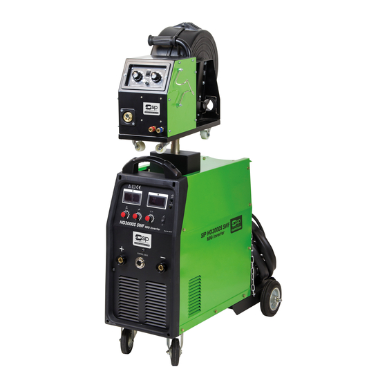
Page 14: Contents And Accessories
CONTENTS AND ACCESSORIES OPERATING INSTRUCTIONS….cont HG3000S SWF Mig Inverter Welder. ARC WELDING HG3000S Wire Feed Unit (separate box). There are no hard and fast rules by which a particular gauge of electrode is selected, Instruction Manual. usually this is determined by the type of welding required and the thickness of the MB25 Mig Torch. - Page 15 OPERATING INSTRUCTIONS….cont GETTING TO KNOW YOUR WELDER nents might become too high due to over use; The internal thermal protector will then prevent the unit from operating. Its Intervention is Indicated by the alarm light on the front panel, If this happens leave the machine switched on with the fan running and allow It to cool down.
-
Page 16: Getting To Know Your Welder
GETTING TO KNOW YOUR WELDER ….cont OPERATING INSTRUCTIONS….cont Feed the wire through the inlet guide spring, over the wire feed rollers and WIRE FEED UNIT through the guide tubes (you may need to straighten the first 50mm or so of wire if it doesn't fit in to the guide tube easily). - Page 17 OPERATING INSTRUCTIONS….cont ASSEMBLY INSTRUCTIONS FEEDING THE WIRE FITTING & CONNECTING THE WIRE-FEED UNIT Before feeding the wire, you should ensure that the correct wire feed rollers are fitted. Remove the wire-feed unit from its box. To check / change the roller: Remove the packaging from the main unit.
-
Page 18: Assembly Instructions
ASSEMBLY INSTRUCTIONS….cont ASSEMBLY INSTRUCTIONS….cont Connect both parts at the opposite end of the interconnecting cable to the FITTING THE TORCH HOLDER front of the welder (see below). Retaining Screws Loosen the torch holder retaining screws. Note: Connect the lead to the positive (+) terminal for standard welding Fit the torch holder.
Need help?
Do you have a question about the HG3000S SWF and is the answer not in the manual?
Questions and answers