
Subscribe to Our Youtube Channel
Related Manuals for Parker Pure Water Series


Summary of Contents for Parker Pure Water Series
- Page 1 Village Marine-PW 400-2000 Part Number: 95-0025 Pure Water Series PW 400-2000 GPD Installation, Operation & Maintenance...
- Page 3 THE PURE WATER SERIES 400-2000 GPD USER GUIDE & REFERENCE MANUAL...
-
Page 5: Table Of Contents
INTRODUCTION UNPACKING AND HANDLING PERFORMANCE SPECIFICATIONS ENVIROMENTAL REQUIREMENTS CONSUMABLES MAINTENANCE EQUIPMENT INSTALLATION TO INSTALL THE PURE WATER UNIT TO CONNECT PLUMBING TO CONNECT THE ELECTRICAL GENERAL THEORY OF OPERATION REVERSE OSMOSIS THEORY APPLICATION OF REVERSE OSMOSIS PRODUCT WATER QUALITY STANDARDS FACTORS AFFECTING PERMEATE PRODUCTION TEMPERATURE CORRECTION FACTOR OPERATIONAL DESCRIPTION... - Page 6 TO FLUSH THE PURE WATER UNIT MEMBRANE CLEANING CLEANING CHEMICALS WHEN TO CLEAN STEPS FOR CHEMICAL CLEANING #1: HIGH pH CLEANER STEPS FOR CHEMICAL CLEANING #2: LOW pH CLEANER LONG TERM STORAGE / PRESERVATION PROCEDURE STEPS FOR PRESERVATION CHEMICAL #3 OIL CHANGE PROCEDURE RO MOTOR LUBRICATION MEMBRANE REPLACEMENT...
- Page 8 SYSTEM START UP LOG Village Marine Tec. Fresh Water from the Sea SYSTEM START UP LOG SYSTEM INFORMATION MODEL NUMBER: SERIAL NUMBER: DATE OF PURCHASE: PURCHASED FROM: INSTALLATION DATE: START UP PERFORMANCE READINGS: MEASURE AFTER 3 AND 24 HOURS OR PRESSURIZED TIME IN SIMILAR CONDITIONS 3 Hours 24 Hours FEED WATER TEMPERATURE:...
-
Page 10: Introduction
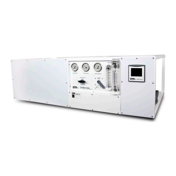
INTRODUCTION INTRODUCTION SYSTEM DESCRIPTION Village Marine Tec’s (VMT ) Pure Water watermakers are well-engineered reverse osmosis (RO) systems, designed and built for simple operations and maintenance for the cruising sailor, sport fisherman, or working vessels where space is at a premium. These self-contained AC desalination systems will produce sixteen to eighty-three gallons per hour (GPH) of freshwater from the sea (gallon production will vary based upon water temperature, salinity, and model of the RO system). -
Page 11: Unpacking And Handling
INTRODUCTION UNPACKING AND HANDLING The Pure Water reverse osmosis units are shipped pre-assembled. There are no special instructions towards unpacking and handling of the watermaker system. Inspect the RO unit to verify it was not damaged in transit. Also, please refer to the plumbing diagram in Section 9.0: DRAWINGS AND DIAGRAMS to verify all components for the watermaker are shipped prior to installation. -
Page 12: Consumables
INTRODUCTION CONSUMABLES Table 1.2 lists the consumables required for operation of the RO unit. Use ONLY Village Marine Tec approved filters and chemicals. Further parts information can be found in section 10. PW 200-600 PW 800-2000 Description VMT P/N. VMT P/N Chemical Cleaning Kit #1, #2, &... -
Page 13: Installation
INSTALLATION INSTALLATION Village Marine Tec. recommends ALL Pure Water models (as with all other VMT model RO units) be INSTALLED BELOW the vessel’s waterline, to ensure a flooded suction intake to the unit. 2.1a TO INSTALL THE PURE WATER UNIT Village Marine Tec. -
Page 14: To Connect Plumbing
INSTALLATION The Pure Water FRAME SHOULD NOT SHARE a through-hull feedwater intake. Avoid connecting the inlet piping to any water line which services an engine or other equipment. Air could be drawn through the unit causing damage to the RO unit’s pumps, as well as VOIDING the RO unit’s warranty with VMT. - Page 15 INSTALLATION Figure 2.5: Pure Water FRAME (PWF600-PWF2000) Manifold – Left View. FEEDWATER INTAKE AND FRESH WATER FLUSH Units with MANUAL Freshwater Flush Assembly: Mount the three-way manual Freshwater Flush Valve Assembly (attached to the Carbon Filter Housing) BELOW waterline. Refer to Figure 2.6 for views of the Carbon Filter and Freshwater Flush Valve. Figure 2.6: Carbon Filters with Freshwater Flush Valves –...
- Page 16 INSTALLATION Figure 2.7: Separated Freshwater Flush Valve for ABOVE Waterline Connection. Figure 2.8: Manual Freshwater Flush Standard Configuration With Valve Connected. Units with AUTOMATIC Freshwater Flush Assembly: Mount the check valve component of the Automatic Freshwater Flush Valve Assembly BELOW waterline.
- Page 17 INSTALLATION Refer to Figures 2.10 or 2.11 for a diagram of the Automatic Freshwater Flush Assembly. Figure 2.10: Typical Automatic Freshwater Flush Valve Assembly (PW400-PW600) Diagram. Figure 2.11 Automatic Freshwater Flush Valve Assembly Diagram for PW800-PW2000.
- Page 18 INSTALLATION BRINE DISCHARGE Locate a convenient spot in the boat to install an overboard through-hull. Discharge line is required to be ABOVE waterline (Refer to Figures 2.1, 2.12, 2.13 and 2.14). Figure 2.12: PURE WATER Brine Connection Overboard. Figure 2.13: Pure Water SEMI-MODULAR Brine Connection Overboard.
- Page 19 INSTALLATION Figure 2.14: Pure Water MODULAR Brine Connection Overboard. PRODUCT WATER The product water hose line must go into the top of the product tank to prevent any possible back flow. Village Marine Tec. recommends teeing into the tank fill line. Teeing into the tank vent line is possible if the vent is sufficient diameter to let air out of the tank while filling.
-
Page 20: To Connect The Electrical
INSTALLATION Figure 2.16: Pure Water SEMI-MODULAR Product Water Hose Connection. Figure 2.17: Pure Water MODULAR Product Water Hose Connection. 2.1c TO CONNECT THE ELECTRICAL TURN OFF ALL ELECTRICAL POWER FOR USE WITH THE RO UNIT PRIOR TO CONNECTING TO THE RO POWER SOURCE. FAILURE TO DO SO MAY RESULT IN SERIOUS INJURY OR DEATH TO PERSONS HANDLING THE UNIT. -
Page 21: General Theory Of Operation
GENERAL THEORY GENERAL THEORY OF OPERATION REVERSE OSMOSIS THEORY Reverse osmosis, like many other practical scientific methods, was developed from processes first observed in nature. Osmosis is a naturally occurring phenomenon in which a semi-permeable membrane separates a pure and a concentrated solution (a semi-permeable membrane is defined as one that preferentially passes a particular substance). -
Page 22: Product Water Quality Standards
GENERAL THEORY In a Reverse Osmosis desalination system, most of the dissolved solids do not pass through the membrane but are instead carried along the membrane surface. This rejected water, referred to as brine, becomes increasingly more concentrated as it flows across the surface of the membranes and is eventually piped to drain. -
Page 23: Factors Affecting Permeate Production
GENERAL THEORY FACTORS AFFECTING PERMEATE PRODUCTION VARIATIONS IN TEMPERATURE, PRESSURE, AND SALINITY The following table illustrates how the quality and quantity of permeate produced by a RO system is affected by changes in temperature, salinity and pressure: Permeate With constant..And increasing.. -
Page 24: Temperature Correction Factor
GENERAL THEORY 3.4a TEMPERATURE CORRECTION FACTOR As previously described, the output capacity of any RO unit is highly dependent on feedwater temperature. In order to quantify this relationship, operational data has been utilized to develop Temperature Correction Factors (TCF). The TCF (which is compensated to 25°C/77°F) is used to determine what part of any change in system output flow is due to variations in feedwater temperature alone. -
Page 25: Operational Description
GENERAL THEORY Note: Before July, 1st 2015 OPERATIONAL DESCRIPTION: ppm/NaCl Figure 3.2: Water Quality Monitor - Panel View. Figure 3.3: Master Control Center - Panel View. ppm/NaCl Figure 3.4: Optional Remote Control Center – Panel View. Figure 3.5: Product Solenoid Valve. PRODUCT WATER MONITORING SYSTEM The product water (or permeate) flows past a conductivity sensor which provides a signal to the water quality monitor. -
Page 26: Pushbutton And Display Descriptions
GENERAL THEORY Installed as an option, the Remote Control Center (RCC) provides remote control and monitoring of all important unit functions and operating parameters (Figure 3.4) from a remote location. The RCC has a similar configuration as the MCC with the exception of the Message Center and Reset Pushbutton. PUSHBUTTON AND DISPLAY DESCRIPTIONS Refer to the numerical callouts of Figures 3.2-3.5 for reference of the following pushbutton and displays explanation of the Water Quality Monitor, Master Control Center, and Remote Control Center panels. - Page 27 GENERAL THEORY When the water monitor detects high saltwater content, a signal is sent to the MCC and the message “CHECK PRODUCT WATER” is displayed. Additionally, the MCC illuminates the “HIGH SALINITY” light. (12) CHECK UNIT The MCC will send a signal to the RCC when its internal counters activate any of the following alarms: Check Oil, Change Flush Filter or Clean Membranes.
- Page 28 GENERAL THEORY Note: After July, 1st 2015 OPERATIONAL DESCRIPTION Figure 3.2: Touch screen display for Master Control Center and Remote Control Center. Figure 3.3: Three-Way Product Valve. PRODUCT WATER MONITORING SYSTEM The product water (or permeate) flows past a conductivity sensor which provides a signal to the Master Control Center.
- Page 29 GENERAL THEORY If the permeate TDS has LESS than 500 ppm, indicating GOOD (drinking) water, a signal is sent to the three-way product diversion valve to redirect the good permeate through a flowmeter and finally into your water storage tank(s). MASTER CONTROL CENTER The Master Control Center (MCC) provides centralized control and monitoring of all important unit functions and operating parameters (Figure 3.2).
- Page 30 GENERAL THEORY The oil change icon will be display when the Hour Meter reaches the 50 for the first oil change, and then every 500 hours after it has been reset. (25) TIME Displays the current time. (26) DATE Displays the current date. OPERATIONS AND FUNCTIONS HIGH SALINITY The screen will flash red (Figure 3.4) when the permeate salinity goes above the salinity set...
- Page 31 GENERAL THEORY Pressing the RESET button will reset the low pressure alarm and re-enable the system, while pressing the SILENCE ALARM button will silence an audible alarm that is present. OIL CHANGE The Master Control Center continuously monitors and records the total operated hours of the high pressure pump and will indicate an OIL (see number 10 in Figure 3.2) icon when the pump needs an oil change.
- Page 32 GENERAL THEORY CONFIGURATION DESCRIPTION MAIN MENU SCREEN The main menu screen displays all the essential configurations for the system (Figure 3.7). Figure 3.7: Touch screen configuration display for Master Control Center and Remote Control Center. MCC AND RCC DIFFERENCES Functions L PMP H PMP DUMP/NORM...
- Page 33 GENERAL THEORY Set Schedule Flush Start Time Hibernate Enabler Hibernate Idle Time Restore Default Settings Brightness Adjustment Set System Date Set System Time Reset Low Pressure Alarm Warning Reset Oil Change Warning Table 3.3: Differences between MCC and RCC Table. * Changes on the RCC are independent and will NOT have an effect on the MCC setting.
- Page 34 GENERAL THEORY Figure 3.8: Calibration configuration screen. Pressing the SET SALINITY OFFSET button will bring up the salinity offset entry screen (Figure 3.9). Pressing the SET TEMPERATURE OFFSET button will bring up the temperature offset entry screen (Figure 3.10). Pressing the BACK button will return to the main menu screen.
- Page 35 GENERAL THEORY Figure 3.11: Alarms configuration screen. Pressing the LOW PRESSURE ALARM ENABLED/DISABLED button will toggle between enabled (BLACK) and disabled (GRAY) for the low pressure alarm. Pressing the SALINITY ALARM ENABLED/DISABLED button will toggle between enabled (BLACK) and disabled (GRAY) for the high salinity alarm.
- Page 36 GENERAL THEORY Figure 3.13: Screensaver idle time entry screen. Pressing the arrow UP and DOWN buttons will increment and decrement, respectively. Pressing the BACK button will cancel any changes, while pressing the ENTER button will save any changes. SALINITY The salinity configuration screen displays the salinity set-point value that will trigger a high salinity (Figure 3.14).
- Page 37 GENERAL THEORY Figure 3.15: Salinity set-point entry screen. Pressing the arrow UP and DOWN buttons will increment and decrement, respectively. Pressing the BACK button will cancel any changes, while pressing the ENTER button will save any changes. FLUSH The flush configuration screen displays length of time a flush will be enable (Figure 3.16). Figure 3.16: Flush configuration screen.
- Page 38 GENERAL THEORY Figure 3.17: Flush time entry screen. Pressing the arrow UP and DOWN buttons will increment and decrement, respectively. Pressing the BACK button will cancel any changes, while pressing the ENTER button will save any changes. FLUSH SCHEDL The flush schedule configuration screen displays the enabler for the flush schedule and the start time of the auto flush (Figure 3.18).
- Page 39 GENERAL THEORY Figure 3.19: Flush schedule entry screen. Pressing the day buttons, SUN, MON, TUES, WED, THUR, FRI, and SAT will enable an auto flush scheduled for that day, respectively. Pressing the BACK button will cancel any changes, while pressing the ENTER button will save any changes. Figure 3.20: Flush schedule start time entry screen.
- Page 40 GENERAL THEORY Figure 3.21: Hibernate configuration screen. Pressing the HIBERNATE ENABLED/DISABLED button will toggle between enabled (BLACK) and disabled (GRAY) for hibernation. Pressing the SET HIBERNATE TIME button will bring up the hibernate idle time entry screen (Figure 3.22). Pressing the BACK button will return to the main menu screen.
- Page 41 GENERAL THEORY Figure 3.23: System configuration screen 1. Figure 3.24: System configuration screen 2. Pressing the RESTORE DEFAULT SETTINGS button will bring up the restore default confirmation window (Figure 3.25). Pressing the arrows << and >> buttons will increment and decrement the brightness by 10, respectively.
- Page 42 GENERAL THEORY Figure 3.26: Set system date entry screen. Figure 3.27: Set system time entry screen. Pressing the arrow UP and DOWN buttons will increment and decrement, respectively. Pressing the BACK button will cancel any changes, while pressing the ENTER button will save any changes.
-
Page 43: Controls And Instrumentation
GENERAL THEORY CONTROLS AND INSTRUMENTATION The following table provides a brief description of each individual component along with an explanation of its function. It is intended as a supplement to the more detailed information contained in Section 9.0: DRAWINGS AND DIAGRAMS, drawing #13710. CALL OUT DESCRIPTION FUNCTION... - Page 44 GENERAL THEORY Low Pressure Switch Will initiate warning message “Check Filtration” when HP Pump inlet pressure is less than 0 psi. Alarm Reset Resets system alarms. RESET Product Conductivity Sensor Provides conductivity signal to water monitor (MON). Probe Raw Water Strainer Removes large particulate matter from the raw water stream to prevent system fouling.
-
Page 45: Operation
MAINTENANCE OPERATION Note: Before July 1, 2015 TO START THE PURE WATER UNITS Figure 4.1: Pure Water FRAME - Instrument Detail. Figure 4.2: Pressure Regulator Valve Figure 4.3: Pure Water SEMI-MODULAR - Instrument Detail. Figure 4.4: Pure Water MODULAR - Instrument Detail. Step 1: Refer to instrument details in Figures 4.1-4.4. -
Page 46: To Shut Down Unit
MAINTENANCE Step 8: Gradually turn the High Pressure Bypass Valve (Black Valve) to NORMAL/RO position. The pressure gauge should steadily rise to a reading of 800 psi. NOTE: When the High Pressure Bypass valve is closed, the salinity of the initial permeate produced will be relatively high and will probably be enough to activate the salinity alarm. - Page 47 MAINTENANCE Note: After July 1, 2015 TO START THE PURE WATER UNITS Figure 4.0: Pure Water FRAME - Instrument Detail. Figure 4.1: Pressure Regulator Valve Figure 4.2: Pure Water SEMI-MODULAR - Instrument Detail. Figure 4.3: Pure Water MODULAR - Instrument Detail Figure 4.4: Pressure Regulator showing pressure adjusting screw on top Step 1: Verify all power switches and power sources are in the OFF position.
- Page 48 MAINTENANCE Step 6: Start the High Pressure Pump by pressing the H PMP button located on the Master Control Center (or on the Remote Control Center). Step 7: Upon start-up inspect all plumbing connections in the unit for leakage. Varying temperatures during shipment may cause plumbing connections to seep when starting the RO unit for the first time.
-
Page 49: Maintenance
MAINTENANCE MAINTENANCE The service life of most system equipment is directly related to proper maintenance and to the raw water inlet conditions. Improper maintenance will reduce the life expectancy of the major unit components (such as the membranes, filters and pumps) as well as the reliability of the unit as a whole. Under normal conditions a reverse osmosis membrane (which is the major consumable item) should have an effective service life somewhere between 3 and 5 years. -
Page 50: To Flush The Pure Water Unit
MAINTENANCE TO FLUSH THE PURE WATER UNIT Step 1: For Units with Manual Freshwater Flush Valve Assembly: Turn ON your water pressure and watermaker breakers on main electrical panel. Turn the High Pressure Bypass Valve to CLEANING (ensuring zero pressure in system). Verify the gray Cleaning Valve is positioned to NORMAL/REVERSE OSMOSIS position. -
Page 51: Membrane Cleaning
MAINTENANCE MEMBRANE CLEANING This section is to guide the operator in the periodic chemical cleaning of the RO membrane elements used in the PW400-PW2000 unit. The basic procedure for all cleaning and preservative treatments is the same – a specific chemical solution is circulated through the system for a pre-determined length of time. -
Page 52: Steps For Chemical Cleaning #1: High Ph Cleaner
MAINTENANCE STEPS FOR CHEMICAL CLEANING #1: HIGH pH CLEANER Step 1: Freshwater Flush the watermaker so it is filled with fresh water, NOT seawater. To flush the Pure Water, refer to instructions in Section 5.1: TO FLUSH THE PURE WATER UNIT. Step 2: Dissolve the appropriate amount of Cleaning Chemical #1 (see Table 5.2) in one gallon of freshwater. -
Page 53: Long Term Storage / Preservation Procedure
MAINTENANCE LONG TERM STORAGE / PRESERVATION PROCEDURE During periods when the RO unit is to be shut down for an extended period of time, it is necessary to re- flush the unit every three weeks OR to circulate a preservative solution through the membrane to prevent the growth of biological organisms. -
Page 54: Oil Change Procedure
MAINTENANCE OIL CHANGE PROCEDURE An oil change is recommended after the first 50 hours of RO use. Subsequent oil changes are to be performed every 500-hour intervals OR changed annually. Change oil any time moisture is detected or if oil is cloudy. For additional pump information, refer to Section 11: MANUFACTURER’S LITERATURE at the back of this manual. -
Page 55: Motor Lubrication
MAINTENANCE RO MOTOR LUBRICATION NOTE: Motors should be re-lubricated at least once a year. Step 1: Locate the grease fittings on the motor (Refer to Figure 5.2). Use a clean cloth to wipe fittings clean. Figure 5.2: Electric Motor - Grease Fitting Locations. Step 2: Add 2-3 strokes of grease using a low pressure grease gun (see Table 5.3 for grease type). - Page 56 MAINTENANCE Total HP Pump Inlet RO Array Product Flow Brine Flow Prod water Water Date Hours Pressure Pressure TDS, ppm Temp, °C Table 5.4: Sample Operational Log...
-
Page 57: Membrane Replacement
MEMBRANE REPLACEMENT MEMBRANE REPLACEMENT PRESSURE VESSEL DISASSEMBLY Step 1: Disconnect plumbing from pressure vessel for disassembly. Remove the vessel from the PW unit and continue on a workbench. Step 2: Remove the eight fasteners and cap ring holding each end plug with an allen wrench (refer to Figure 6.1). -
Page 58: Pressure Vessel Assembly
MEMBRANE REPLACEMENT NEVER FORCE A MEMBRANE OUT OF A PRESSURE VESSEL BY APPLYING PRESSURE ON THE PRODUCT WATER TUBE (CENTER TUBE), AS THIS WILL DAMAGE THE MEMBRANE. IF MEMBRANE IS DIFFICULT TO REMOVE, USE A 2” DIAMETER PLASTIC PIPE (PVC) TO APPLY PRESSURE ON THE PROTECTED END OF THE MEMBRANE. -
Page 59: Freeze Protection
FREEZE PROTECTION FREEZE PROTECTION There is a high probability of damaging your RO by exposing it to severe cold or icy conditions. The following procedure will protect your RO against freeze damage. DO NOT USE ETHYLENE GLYCOL (FOUND IN AUTOMOTIVE ANTIFREEZE PRODUCTS) TOWARDS FREEZE PROTECTING YOUR RO. - Page 60 FREEZE PROTECTION ALTERNATIVE FREEZE PROTECTION METHOD Instead of applying propylene glycol to the RO system, an alternative method to freeze protect the RO is available. Step 1: Perform a Chemical #3 preservation to the unit. To preserve the PURE WATER, refer to instructions in SECTION 5.4: STEPS FOR PRESERVATION CHEMICAL #3 Step 2: Remove membrane vessels from the boat, placing caps over the fittings.
-
Page 61: Troubleshooting
TROUBLESHOOTING TROUBLESHOOTING Below is a list of frequently encountered operational problems and some guidelines and trouble shooting checks. This section can only be a guide to solving potential problems with the RO unit and does not contain all possible malfunctions. The best troubleshooting tool is your knowledge of the RO gained through experience. Situations not covered in this section may be resolved by contacting the Village Marine Tec Service Department via phone calls ... - Page 62 TROUBLESHOOTING Figure 8.0: Troubleshooting Flow Diagram...
- Page 63 TROUBLESHOOTING Figure 8.0: Troubleshooting Flow Diagram (CONTINUED)
-
Page 64: Drawings And Diagrams
DRAWINGS AND DIAGRAMS DRAWINGS AND DIAGRAMS VMT - v. JUNE 2008... - Page 91 PARTS REFERENCE Drawing upgrade as of 4/1/2015 VMT - v. JUNE 2008...
- Page 104 PARTS REFERENCE 10.0 PARTS REFERENCE VMT - v. JUNE 2008...
- Page 124 MANUFACTURER’S LITERATURE Drawing upgrade as of 4/1/2015 VMT - v. JUNE 2008...
- Page 125 DRAWING STATUS: PRODUCTION RELEASE PROPRIETARY NOTICE: This drawing includes confidential information of Parker Hannifin Corporation, which is provided for the sole purpose of permitting the recipient to evaluate the design or proposal submitted herewith. In consideration of receipt of this...
- Page 126 DRAWING STATUS: PRODUCTION RELEASE PROPRIETARY NOTICE: This drawing includes confidential information of Parker Hannifin Corporation, which is provided for the sole purpose of permitting the recipient to evaluate the design or proposal submitted herewith. In consideration of receipt of this...
- Page 127 INNLET WATER PROPRIETARY NOTICE: This drawing includes confidential TO STRAINER information of Parker Hannifin Corporation, which is provided for the sole purpose of permitting the recipient to evaluate the design or proposal submitted herewith. In consideration of receipt of this...
- Page 128 DRAWING STATUS: PRODUCTION RELEASE PROPRIETARY NOTICE: This drawing includes confidential information of Parker Hannifin Corporation, which is provided for the sole purpose of permitting the recipient to evaluate the design or proposal submitted herewith. In consideration of receipt of this...
- Page 129 INNLET WATER PROPRIETARY NOTICE: This drawing includes confidential TO STRAINER information of Parker Hannifin Corporation, which is provided for the sole purpose of permitting the recipient to evaluate the design or proposal submitted herewith. In consideration of receipt of this...
- Page 130 DRAWING STATUS: PRODUCTION RELEASE PROPRIETARY NOTICE: This drawing includes confidential information of Parker Hannifin Corporation, which is provided for the sole purpose of permitting the recipient to evaluate the design or proposal submitted herewith. In consideration of receipt of this...
- Page 131 PRODUCTION RELEASE REJECT BRINE WATER TO VESSEL OVERBOARD PROPRIETARY NOTICE: This drawing includes confidential information of Parker Hannifin Corporation, which is provided for the 3/4" PVC sole purpose of permitting the recipient to evaluate the design or INNLET WATER proposal submitted herewith. In consideration of receipt of this...
- Page 132 DRAWING STATUS: PRODUCTION RELEASE PROPRIETARY NOTICE: This drawing includes confidential information of Parker Hannifin Corporation, which is provided for the sole purpose of permitting the recipient to evaluate the design or proposal submitted herewith. In consideration of receipt of this...
- Page 133 TO VESSEL OVERBOARD PROPRIETARY NOTICE: This drawing includes confidential 3/4" PVC information of Parker Hannifin Corporation, which is provided for the sole purpose of permitting the recipient to evaluate the design or INNLET WATER proposal submitted herewith. In consideration of receipt of this...
- Page 134 DRAWING STATUS: PRODUCTION RELEASE PROPRIETARY NOTICE: This drawing includes confidential information of Parker Hannifin Corporation, which is provided for the sole purpose of permitting the recipient to evaluate the design or proposal submitted herewith. In consideration of receipt of this...
- Page 135 MANUFACTURER’S LITERATURE 11.0 MANUFACTURER’S LITERATURE VMT - v. JUNE 2008...
- Page 137 TABLE OF CONTENTS INTRODUCTION..................................1 INITIAL START-UP INFORMATION............................2 LUBRICATION..................................2 PUMP FLOW DESIGN ................................ 2 MOTOR SELECTION................................3 MOUNTING THE PUMP ..............................3 DISCHARGE PLUMBING ..............................4 PUMPED FLUIDS ................................4 INLET CONDITION CHECKLIST ............................5 INLET SUPPLY ................................... 5 INLET LINE SIZE ................................
- Page 138 LIST OF FIGURES Fig. 1: Oil Level Sight Glass Detail................................2 Fig. 2: Manifold Assembly Removal ...............................13 Fig. 3: Valve Assembly....................................14 Fig. 4: Orientation for Manifold Seal Servicing ............................15 Fig. 5: Plunger Retaining Bolt Assembly ..............................16 Fig. 6: Seal Retainer....................................16 Fig.
- Page 139 LIST OF TABLES Table 1: Approximate Horsepower Required.......................... 3 Table 2: Tool List For Pump Service............................. 12...
-
Page 140: Introduction
6 oz 19.5 oz 19.5 oz 32 oz Oil Type: Parker Racor - Village Marine Tec. High Pressure Pump Oil (Part No. 85-0050-quart size) Maximum Inlet pressure: Flooded to 60 PSI Maximum Fluid Temperature: 120 degrees Fahrenheit (82 degrees Celsius) -
Page 141: Initial Start-Up Information
LUBRICATION It is recommended that pump be filled with Parker Racor - Village Marine Tec’s specially blended high pressure pump oil. To check oil level, ensure the pump has stopped running. Then look into the sight glass in the side cover. Oil level should be level with the mark on the sight glass (Fig.1). -
Page 142: Motor Selection
CAUTION Pulley should be sized to not exceed the maximum pump RPM rating. Motor Pulley O.D. Pump Pulley O.D. Pulley Size (2.2) Pump Motor MOTOR SELECTION To ensure desired pump output, the motor or engine driving the pump must possess sufficient horsepower to maintain full RPM when the pump is under load. -
Page 143: Discharge Plumbing
PUMPED FLUIDS Some fluids may require a flush between operations or before storing. For pumping fluids other than water, contact your supplier or Parker Racor - Village Marine Tec. CAUTION DO NOT RUN PUMP WITH FROZEN FLUID. DO NOT RUN PUMP DRY. -
Page 144: Inlet Condition Checklist
INLET CONDITION CHECKLIST Review this checklist before operation of system. It is critical that all factors are carefully considered and met. INLET SUPPLY Inlet supply should be adequate to accommodate the maximum flow being delivered by the pump. 1. Open inlet valve and turn on supply to avoid starving the pump. CAUTION DO NOT RUN PUMP DRY. -
Page 145: Inlet Accessories
708 Series High Pressure Titanium Positive Displacement Pump 2. Optimum pump performance and service life is obtained with 20 PSI (1.4 BAR) inlet pressure. With adequate inlet plumbing, most pumps will perform with flooded suction. Maximum inlet pressure is 60 PSI (5 BAR). 3. -
Page 146: Preventive Maintenance Schedule
PREVENTIVE MAINTENANCE SCHEDULE The Required Maintenance Schedule specifies how often you should have your pump inspected and serviced. It is essential that your pump be serviced as scheduled to retain its high level of safety, dependability, and performance. Not performing these tasks could result in catastrophic failure. PLAN EVERY EVERY... -
Page 147: Maintenance Record
708 Series High Pressure Titanium Positive Displacement Pump MAINTENANCE RECORD Keep record of all maintenance below to ensure maintenance is performed. Note trends and increase maintenance as necessary. RECOMMEND ACTUAL HOURS** ACTIONS / NOTES SIGNATURE DATE SERVICE HOURS 1000 Service Kit, Oil 1500 2000 2500... -
Page 148: Troubleshooting
TROUBLESHOOTING Use the troubleshooting table below. If problem persists, contact your dealer. PROBLEM PROBABLE CAUSE SOLUTION Belt slippage Make sure the correct belt is used. If the correct belt Low Pressure is used and the belt is slipping, then tighten. Re place belt if worn. - Page 149 708 Series High Pressure Titanium Positive Displacement Pump PROBLEM PROBABLE CAUSE SOLUTION Worn crankshaft oil seal Replace damaged oil seals. (Purchase crankcase Oil leaking in the area of the rebuild kit, not service kit) crankshaft Bad bearing Replace bearing. Cut or worn o-ring on bearing Replace o-ring on bearing case.
- Page 150 PROBLEM PROBABLE CAUSE SOLUTION Foreign particles in the inlet or Check for smooth surfaces on inlet Strong surging at the inlet and low discharge valve or worn inlet or and discharge valve seats. If signs of pressure discharge valves wear or damage are present return to factory for service.
-
Page 151: Service
708 Series High Pressure Titanium Positive Displacement Pump SERVICE An authorized technician should perform all service. CAUTION Ensure pump is disconnected from the motor or any driving devices. Service the pump in a clean, dirt-free environment. Pump rebuild kits are available for seal overhauls. Contact your dealer for ordering information. INTRODUCTION All tasks should be performed in a clean environment, free from dust and debris. -
Page 152: Detaching The Manifold From The Crankcase
DETACHING THE MANIFOLD FROM THE CRANKCASE You will need these tools and parts to do the following: 9/16” Socket/ Socket Wrench (for 708-5) 1/2” Socket/ Socket Wrench (for 708-3) 3/16” Allen Wrench (for 708-1) Dead Blow Hammer Remove the two manifold bolts (58) with a 9/16” socket wrench for the 708-5, with a 1/2” socket wrench for the 708-3, or the 4 socket head bolts with the 3/16”... -
Page 153: Manifold Seal Routine Service
708 Series High Pressure Titanium Positive Displacement Pump When the manifold assembly has been removed from the crankcase assembly, place the assembly on a clean work surface. Remove all of the valve plug assemblies from the manifold assembly using a 7/8” socket wrench or combination wrench. -
Page 154: Crankcase Seal Routine Service
For manifold seal servicing purposes the manifold must be placed with the valve plugs sitting on a flat surface and the plunger bores facing upward. This will facilitate service technician access to the seals for removal and installation, as shown in Fig. 4. Fig. -
Page 155: Fig. 5: Plunger Retaining Bolt Assembly
708 Series High Pressure Titanium Positive Displacement Pump Fig. 5: Plunger Retaining Bolt Assembly Apply Red Loctite # 262 to retainer bolt (29) threads. Reinstall the plunger retainer bolt (29) and torque to 100 in. lb. using a 7/16” socket. NOTE Be CAREFUL not to get the red loctite on any other components. -
Page 156: Oil Drain Plug O-Ring Replacement
SERVICING THE CRANKCASE The following are the procedures for servicing the crankcase assembly using the 708-1 Crankcase Rebuild Kit (PN. 70-6113). 708-3 Crankcase Rebuild Kit (PN. 70-6112). 708-5 Crankcase Rebuild Kit (PN. 70-6107). The manifold assembly must be detached from the crankcase to do the following service. OIL DRAIN PLUG O-RING REPLACEMENT You will need these tools and parts to do the following: 7/8”... -
Page 157: Bearing Side Plate O-Ring/Seal Replacement
708 Series High Pressure Titanium Positive Displacement Pump NOTE Examine the ceramic plungers (26) for cracks, heavy scoring, or unusual wear. If there is a problem, contact your dealer. Slide ceramic plungers (26) onto plunger rod and insert the plunger retainer washer (28) into the plunger. Clean the plunger retaining bolts (29). -
Page 158: Crankcase Cover O-Ring Replacement
Pick Seal, Oil, Crankshaft (18): PN. 70-6038 (708-1, 708-3) 70-6061 (708-5) O-Ring, Bearing Side Plate (15): PN. 70-6039 O-Ring, Sight Glass (22): 70-6082 Silicon Grease Lubricant: PN. 21-1122 Anti-Seize Lubricant: PN. 85-0094 Remove the 4 socket head cap screws (19) with a 3/16” Allen Wrench from each of bearing side plate (16), (17), this applies to the 708-1, 708-3 3.5 GPM, and the 708-5 pumps. -
Page 159: Crankshaft Bearing, Connecting Rod-Piston Assembly Service
708 Series High Pressure Titanium Positive Displacement Pump Unscrew the crankcase cover screws (19) with the 3/16” Allen wrench. With the aide of the pick remove the crankcase cover o-ring (20). NOTE A light coating of silicon grease (PN. 21-1122) should be used on all new o-rings and seals. Use of any other type of grease may result in o-ring or seal failure. -
Page 160: Inlet/Discharge Adapter O-Ring Replacement 708-3 & 708-5
Fig. 7: Manifold Assembly INLET/DISCHARGE ADAPTER O-RING REPLACEMENT 708-3 & 708-5 You will need these tools and parts to do the following: 3/4” Socket/ Socket Wrench Pick O-Ring, Discharge Plug Adapter (48): PN. 30-1286 Silicone Grease Lubricant: PN. 21-1122 Anti-Seize Lubricant: PN. 85-0094 Remove the Discharge/Plug (50) and (49) adapters from the manifold assembly with the 3/4”... -
Page 161: Fig. 8: Valve Assembly
708 Series High Pressure Titanium Positive Displacement Pump Spring, Valve (45): PN. 70-6003 Valve (44): PN. 70-6093 O-Ring, Valve Plug (46): PN. 70-6002 Silicone Grease Lubricant: PN. 21-1122 Anti-Seize Lubricant: PN. 85-0094 Lint-Free Cloths NOTE Valves may be serviced while the manifold assembly is attached to the crankcase assembly. If manifold assembly has been removed from the crankcase assembly, place the assembly on a clean work surface. -
Page 162: Manifold Seal Servicing
MANIFOLD SEAL SERVICING NOTE Pump manifold assembly must be detached from the crankcase assembly to service the seals. You will need these tools and parts to do the following: Snap Ring Pliers Tool, Weep Ring Puller, 708 Series: PN. 91-3827 Flat screw driver Seal, HP (40): PN. -
Page 163: Attaching The Manifold To The Crankcase
708 Series High Pressure Titanium Positive Displacement Pump Fig. 10: Weep Ring Extraction With a flat screwdriver remove the high-pressure seals (40). Manually remove the high-pressure seal spacer (40). You must clean and inspect the following parts for re-use: • Spacer, High-Pressure Seal (39): PN. - Page 164 If a crankcase seal rebuild was not performed at this time then ensure that the dowel locating pins (53) are pressed into their corresponding hole. Ensure that ceramic lubricant is applied to the ceramic plunger assemblies and that the seal retainers are installed with the flange located away from the crankcase assembly.
- Page 165 708 Series High Pressure Titanium Positive Displacement Pump...
- Page 166 708-5 DRAWINGS...
- Page 170 S p e c i f i c a t i o n s ACCESSORIES PRESSURE REGULATOR Machined from solid billet stock using the latest in CNC controlled lathe technology, the Village Marine Tec. line of true pressure regulators are the state of the art in design and manufacturing.
- Page 171 Belville spring washers 316 SS O-ring Buna S or GRS Used On The Following Machines • Brackish Water units (BW) • Pure Water Series (PW) • No Frills Series (NF) • Energy Misers (EM) • Squirt Series (SPW) • Tap Water Units (TW) •...
- Page 172 Assemblies For Seawater Elements Key Features: Contact Information: Parker Hannifin Corporation • Operating Pressure: Parker Village Marine RO Filtration Group-Parker Village Marine 1000 psi/68 bar membrane pressure vessels 2630 E. El Presidio Street • Shell: Filament Wound fiberglass feature non-metallic wetted Carson, CA 90810 •...
- Page 173 Order 10 per en plug on 6” size changes the vessel assembly p/n to 32-2538 To maintain peak performance always use genuine Parker-Racor/Village Marine Tec. replacement parts. We reserve the right to change our specifications or standards without notice. © 2016 Parker Hannifin Corporation...
- Page 174 Cartridge Kits are designed specifically the RO watermaker industry and for small RO Systems. The Cartridges Parker Hannifin Corporation Filtration Group-Parker Village Marine are superior to wound or polyspun allow for easy and effective membrane 2630 E. El Presidio Street cartridges to give you a longer filter maintenance.
- Page 175 Preservation Kit 85-0103 Green stripe preservative To maintain peak performance always use genuine Parker-Racor/Village Marine Tec. replacement parts. We reserve the right to change our specifications or standards without notice. © 2016 Parker Hannifin Corporation Print Reorder Number 7905 Rev-C...
Need help?
Do you have a question about the Pure Water Series and is the answer not in the manual?
Questions and answers