
Summary of Contents for Titan ProPAC-3
- Page 1 ProPAC-3 Chemical Additive Injector Field Manual Version 3.01a Titan Industries, Inc. Corporate Headquarters 22335 Gosling Road Spring, Texas 77389 USA 281-353-3600 http://www.titan-solutions.com Updated 23 April 2001...
-
Page 2: Table Of Contents
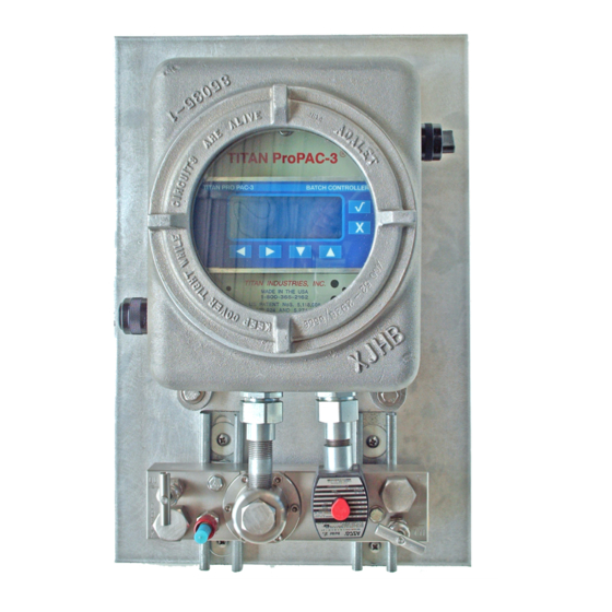
Table of Contents Introduction - pg. 4 Frequently Asked Questions - pg. 5 Section 1 Batch Controller Programming. - pg. 7 Program Menu Definitions - pg. 9 Channel Section - pg. 16 Programming Guide - pg. 17 Section 2 Normal Operations - pg. 20 Single Injector –... - Page 3 Standard Accessories for Pro Pac-3 External Accessories: Explosion Proof Box. On / Off Switch Pro Pac-3 Faceplate Stainless Steel Pro Pac-3 Flow meter w/ Microprocessor gears Push to Test Button Strainer Solenoid Three-way Ball valve Check Two-way valve Ball valve Internal Accessories: Pro Pac-3 Mother Board.
-
Page 4: Introduction
Because the ProPAC-3 has numerous input/output control options and performance features, it is recommended the user contact Titan to discuss the specifics of how the ProPAC-3 may be integrated in an integrated control system in order to achieve user expectations. -
Page 5: Frequently Asked Questions
3. What type of product pulse signals can a Pro Pac-3 accept? Both AC and DC signals. 4. Would I be able to use Titan injector if I do not have product pulses? Yes. You can use Auto PAC. 5. What is the difference between Pro Pac-3, Auto Pac, and MAI? ProPAC3 is a proportional injection controller. - Page 6 10. What is the operating pressure? The maximum operating pressure is 250 psig. The maximum differential pressure is 145 psig. 11. What is the injection volume per cycle? The minimum is 5 cc. The maximum is 685 cc. 12. What is the flow meter accuracy? Up to 0.05% of rate.
-
Page 7: Batch Controller Programming
CONTRAST ADJUSTMENT Note: Use the Up/Down arrows to change the graphical display contrast, if on ProPac-3 power-up the display is difficult to read. Hold down until display is clear. STEP 1 Press the key to ENTER the program. If lock code has been programmed, enter the lock code as instructed. - Page 8 PRESS TO ENTER THE PROGRAMMING MODE On entering the program, the Program Mode screen will appear for four (4) seconds. BATCH CONTROLLER TITAN PRO PAC-3 - Microprocessor Software Version - Unique Microprocessor Serial Number Titan - Number of times the Microprocessor has...
-
Page 9: Program Menu Definitions
(Use with Programming Guide Section 1 pg. 17-19) The following definitions are provided in order to assist the user in properly programming the Titan ProPAC-3 additive injector. The definitions are also provided in order to explain the many product features of the ProPAC-3 additive injector. - Page 10 Programmable Enabled or Disabled. Contact Titan Industries for specific use. Pump Start - An additive pump start output is available on the ProPAC-3. This output is turned on when: the injector is either hardware or software Authorized, the Test Injection Button is pushed or Calibration Mode is entered.
- Page 11 Additive Units - Additive and Product totals may be accumulated in either Gallons or Liters. Calibration Mode - Provides an auto-calibration of the ProPac-3. Programmable Enabled or Disabled. When enabled, the user can enter the auto-calibration mode of the injector by pushing and holding the Test Injection Button for three (3) seconds.
- Page 12 Smith Accuload: 1) Product Pulses with communication verification and alarm shutdown, 2) No Product Pulses, batch injection commands are sent to the injector via the communication link. Call Titan technical support for detail about which mode of operation to use.
- Page 13 Pulse Width Long Average - This average is used to determine the maximum or full flow rate. The ProPAC-3 compares this number with the Short Average to determine if the product flow rate has decreased by the Flush Start % Decrease. Programming the Long Average number too large will have no adverse effect on the performance of the frequency method.
- Page 14 Definitions continued Suggested Settings for Brooks Presets using Frequency Line Flush All Brooks electronic presets send 1:1 product flow signals out in bursts that do not reflect the actual flow rate of the product. Hence averaging of product pulse frequency is a necessity when using the frequency method of line flush with a Brook preset.
- Page 15 This solenoid valve is in addition to the solenoid control valve located on the ProPAC-3 injector. The blocking control valve is controlled by the ProPAC-3 microprocessor and it is opened (energized) when additive/dye injections are prescribed for a product load.
-
Page 16: Channel Section
Product Total will increment 1 gallon for each gallon of product loaded. Note 2: It is recommended to use a 1:1 product pulse or turbine meter pulse as the ProPAC-3 product input pulse so accurate product loads may be documented and accounted for. -
Page 17: Programming Guide
PROGRAMMING GUIDE The following menu selections are programmable in the ProPAC-3 Program Mode, Version 3.01 MENU SECTION RANGE / PROGRAM RECOMMENDED PROGRAM SELECTION SETTING ADMINISTRATION SECTION GRAND ADDITIVE TOTAL 0.0000 - 9999999999.9999 none GRAND PRODUCT TOTAL 0.00 - 99999999999.99 none... - Page 18 PROGRAMMING GUIDE MENU SECTION RANGE / PROGRAM SELECTION RECOMMENDED PROGRAM SETTING ALARM SECTION CONTINUED PERMISSIVE TIMEOUT ERROR Enabled / Disabled Only when using a permissive input FLOW SWITCH FAILED Enabled / Disabled Used only when using flow switch input ADDITIVE PERMISSIVE FAIL Enabled/Disabled Used only with software Authorize CALIBRATION ALARM...
- Page 19 PROGRAMMING GUIDE MENU SECTION RANGE / PROGRAM SELECTION RECOMMENDED PROGRAM SETTING BLOCKING CONTROL VALVE Enabled/Disabled Program Enabled, when blocking control valve is installed and used CHANNEL SECTION 0 - 9999999999.99 None Ch1 PRODUCT TOTAL 0.0001 - 9999.9999 As desired See Section 1 pg. 14 Ch1 PRODUCT K FACTOR 1 - 9999 As desired...
-
Page 20: Normal Operations
2.0 Use as: Single Station Injector - One Rate The ProPAC-3 may be used in its simplest form as previous injectors that are used to inject a single additive at a single injection rate. In this example, the "Authorize" feature is programmed Disabled, and Permissive Inputs are not used. -
Page 21: Single Injector - One Injection Rate
2.2 Single Station Injector - Load State Operation The ProPAC-3 will enter the Load State, on receipt of either of the following: 1. Permissive input signal. (Typically 1:1 DC input pulse) 2. Injection request. (Typically 40:1 AC input pulse) On entering the Load State, the viewed screen will automatically switch from the Idle State screen (Fig. 1) to the Load State screen (Fig. - Page 22 3. Alarms may be cleared by the following three methods: a. External “Push to Test” button provided when depressed Clears Alarms. b. Cycling the ProPAC-3 power OFF to ON. c. RS-485 serial communications protocol command. BATCH CONTROLLER...
-
Page 23: Single Injector - Multiple Injection Rates
If serial communications is established, an infinite number of injection rates are available. When the ProPAC-3 is used as a multiple station injector and wired utilizing the Permissive Input feature, the following is required, as a minimum, in order for the injector to function: 1. - Page 24 3.2 Multiple Station Injector - Screen Cycling Idle BATCH CONTROLLER TITAN PRO PAC-3 State Operation Grand Additive In order to use multiple channels, the Permissive 4,557.4 Input must be programmed with the number of Load Product channels desired for use (1,2, or 3) and the Authorize 9,026,480 feature must be programmed Enable.
- Page 25 Provided the ProPAC-3 is programmed Authorize-Enable, and Permissive Input programmed (1,2, or 3), on receipt of a Permissive Input (rate selection), the ProPAC-3 will enter the Load State for the channel permitted, and the injector will automatically display the appropriate Load Screen.
- Page 26 3.4 Multiple Station Injector - Alarm State Operation As with the single station use of the ProPAC-3, the Alarm State Screen will indicate injector alarms occurring during the Load State. The Alarm State Screen will alternate (5 second intervals) with the channel specific Load State Screen until the alarm has been reset.
-
Page 27: Alarm Operations
Alarms are useful in determining conditions that may adversely affect the desired additive/product ratio. It is important to note, the desired additive/product ratio can only be achieved if the ProPAC-3 is integrated into a control system where product loading is terminated anytime an alarm is activated. - Page 28 The Load Additive total (A 0.00) and the Load Product total (P31) will be displayed on the alarm screen, in addition to the alarm description (No Additive Pulse). Alarm Cycle Screens Fig. 2 BATCH CONTROLLER TITAN PRO PAC-3 A 0.00 Alarm P 31 No Additive Pulse...
-
Page 29: Alarm General Information
It must be emphasized that an alarm notification by itself will not insure additive/product ratio compliance. It is imperative the ProPAC-3 Permissive Output, as well as other I/O's, be integrated into the terminal control system where product loading may be terminated in the event of an injector alarm. The various I/O and programming features available in the ProPAC-3, when properly integrated, are the best means to insure regulatory compliance regarding additive/product ratios. - Page 30 In the event the microprocessor does not count additive pulses from the Titan additive flow meter within 25 seconds of an injection request, the unit will alarm. When the ProPAC-3 is in this alarmed state, further injection attempts are prohibited. The alarm will activate under the following conditions: 1.
- Page 31 Cause: When the microprocessor detects a permissive input and flow switch input, and does not receive a product pulse input within 120 seconds, the unit will alarm. When the ProPAC-3 is in this alarmed state, further injection attempts are prohibited.
- Page 32 Cause: The ProPAC-3 can provide a quarterly Calibration Alarm by utilizing the on board Real Time Clock (RTC). The alarm assists the user in assuring regulatory compliance. When the ProPAC-3 is in this alarmed state, it does not prevent further injection attempts. The alarm is activated when the injector has not been calibrated for a period of three months.
- Page 33 Product under pressure may leak in a reverse direction through the ProPAC-3 additive flow meter, falsely indicating additive flow. Additive installations should always include a ball valve and a check installed on the additive line at the additive injection point.
-
Page 34: Field Calibration Instructions
Test Port and with the additive pump/motor positioned ON, push the Test Injection pushbutton on the side of the ProPAC-3 several times, in order to purge any air from the system. Air in the additive fluid will make injector calibration impossible to perform accurately. -
Page 35: Manuel Calibration
Test Port and with the additive pump/motor positioned ON, push the Test Injection pushbutton on the side of the ProPAC-3 several times, in order to purge any air from the system. Air in the additive fluid will make injector calibration impossible to perform accurately. - Page 36 ProPAC3 Calibration Sheet Location Injector # Date Beginning K-Factor Trial # 1 Trial # 2 Trail # 3 Trial # 4 Test Injection #1 Test Injection #2 Test Injection #3 Test Injection #4 Test Injection #5 Test Injection #6 Test Injection #7 Test Injection #8 Test Injection #9 Test Injection #10...
- Page 37 ProPAC3 Calibration Sheet (Sample) Location Injector # Date Houston, TX 1/1/2001 Beginning K-Factor 2710 Trial # 1 Trial # 2 Trail # 3 Trial # 4 Test Injection #1 45.5 Test Injection #2 44.6 45.5 Test Injection #3 45.5 Test Injection #4 Test Injection #5 45.5 Test Injection #6...
-
Page 38: Product Specifications
Section 5 Product Specifications Version 3.01 PROCESS CONNECTIONS 1/4" INLET / OUTLET / TEST (standard ProPAC-3) ELECTRICAL 120 VAC/60 HZ or 230 VAC/50 HZ. (Auto-range ProPAC-3 POWER capable) (Except solenoid valve) 30 WATTS WITH HEATER - OFF 130 WATTS WITH HEATER - ON... -
Page 40: Field Installation / Illustrations
AC or DC modules. Some output modules may be mechanical. 3. If PAC-3 injectors are being upgraded to the ProPAC-3 model, the existing wiring may have to be replaced if it is too short. The existing PAC-3 Hall effect sensor should be replaced with the short version of the sensor designed for the ProPAC-3. - Page 41 1. Where possible, allow 6" spacing between injector mounting plates. 2. The ProPAC-3 will arrive with the AC power wiring pre-wired by Titan. The 18" leads for AC power is the only wiring provided. No electrical conduit, seal-off, or junction box is provided.
- Page 42 Dye System Considerations The ProPAC-3 incorporates a specially designed output for product line flush situations. Dyed and clear products are to be loaded from the same load arm. The Blocking Control Valve is used to minimize the capillary effect of the dye leaching into the product line after the product line is flushed. The Blocking Control Valve Output contact is closed when the injector is authorized and opened when line flush is initiated.
-
Page 43: Propac-3 Main Circuit Board I/O Configuration
The standard ProPAC-3 injector utilizes input and output modules that are single channel modules (one input or output per module). Some advanced features of the ProPAC-3 require the use of optional dual input and/or dual output modules. Dual modules have either two inputs or two outputs per module location. The B portion of each module can only be accessed when a dual I/O module is installed. - Page 44 I/O Configuration, continued Wire I/O Function Channel Module Location Terminations Polarity Confirmation or Scaled Output Confirmation or Scaled Output (common) Output Module 2 Alarm Output or Pump Start if enabled (common) Alarm Output or Pump Start if enabled Load Permissive or Permissed Permissive Load Permissive or Permissed Permissive (common) Output Module 1 Line Flush Block Valve (common)
- Page 45 Communications Configuration The ProPAC-3 motherboard has several communication jumpers on the upper center section of the board. The following chart defines the jumpers and their functions: Standard Extra Serial Serial Function Port Port Connects a 120 ohm termination resistor across R+ and R- for 4-...
- Page 46 Communications Configuration, continued The ProPAC-3 adheres to standard EIA RS-485 hardware specifications. The RS-485 specification provides for a minimum of 32 driver/receiver pairs to be connected on a communication network with a maximum length of 4,000 feet. The cable of choice for RS-485 applications is shielded two-twisted pair with ground.
- Page 47 Industries. Note: Shielded cable must be used if a DC input module is used. Input 1 module must match the input voltage provided to the injector. ** ProPAC-3 may be special ordered with an AC or DC Output Module. Connector P2 pin 3 (-) and Pin 4 (+) are used for Load Permissive output wiring. Please note polarity considerations.
- Page 48 I/O Configuration (Recommended ) I/O Configuration (Recommended) This Configuration utilizes many of the commonly used ProPAC-3 product features. 1. Connector P4 (AC Power) is pre-wired with 18" leads. This is the only connector with external leads. Shown with bold lines.
- Page 49 *****Connector P7 RS-485. Shielded Belden cable must be used. Note 1: When converting from a PAC-3 to a ProPAC-3. Only the two (2) red wires should be connected to pins 1 and 2 on the Test connector P1. Pins 3 and 4 are used for future purposes. If a lighted pushbutton is installed on the ProPAC-3, disconnect the black and white wires.
-
Page 50: Pro Pac 3 Spare Parts List
Dual Input Module (240 VAC, 30 VDC) 7500 Dual Output Module (240 VAC, 30 VDC) 7501 ProPAC-3 On/Off Switch 3045 ProPAC-3 Push to Test Button 3050 ActionPak7500 4-20mA to Pulse Call Titan Industries at (281)-353-3600 or send an email to sales@titan-solutions.com for price and ordering information. -
Page 51: Easy Basic Troubleshooting Guide
Trouble Shooting Guide for Titan PAC3 and ProPAC3 1. Power is applied to the injector, but the display does not light up. ◆AC wiring incorrect – check power and ground wiring. Check power on other injectors. ◆Auto Switch is in “Off” position – make sure the switch is in “On” position. - Page 52 It is possible the additive flow meter pulse counts from the Titan flow meter are not received by the microprocessor following an injection request. This problem could cause the solenoid to remain energized (open) for an extended period of time in an attempt to complete the injection request. If the microprocessor does not count or detect pulses from the Titan flow meter within 30 seconds of the receipt of a valid injection request, the alarm will activate.
- Page 53 10. Inconsistent calibration. ◆Flow meter gears damaged – inspect and replace gears. ◆Improper calibration check procedure – read Section 4 Field Calibration Instructions. ◆Inconsistent pressure differential during calibration test – make sure the differential does not fluctuate greatly during calibration test 11.
- Page 54 – adjust the Flush Start (% Decrease). 15. Additive Pulse Detection (PAC3) or No Additive Pulse (ProPAC3) is displayed. It is possible the additive flow meter pulse counts from the Titan flow meter are not received by the microprocessor following an injection request.
-
Page 55: Warranty
◆Inconsistent pressure differential during calibration test – make sure the differential does not fluctuate greatly during calibration test. WARRANTY Titan Industries, Inc. warrants its products against defects in material and workmanship, for a period of one (1) year, from the date of shipment to the Buyer. - Page 56 The Warranty is limited to repair or replacement of the defective unit/component, at the option of Titan Industries, Inc. The Warranty is void, if the product has been altered, misused, dismantled, or otherwise abused. Titan Industries, Inc. shall not, in any case, be liable for special, incidental, consequential, indirect, or other similar damages arising from the use of the Titan ProPAC-3 Injector.
Need help?
Do you have a question about the ProPAC-3 and is the answer not in the manual?
Questions and answers