
Subscribe to Our Youtube Channel
Related Manuals for C-TEC EACIE


Summary of Contents for C-TEC EACIE
- Page 1 EACIE EVACUATION ALERT CONTROL AND INDICATING EQUIPMENT (EACIE) 1 to 4 Loop Panel Installation, Maintenance & Programming Manual Approved Document No. DFU5030020 Rev 1...
-
Page 2: Table Of Contents
EACIE Evacuation Alert Control and Indicating Equipment CAUTION ! DO NOT connect or disconnect the panel’s internal wiring / looms, or terminate field wiring at the PCBs, with the panel’s power applied (either mains or battery). Failure to observe this will destroy the panel’s electronic components and the warranty will be void. - Page 3 Figure 2 – Location of EACIE Panel Components ....................9 Figure 3 – Protective Cabinet and EACIE Panel Mounting Location ..............10 Figure 4 – Protective Cabinet Wall Mounting and EACIE Panel Fitting ............. 11 Figure 5 – Typical EAS Loop Overview ......................14 Figure 6 –...
-
Page 4: Important Notes
Installation, Maintenance & Programming manual (this manual) – Explains how to install, commission and maintain the EACIE. This manual MUST NOT be left accessible to the user. User Manual and Log Book (Document No. DFU5030070) – Gives detailed operational information and details about the panel’s indicators and controls. -
Page 5: System Design
Available in 1, 2, or 4 loop models. Up to 48 evacuation alert zones on a single EACIE panel, extendable up to 200 zones on a shared EACIE system. Extendable to a networked system using C-TEC’s CAST ZFP panels. - Page 6 Custom-made ‘slide-in’ labelling system for floor-by-floor or zone-by-zone layouts. EACIE panel housed in a separate protective cabinet which complies with STS 205 complete with a high security EN 1303 locking system. RS232 and RS485 ports - for ancillary devices and graphics interface (maintenance use only) ...
-
Page 7: Typical Eacie Panel Pcb Connections
4 Loop Model Shown. Refer to Appendix 4 for fitting the optional 2-Loop PCB. Figure 1 – Typical EACIE Panel PCB Connections EACIE Status and Switch Panel Connections Page 7 of 38 Approved Document No. DFU5030020 Rev 1 Installation and Programming Manual... -
Page 8: Cabling Requirements
Mains wiring should be standard or enhanced fire-resistant and segregated from extra low voltage field wiring. The general requirement for the 230V, 50Hz mains supply to the EACIE panel is fixed wiring, using 3 core cable (no less than 1mm and no more than 2.5mm... -
Page 9: Installation
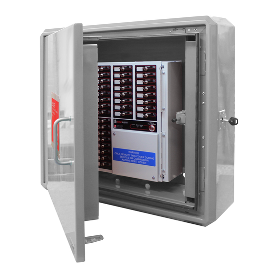
EACIE Panel Description The EACIE panel is mounted inside a separate protective cabinet (not shown below). The panel’s chassis comprises of a hinged steel lid and a steel back box which houses a power supply unit (PSU) and several PCBs, as shown in Figure 2 below. -
Page 10: Mounting Location
The EACIE must be sited at an appropriate location for the Fire and Rescue Service (FRS) responding to a fire within the building. The position should be in close proximity to the normal FRS building entry point. If there is a concierge desk (or similar) the EACIE should be sited behind the desk, providing this location is easily accessible to the FRS. -
Page 11: Wall Mounting The Protective Cabinet And Fitting The Eacie Panel
Note: A fitting template (supplied with the cabinet) may be used in conjunction to the method detailed below. Suggested order of mounting the Protective Cabinet and EACIE Panel (see Figure 4) Ensure you have enough space on the wall by looking at the overall size of the finished EACIE installation on the template drawing. ... -
Page 12: Cable Entry In The Protective Cabinet And Eacie Panel
Route the mains supply cable along the left-hand side of the EACIE chassis to the PSU (see Photo 2). Route the loop cables (and cables to the fault relay – if used) along the right-hand side of the EACIE chassis to the Main Control PCB (see Photo 3). -
Page 13: Inserting The
EACIE Evacuation Alert Control and Indicating Equipment Inserting the ‘slide-in’ labels A customisable ‘slide-in’ label system is employed by the EACIE panel for both the Z41/CA module (for use by an authorised engineer) and the 8 way switch panels (for use by the FRS). -
Page 14: Evacuation Alert System Overview
EACIE Evacuation Alert Control and Indicating Equipment Evacuation Alert System Overview Figure 5 shows a typical evacuation alert system (EAS) loop complete an EACIE panel, sounder controllers & evacuation alert devices. Note: No fire detection equipment, e.g. fire detectors, manual call points, should be connected to the EACIE panel and the EAS must not interface with any other systems or equipment. -
Page 15: Analogue Addressable Loop(S) Wiring
Plug-on 5mm connectors accept up to 2.5mm cable. The loop’s earth screens should be adequately insulated and ONLY terminated at the earth bar in the EACIE’s chassis to ensure earth continuity. Check for loop earth faults and loop crossover faults. -
Page 16: Relay Output Wiring
EACIE Evacuation Alert Control and Indicating Equipment Relay Output Wiring One volt-free relay output connection is provided on the Main PCB - a fail-safe fault output, which switches under any fault condition or total power failure. The relay is capable of switching 1A @ 30Vdc. -
Page 17: Connecting Mains To The Panel's Psu
EACIE Evacuation Alert Control and Indicating Equipment 5.10 Connecting Mains to the Panel’s PSU The PSU is equipment and MUST BE EARTHED. The panel’s PSU is a mains to regulated DC power supply providing 5A @ 24Vdc nominal. Combining the functions of a PSU, battery charging unit and battery monitoring unit, it is fully compliant with EN 54-4/A2. -
Page 18: Connecting The Standby Batteries
YUASA REC22-12I batteries are recommended. The batteries should be connected in series and positioned on the shelf at the top of the EACIE chassis. Connect the ‘Red’ (+ve) and ‘Black’ (-ve) battery wires from the battery terminals to connector block CONN7 on the power supply’s PCB. -
Page 19: Touchscreen, Indicators & Controls
EACIE Evacuation Alert Control and Indicating Equipment 6 TOUCHSCREEN, INDICATORS & CONTROLS Note that information on the EACIE’s front panel toggle switches and indicators (for use by the FRS) can be found in the separate User Manual (Document No. DFU5030070). -
Page 20: Commissioning & Programming
Feed field cables through the rear aperture in the protective cabinet, then route cables through the top aperture in the EACIE panel. Terminate all screens to the earth bar in the EACIE panel’s chassis – see section 5.4. ... -
Page 21: Figure 11 - Access Level 3 Menu Structure
EACIE Evacuation Alert Control and Indicating Equipment Figure 11 – Access Level 3 Menu Structure Page 21 of 38 Approved Document No. DFU5030020 Rev 1 Installation and Programming Manual... -
Page 22: Access Level 3 Menu Structure
EACIE Evacuation Alert Control and Indicating Equipment Access Level 3 Menu Structure Figure 11 shows the menu options available at access level 3. Three ‘access levels’ are available at the panel; general user is access level 1, authorised user is access level 2 and authorised systems engineer is access level 3. -
Page 23: Engineering Functions
EACIE Evacuation Alert Control and Indicating Equipment Engineering Functions The Engineering Functions menu is used to access the panel’s comprehensive test functions and display important system status information. At Access Level 3, press the button and the window shown below left appears. - Page 24 EACIE Evacuation Alert Control and Indicating Equipment When an individual loop device icon is pressed the Device Manager window appears (shown below) allowing the user to perform additional functions, which are listed below. 7.4.1.1 Device Outputs This function allows you to turn ON/OFF the selected device’s outputs.
-
Page 25: Show Psu Status
EACIE Evacuation Alert Control and Indicating Equipment 7.4.1.5 Replace Device This function may be used, for example, to replace a faulty loop device without requiring a new loop learn. When the Replace Device button is pressed, select the loop and device number. Replace the selected loop device, as required. -
Page 26: Find Loop Break
EACIE Evacuation Alert Control and Indicating Equipment 7.4.5 Find Loop Break This function allows you to find and display where a break in the loop exists. When the FIND LOOP BREAK prompt appears select a loop, then press Accept and the panel will initialize both ends of the loop. -
Page 27: Commissioning Functions
Commissioning functions are listed in sections 7.5.1 to 7.5.12. Commissioning Note: All the loop devices connected to the EACIE panel need to have a unique address assigning to them. In addition, the panel needs to read all the loop devices and identify their address by performing a ‘loop learn’. -
Page 28: Loop Learn
EACIE Evacuation Alert Control and Indicating Equipment 7.5.1 Loop Learn During a loop learn, the panel interrogates every device fitted on a selected loop to identify their address and to find out the type of device. This provides the opportunity to identify any missing devices, double-addressed devices, incomplete loops as well as wrong device types. -
Page 29: Fix Address Faults
EACIE Evacuation Alert Control and Indicating Equipment 7.5.3 Fix Address Faults This function helps to locate and fix devices with duplicate (double) addresses and also activates device (polling) LEDs. Typically, a fault may have been displayed at the panel stating ‘Duplicate Address’. -
Page 30: Edit Zone Name
EACIE Evacuation Alert Control and Indicating Equipment 7.5.8 Edit Zone Name This function allows a text description to be assigned to an evacuation alert zone. At Access Level 3 > Commissioning Functions, press the button and a window similar to the one shown below left appears. -
Page 31: Event Log Functions
EACIE Evacuation Alert Control and Indicating Equipment Event Log Functions This function lists, filters and resets the panel’s event or fault log. At Access Level 3, press the button and the window shown below appears: The Show Event Log button, when pressed, lists both the panel’s event and alarm log (up to 9999 events). -
Page 32: Set The Panel's Time And Date
EACIE Evacuation Alert Control and Indicating Equipment Set the Panel’s Time and Date This function is used to set the panel’s time and date which is required for accurate logging of events in the panel’s log. The panel has a real-time 24 hour clock with default time and date settings. An automatic DST (Daylight Saving Time) option is available which will automatically adjust the panel’s clock one hour forward on... -
Page 33: Maintenance
If this recommendation is not implemented, the system is no longer compliant with this British Standard. Note: Maintenance of evacuation alert system equipment external to the EACIE panel will be detailed in the individual instructions supplied with each device. -
Page 34: Appendix 1 - Protective Cabinet And Eacie Panel Dimensions
EACIE Evacuation Alert Control and Indicating Equipment Appendix 1 – Protective Cabinet and EACIE Panel Dimensions All dimensions in mm. Drawings not to scale. Protective Cabinet EACIE Panel Appendix 2 – EACIE Panel Programming Module Control/Display module c/w 4.3” touchscreen, keyswitch, 16 LEDs - Part No. -
Page 35: Appendix 3 - Standby Battery Calculation
EACIE Evacuation Alert Control and Indicating Equipment Appendix 3 – Standby Battery Calculation The standby time of the EACIE panel, after the mains has failed, depends on the quiescent and alarm loading of the panel, and the capacity of the batteries. -
Page 36: Appendix 5 - Eacie Panel Technical Specification
Up to 8 CAST ZFP panels. Max length between nodes = 1km. Max. number of Evacuation Alert Zones: Up to 48 on a standalone EACIE panel. Up to 200 on a shared EACIE panel system. Indicators and Controls User indicators (Switch Module): Next to toggle switches are individual Evacuation LED (Red) &... -
Page 37: Appendix 6 - Glossary Of Terms
Evacuation Alert Device (sounder): Component of the evacuation alert system, not incorporated in the EACIE, which is used to signal to the occupants of a flat that evacuation is required by the FRS. Evacuation Alert Zone: May contain flats, part floors, or a complete floor of a building. - Page 38 EACIE Evacuation Alert Control and Indicating Equipment Installation and Programming Manual Approved Document No. DFU5030020 Rev 1 Page 38 of 38...
Need help?
Do you have a question about the EACIE and is the answer not in the manual?
Questions and answers