Sign In
Upload
Manuals
Brands
C-TEC Manuals
Control Panel
EAP4/24/CA/CHASSIS
C-TEC EAP4/24/CA/CHASSIS Manuals
Manuals and User Guides for C-TEC EAP4/24/CA/CHASSIS. We have
1
C-TEC EAP4/24/CA/CHASSIS manual available for free PDF download: Installation, Maintenance & Operating Manual
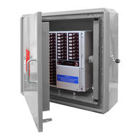
C-TEC EAP4/24/CA/CHASSIS Installation, Maintenance & Operating Manual (38 pages)
EVACUATION ALERT CONTROL AND INDICATING EQUIPMENT
Brand:
C-TEC
| Category:
Control Panel
| Size: 5.94 MB
Table of Contents
Table of Contents
2
1 Important Notes
4
Items Supplied
4
Note:a Glossary of Terms Used in These Instructions Is Listed in Appendix 6.
4
Notices
4
Relevant Eacie Standards
4
2 Eacie Panel Features
5
Equipment Guarantee
5
System Design
5
Figure 1 - Typical EACIE Panel PCB Connections
7
3 Typical Eacie Panel Pcb Connections
7
4 Cabling Requirements
8
Mains Wiring
8
Field Wiring
8
Testing of Field Wiring
8
5 Installation
9
Eacie Panel Description
9
Figure 2 - Location of EACIE Panel Components
9
Mounting Location
10
Figure 3 - Protective Cabinet and EACIE Panel Mounting Location
10
Wall Mounting the Protective Cabinet and Fitting the Eacie Panel
11
Figure 4 - Protective Cabinet Wall Mounting and EACIE Panel Fitting
11
Cable Entry in the Protective Cabinet and Eacie Panel
12
Inserting the
13
Nserting the Slide in Labels
13
Evacuation Alert System Overview
14
Figure 5 - Typical EAS Loop Overview
14
Analogue Addressable Loop(S) Wiring
15
Figure 6 - Analogue Addressable Loop Connections
15
Relay Output Wiring
16
Remote Pc Connection
16
Figure 7 - Relay Output Detail
16
Figure 8 - PC Connection
16
Connecting Mains to the Panel's PSU
17
Figure 9 - 5A PSU Layout and Mains Connection Details
17
Connecting the Standby Batteries
18
Figure 10 - Battery Connection Details
18
6 Touchscreen, Indicators & Controls
19
Removing the Maintenance Cover
19
7 Commissioning & Programming
20
Recommended Shortform Installation & Commissioning Procedure
20
Figure 11 - Access Level 3 Menu Structure
21
Access Level 3 Menu Structure
22
How to Enter Access Level 3 (Al3)
22
Engineering Functions
23
Device Manager
23
Show PSU Status
25
Test Output Group
25
Show Loop Status
25
Find Loop Break
26
Change Access Level 2 (AL2) Code
26
Change Access Level 3 (AL3) Code
26
Show System Details
26
Clean Start
26
Commissioning Functions
27
Loop Learn
28
Auto Address
28
Fix Address Faults
29
Verify Loop
29
Device Manager
29
Add New Device
29
Add/Delete/Edit a Device
29
Edit Zone Name
30
Edit Output Group Name
30
Setup Networking
30
Synchronise Network Data
30
Set Loops Fitted
30
Event Log Functions
31
Set the Panel's Time and Date
32
Show Supervisory Events
32
8 Maintenance
33
Appendix 1 - Protective Cabinet and Eacie Panel Dimensions
34
Appendix 2 - Eacie Panel Programming Module
34
Appendix 3 - Standby Battery Calculation
35
Appendix 4 - Fitting the 2-Loop Pcb (Optional)
35
Appendix 5 - Eacie Panel Technical Specification
36
Appendix 6 - Glossary of Terms
37
Advertisement
Advertisement
Related Products
C-TEC EACIE
C-TEC EAP1/8/CA/CHASSIS
C-TEC EAP2/8/CA/CHASSIS
C-TEC EAP4/16/CA/CHASSIS
C-TEC EAP4/32/CA/CHASSIS
C-TEC EAP4/40/CA/CHASSIS
C-TEC EAP4/48/CA/CHASSIS
C-TEC EAPBOX
C-TEC EP203
C-TEC AlarmSense CFP702-2
C-TEC Categories
Control Panel
Fire Alarms
Power Supply
Controller
Smoke Alarm
More C-TEC Manuals
Login
Sign In
OR
Sign in with Facebook
Sign in with Google
Upload manual
Upload from disk
Upload from URL