Table of Contents
Advertisement
Quick Links
Advertisement
Table of Contents

Subscribe to Our Youtube Channel
Related Manuals for Rohde & Schwarz UP300


Summary of Contents for Rohde & Schwarz UP300
- Page 1 11/2007...
- Page 2 Copyright R&S UP300/350 © Copyright 2007 ROHDE & SCHWARZ GmbH & Co. KG Test and Measurement Division Mühldorfstraße 15 81671 München, Germany 4th edition 11/2007 Printed in Germany. Printed on FFC bleached paper. Subject to alterations. Errors excepted. Reprints, also in extracts, are only allowed with written permission of the manufacturer.
- Page 3 R&S UP300/350 Chapter Overview Chapter Overview General Content of the Manuals for the Audio Analyzer R&S UP300/350 Data Sheet Safety Instructions Certificate of Quality EC Certificate of Conformity Support Center Addresses List of Rohde & Schwarz Offices Chapter 1 Introduction...
- Page 4 Putting into operation Basic operating procedures and control elements Operation via menus In the introduction, a typical R&S UP300/350 measurement is described. The operating manual also contains information about maintenance and troubleshooting based on the warnings and error messages issued by the instrument.
-
Page 5: Table Of Contents
EC Certificate of Conformity ......................1-32 Support Center Address....................... 1-33 List of Rohde & Schwarz Offices....................1-34 Introduction....................1-35 1.1 Application Range of the R&S UP300/350 ................1-35 1.2 Supplied Accessories ......................1-36 1.3 Warranty ..........................1-36 Control Elements ..................2-37 2.1 Front View .......................... -
Page 6: Table Of Contents
Table of Contents R&S UP300/350 3.2 Setting up the Instrument ..................... 3-40 3.3 Connecting the R&S UP300/350 to the AC Line ..............3-42 3.4 Switching On the R&S UP300/350 ..................3-42 3.5 Function Test ......................... 3-43 3.6 EMC ............................3-43 3.7 Connecting a DUT........................ - Page 7 SERVICE Menu ................5-88 5.6.4.6 INFO Menu..................5-88 5.6.4.7 CALIB Menu ..................5-88 Working with the R&S UP300/350.............. 6-89 6.1 Factory Default Settings ....................... 6-89 6.1.1 Generator........................6-90 6.1.2 Analyzer ........................6-94 6.1.3 Graph ........................... 6-97 6.1.4 System ......................... 6-97 6.2 Generator..........................
- Page 8 Table of Contents R&S UP300/350 6.2.1.2.1 Selecting the Generator Bandwidth ..........6-102 6.2.1.2.2 Selecting the Reference Potential of the Output Signal....6-103 6.2.1.2.3 Activating/Deactivating the Generator Output ........ 6-104 6.2.1.2.4 Selecting the Type of the Level Range Switchover ......6-105 6.2.1.3...
- Page 9 R&S UP300/350 Table of Contents 6.3.3 Configuring the Filters (FILTER)................6-282 6.3.3.1 Selecting the Filters................. 6-283 6.3.4 Starting and Stopping the Measurements ..............6-285 6.4 Graph Menu.......................... 6-286 6.4.1 Selecting the Display Mode (GRAPH MODE) ............6-287 6.4.1.1 Selecting the Display Parameters........... 6-288 6.4.1.2...
- Page 10 Starting the Auto Adjustment of the Generator Module ....6-342 6.5.7.2 Starting the Auto Adjustment of the Analyzer Module ....6-342 6.5.7.3 Starting the Auto Adjustment of the R&S UP300/350..... 6-343 Instrument Interfaces ................7-344 7.1 Keyboard Connector (KEYB)....................7-344 7.2 Monitor Connector (MON)....................7-344 7.3 Reference Input and Output (10 MHz In/Out)..............
-
Page 11: Data Sheet
R&S UP300/350 Data Sheet Data Sheet Note: In a highly innovative company like Rohde & Schwarz, products are continuously undergoing further development. To obtain information about applications features, visit Internet page http://www.smart.rohde-schwarz.com. Analyzer Analog audio inputs Frequency range DC/10 Hz to 80 kHz 10 Hz to 20 Hz ±0.1 dB... -
Page 12: Measurement Functions
Data Sheet R&S UP300/350 Format professional and consumer Measurement functions RMS value, wideband Error limits measurement speed AUTO, at ±0.1 dB, additional error with 1 kHz sine, AC coupling DC coupling measurement speed AUTO ±0.1 % of measurement range FAST ±0.1 dB additional error... - Page 13 R&S UP300/350 Data Sheet DC voltage Voltage range 0 V to ±33 V Error limits ± (1 % of measured value + 0.5 % of measurement range) Total harmonic distortion (THD) Fundamental 20 Hz to 20 kHz Frequency tuning fixed through entered value,...
-
Page 14: Filters
Data Sheet R&S UP300/350 Spectrum bar graph showing signal and distortion Modulation distortion (MOD DIST) Frequency range lower frequency 30 Hz to 2.7 kHz upper frequency 8 × f to 20 kHz lower Error limits ±0.5 dB Inherent distortion = 60 Hz, <... -
Page 15: Fft Analyzer
R&S UP300/350 Data Sheet FFT analyzer Frequency range DC to 80 kHz FFT size 1 k, 2 k, 4 k, 8 k, 16 k points Window functions rectangular, Hann, Blackman- Harris, Rife-Vincent 1 to 3, Hamming, flat top, Kaiser (β = 12) - Page 16 Data Sheet R&S UP300/350 Sine Frequency range 2 Hz to 80 kHz Error limits at 1 kHz ±0.1 dB Frequency response (ref. to 1 kHz) 20 Hz to 20 kHz ±0.05 dB Inherent distortion THD+N measurement bandwidth 20 Hz < -90 dB...
-
Page 17: Sweep
R&S UP300/350 Data Sheet SINE BURST signal 1.2 kHz ON-TIME 1 cycle INTERVAL 2 cycles Sweep Generator function Sine Sweep parameters frequency and/or level Sweep spacing linear, logarithmic Sweep Modes Single, continuous Coupled analyzer functions RMS; RMS Sel.; THD(N) Sweep Points... -
Page 18: Digital Audio Protocol (Model R&S Up350 Only)
Data Sheet R&S UP300/350 Output current < 20 mA Source impedance 10 Ω, short-circuit-proof Recommended headphone 600 Ω impedance Digital audio protocol (model R&S UP350 only) Generator Validity bit NONE, L+R Channel status data predefined masks for professional or consumer format in acc. - Page 19 R&S UP300/350 Data Sheet Ambient conditions Operating temperature range meets EN 60068-2-1/2 +5 °C to +45 °C Storage temperature range -20 °C to +70 °C Relative humidity meets EN 60068-2-78 95 % at +40 °C (non-condensing) Mechanical resistance Sinusoidal vibration...
- Page 20 R&S UP300/350 E-1147.2759.00 1-20 Operating Manual, 11/2007...
-
Page 21: Safety Instructions
Before putting the product into operation for the first time, make sure to read the following S a f e t y I n s t r u c t i o n s All plants and locations of the Rohde & Schwarz group of companies make every effort to keep the safety standard of our products up to date and to offer our customers the highest possible degree of safety. - Page 22 Safety Instructions Observing the safety instructions will help prevent personal injury or damage of any kind caused by dangerous situations. Therefore, carefully read through and adhere to the following safety instructions before putting the product into operation. It is also absolutely essential to observe the additional safety instructions on personal safety that appear in relevant parts of the product documentation.
- Page 23 Safety Instructions 4. If products/components are mechanically product itself is not permitted. Doing so can and/or thermically processed in a manner result in the danger of an electric shock that goes beyond their intended use, from the product. If extension cords or hazardous substances (heavy-metal dust connector strips are implemented, they such as lead, beryllium, nickel) may be...
- Page 24 Safety Instructions 19. If a product is to be permanently installed, the battery or storage battery only with the the connection between the PE terminal on matching Rohde & Schwarz type (see site and the product's PE conductor must spare parts list). Batteries and storage be made first before any other connection batteries must be recycled and kept is made.
- Page 25 Informaciones de seguridad Por favor lea imprescindiblemente antes de la primera puesta en funcionamiento las siguientes Informaciones de seguridad El principio del grupo de empresas Rohde & Schwarz consiste en tener nuestros productos siempre al día con los estandards de seguridad y de ofrecer a nuestros clientes el máximo grado de seguridad. Nuestros productos y todos los equipos adicionales son siempre fabricados y examinados según las normas de seguridad vigentes.
- Page 26 Informaciones de seguridad Tener en cuenta las informaciones de seguridad sirve para tratar de evitar daños y peligros de toda clase. Es necesario de que se lean las siguientes informaciones de seguridad concienzudamente y se tengan en cuenta debidamente antes de la puesta en funcionamiento del producto. También deberán ser tenidas en cuenta las informaciones para la protección de personas que encontrarán en el capítulo correspondiente de la documentación de producto y que también son obligatorias de seguir.
- Page 27 Informaciones de seguridad 3. Como en todo producto de fabricación comprometido a valorar y señalar areas de industrial no puede ser excluido en general trabajo en las que se corra un riesgo de que se produzcan al usarlo elementos aumentado de exposición a radiaciones para que puedan generar alergias, los llamados evitar riesgos.
- Page 28 Informaciones de seguridad 12. No utilice nunca el producto si está dañado el 20. En caso de que los productos que son cable eléctrico. Compruebe regularmente el instalados fijamente en un lugar sean sin correcto estado de los cables de conexión a protector implementado, autointerruptor o red.
- Page 29 Informaciones de seguridad 27. Baterías y acumuladores no deben de ser 31. Las asas instaladas en los productos sirven expuestos a temperaturas altas o al fuego. solamente de ayuda para el manejo que Guardar baterías y acumuladores fuera del solamente está previsto para personas. Por alcance de los niños.
-
Page 31: Certificate Of Quality
Certified Quality System DIN EN ISO 9001 : 2000 DIN EN 9100 : 2003 DIN EN ISO 14001 : 2004 DQS REG. NO 001954 QM UM QUALITÄTSZERTIFIKAT CERTIFICATE OF QUALITY CERTIFICAT DE QUALITÉ Sehr geehrter Kunde, Dear Customer, Cher Client, Sie haben sich für den Kauf eines you have decided to buy a Rohde &... -
Page 32: Ec Certificate Of Conformity
EC Certificate of Conformity Certificate No.: 2005-33 This is to certify that: Equipment type Stock No. Designation UP300 1147.2497.03 Audio Analyzer UP350 1147.2507.03 Audio Analyzer complies with the provisions of the Directive of the Council of the European Union on the... - Page 33 Customer Support Technical support – where and when you need it For quick, expert help with any Rohde & Schwarz equipment, contact one of our Customer Support Centers. A team of highly qualified engineers provides telephone support and will work with you to find a solution to your query on any aspect of the operation, programming or applications of Rohde &...
- Page 34 Address List Headquarters, Plants and Subsidiaries Locations Worldwide Headquarters Please refer to our homepage: www.rohde-schwarz.com ◆ Sales Locations ROHDE&SCHWARZ GmbH & Co. KG Phone +49 (89) 41 29-0 Mühldorfstraße 15 · D-81671 München Fax +49 (89) 41 29-121 64 ◆ Service Locations P.O.Box 80 14 69 ·...
-
Page 35: Introduction
Application Range of the R&S UP300/350 Introduction This chapter Chapter 1 describes the use of the R&S UP300/350, provides information on functions and supplies tips regarding storage and transportation procedures. Furthermore, you will find a description on how to proceed in warranty cases. -
Page 36: Supplied Accessories
If your warranty has expired, we will, of course, repair your R&S UP300/350 in accordance with our general installation and service conditions. E-1147.2759.00... -
Page 37: Control Elements
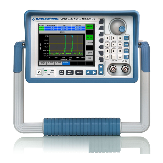
R&S UP300/350 Front View Control Elements Front View ON/STANDBY switch Signal output Ch 1 (BNC connector) ON/STANDBY indicator Signal input Ch 1 (BNC connector) BACK/SYS key Main menu selection keys ESC/CANCEL key Rotary knob ENTER key Numeric keys Cursor keys 3 / 4... -
Page 38: Rear View: R&S Up300/350
Rear View: R&S UP300/350 R&S UP300/350 Rear View: R&S UP300/350 Audio monitoring output (jack) Connector for external keyboard Connector for external USB host Input/output for external reference (10 MHz) Connector for external USB device Reserved AC supply connector Reserved AC line fuse... -
Page 39: Rear View: R&S Up350 (Digital Interface)
R&S UP300/350 Rear View: R&S UP350 (Digital Interface) Rear View: R&S UP350 (Digital Interface) Reserved Digital input S/P DIF Reserved Reserved Input/output for external reference Optical input TOSLINK (10 MHz) Optical output TOSLINK Digital output S/P DIF Operating Manual, 11/2007 2-39 E-1147.2759.00... -
Page 40: Putting The R&S Up300/350 Into Operation
Always be careful not to injure your fingers when installing the instrument and adjusting its handles. The R&S UP300/350 must be only assembled on a firm, level surface. The Setup instructions instrument has a carrying handle which is also used for various setup options. - Page 41 R&S UP300/350 Setting up the Instrument Setting the handle Place the thumb and two fingers around the side-mounted setting lever and loosen it with a turning action. Slide the handle lengthwise while twisting it radially in steps of about 12°.
-
Page 42: Connecting The R&S Up300/350 To The Ac Line
After switching on by means of the AC line switch [20] at the rear panel, the switch on the R&S UP300/350 is in standby mode and the yellow LED [2] comes on. If you front panel press the ON/STANDBY switch [1], the instrument is switched on and the green LED [2] comes on. -
Page 43: Function Test
Function Test Function Test ATTENTION The R&S UP300/350 does not contain any parts the operator can repair. Only properly qualified technicians are allowed to repair the instrument. When performing service procedures, follow the requirements of VDE 0701. After the R&S UP300/350 has been switched on (... -
Page 44: Connecting A Dut
Via the analyzer inputs Ch 1 [9] and Ch 2 [26], you can measure and evaluate the output signals of your DUT ( 6-212). Audio analysis with By combining the generator and the analyzer, the R&S UP300/350 provides versatile capabilities for audio analysis ( 6-259, 6-267, 6-268, 6-272, 6-275). the R&S UP300/350 E-1147.2759.00... -
Page 45: Connecting An External Keyboard
Connecting an External Keyboard ATTENTION Connect the keyboard only when the R&S UP300/350 is off or in the STANDBY mode, otherwise malfunctions may occur at a later time. You can connect an external PC keyboard via the 6-pin PS/2 KEYB connector [22] on the R&S UP300/350’s rear panel. -
Page 46: Connecting A Usb Stick
Connecting a USB Stick ATTENTION To ensure that the USB stick is detected by the R&S UP300/350, the stick must be formatted in the FAT32 file system. You can connect an external USB stick to the USB device interface [17] at the rear of the R&S UP300/350. -
Page 47: Getting Started
The layout of the screen information and the information displayed on the screen are also described. Chapter 6 describes all the R&S UP300/350‘s menus and the associated functions in detail. Generator and Analyzer Settings... - Page 48 Generator and Analyzer Settings R&S UP300/350 Set the signal frequency to 960 Hz in Ch 1 and to 2 kHz in Ch 2. • Press the numeric key to select the channel Ch 1. • Press the key. • Use the numeric keys to enter the value.
- Page 49 R&S UP300/350 Generator and Analyzer Settings Graphical display Graphical display of the measurement results. • Press the main menu selection key. • Using the cursor keys select from the bottom menu bar. • Press the key. • Use the to select the Spectrum setting.
- Page 50 Generator and Analyzer Settings R&S UP300/350 Position the cursor 1 on trace 2. • Using the cursor keys select from the bottom menu bar. • Press the numeric key to select the channel Ch 2. • Press the key. • Press the key to switch on the cursor.
-
Page 51: Manual Operating Concept
R&S UP300/350 Manual Operating Concept This chapter Chapter 5 contains an overview of the R&S UP300/350's basic manual operating concept. This includes a description of the keypad, screen layout, menu operation, and how to set parameters. There is an overview of the menus and functions at the end of this chapter. -
Page 52: Overview Of Operating Steps
Overview of Operating Steps R&S UP300/350 Overview of Operating Steps First hierarchical The R&S UP300/350 is basically operated via hierarchically arranged menus. The following four main menus are simultaneously available at the first level hierarchical level: Analyzer Generator Graph System Using the four keys ANL, GEN, GRAPH, and SYS, you can switch between these menus. -
Page 53: Making Entries From The Keypad
Enter a parameter value by using the numeric keypad, rotary knob, or vertical cursor keys. Making Entries from the Keypad Introduction The R&S UP300/350 is operated using menus in conjunction with a keypad and a rotary knob. The keypad comprises the following sections: Numeric keys [12] Main menu selection keys [10]... -
Page 54: Numeric Keys
Making Entries from the Keypad R&S UP300/350 5.2.1 Numeric Keys Function 1 When the entry field is open, the numeric keys are used to enter numeric parameters. − Inserts one of the digits “0” to “9” at the cursor position. -
Page 55: Rotary Knob
R&S UP300/350 Making Entries from the Keypad 5.2.3 Rotary Knob Function As well as the numeric keys and the cursor keys, the rotary knob is also used to set parameters. The rotary knob has several functions: − Incrementing (turn clockwise) -
Page 56: Action Keys
− This key is for closing the entry field or selection field after data has been entered. The new value is set in the R&S UP300/350. Note: Pressing a unit key will also terminate the entry of the setting data. -
Page 57: Screen Display
R&S UP300/350 Screen Display Screen Display Introduction The screen [14] provides on-going information about events and the parameters associated with the selected setting functions. The display mode for the parameters, lettering of the function keys, and type of menu, all depend on the current settings. -
Page 58: Display Area
Display Area Introduction The display window of the R&S UP300/350 changes depending on the selected main menu. In the Analyzer and Generator menus, the currently set values are displayed in the form of a list. If you select the Graph menu, a measurement diagram is displayed in the parameter field. - Page 59 R&S UP300/350 Screen Display Graph menu (call with Full screen (call with Operating Manual, 11/2007 5-59 E-1147.2759.00...
-
Page 60: Menu Area
Screen Display R&S UP300/350 5.3.2 Menu Area Menu display Menus setting setting parameters functions displayed in the menu area. The selected menu is highlighted, e. g. Genera- tor menu. 5.3.3 Function Area When a menu is selected, the associated instrument functions are displayed Displaying the in the function area. -
Page 61: Calling And Changing The Menus
Calling and Changing the Menus Calling and Changing the Menus Introduction Operating the R&S UP300/350 is menu-guided. The instrument settings associated with any menu you select are displayed in the function area. Pressing a function key has one of the following effects:... - Page 62 Calling and Changing the Menus R&S UP300/350 Note: A function key with a double arrow, e. g. , tells you that pressing this key will call a submenu. Calling/Quitting Press the function key in the menu. submenus The AVERAGING submenu opens and the new functions are assigned to the function keys [13].
-
Page 63: Setting The Parameters
R&S UP300/350 Setting the Parameters Setting the Parameters Choice Parameters can be set in a number of ways: of methods Direct selection of an instrument function (function key) Toggling a setting Selecting settings from selection fields Entering numerical parameters in entry fields... -
Page 64: Selecting Settings
Setting the Parameters R&S UP300/350 5.5.3 Selecting Settings Introduction When you select a menu, a number of instrument functions are displayed in the function area. If certain function keys are then pressed, a selection field is displayed in the diagram area. You can then choose and activate any of the settings offered for selection. -
Page 65: Entering Numerical Parameters
R&S UP300/350 Setting the Parameters 5.5.4 Entering Numerical Parameters Introduction When you select a menu, a number of instrument functions will be displayed in the function area. If you press certain function keys, an entry field will be displayed in the menu area. - Page 66 Terminating a) Press the function key to terminate the entry. entries The R&S UP300/350 sets the value that has been set numerically using the new unit. The entry window is closed. b) Press the key [5] to terminate the entry.
-
Page 67: Entry With The Cursor Keys And Rotary Knob
R&S UP300/350 Setting the Parameters 5.5.4.2 Entry with the Cursor Keys and Rotary Knob Example: Press the main menu selection key. Entering a signal frequency Select the menu with the 3 or 4 cursor keys [6]. 6-115) Press the function key in the menu. - Page 68 Press the key [5] to terminate the entry. The R&S UP300/350 sets the value that has been set numerically but with the old unit. The entry window is closed. Note: If a parameter is unitless or always has the same unit, you can set and terminate the entry only with the ENTER key.
-
Page 69: Overview Of All Menus And Functions
R&S UP300/350 Overview of all Menus and Functions Overview of all Menus and Functions 5.6.1 Generator 5.6.1.1 FUNCTIONS Menu Function key assignment Display the next set of functions. Sinewave signal 6-114) Noise signal 6-119) Multi-sinewave signal 6-122) Sine burst signal... -
Page 70: Noise Menu
Overview of all Menus and Functions R&S UP300/350 Enter the phase difference between the channels. 6-116) Enter the signal amplitude. 6-117) Enter the reference value. 6-118) 5.6.1.3 NOISE Menu Function key assignment Select the amplitude distribution function. 6-120) Enter the signal amplitude. -
Page 71: Sine Burst Menu
R&S UP300/350 Overview of all Menus and Functions 5.6.1.5 SINE BURST Menu Function key assignment Enter the signal frequency. 6-133) Enter the high-level time. 6-134) Enter the interval time. 6-135) Enter the high-level amplitude. 6-136) Enter the low-level amplitude. 6-137) Enter the reference value. -
Page 72: Polarity Test Menu
Overview of all Menus and Functions R&S UP300/350 Enter the reference value. 6-118) 5.6.1.8 POLARITY TEST Menu Function key assignment Enter the signal amplitude. 6-151) Enter the reference value. 6-118) 5.6.1.9 DC OFFSET Menu Function key assignment Enter the DC offset. -
Page 73: Sweep Rms Menu
R&S UP300/350 Overview of all Menus and Functions 5.6.1.10 SWEEP RMS Menu Function key assignment Select the sweep mode. 6-156) Set the measurement time. 6-157) Open the submenu: Set the sweep parameters for frequency. Exit the submenu. Enter the start value. -
Page 74: Sweep Rms Selective Menu
Overview of all Menus and Functions R&S UP300/350 5.6.1.11 SWEEP RMS SELECTIVE Menu Function key assignment Select the sweep mode. 6-156) Select the measurement bandwidth. 6-174) Open the submenu: Set the sweep parameters for frequency. Exit the submenu. Enter the start value. -
Page 75: Sweep Thd Menu
R&S UP300/350 Overview of all Menus and Functions 5.6.1.12 SWEEP THD Menu Function key assignment Select the sweep mode. 6-192) Select the measurement mode. 6-193) Set the measurement time. 6-195) Open the submenu: Set the sweep parameters for frequency. Exit the submenu. -
Page 76: Monitor Menu
Overview of all Menus and Functions R&S UP300/350 5.6.1.13 MONITOR Menu Function key assignment Switch the audio monitoring output on/off. 6-210) Select the signal source. 6-211) Enter the volume. 6-211) 5.6.1.14 CONFIG Menu Function key assignment Select the generator type (digital) (R&S UP350 only). -
Page 77: Analyzer
R&S UP300/350 Overview of all Menus and Functions 5.6.2 Analyzer 5.6.2.1 FUNCTIONS Menu Function key assignment Display the next set of functions. Measure the frequency, DC voltage, and RMS. 6-228) Measure the peak value. 6-237) Measure the quasi-peak value. 6-243) -
Page 78: Frequency, Dc, Rms Menu
Overview of all Menus and Functions R&S UP300/350 5.6.2.2 FREQUENCY, DC, RMS Menu Function key assignment Select the measurement time. 6-230) Select the measurement result display. 6-232) (RMS & FREQ, or RMS & DC) Activate/Deactivate the filter. 6-232) Open the submenu: Set the averaging mode. -
Page 79: Quasi Peak Menu
R&S UP300/350 Overview of all Menus and Functions 5.6.2.4 QUASI PEAK Menu Function key assignment Select the interval time. 6-245) Activate/Deactivate the filter. 6-232) Select the unit for the level display. 6-241) 5.6.2.5 RMS SELECTIVE Menu Function key assignment Select the tuning mode. -
Page 80: Fft Menu
Overview of all Menus and Functions R&S UP300/350 5.6.2.6 FFT Menu Function key assignment Set the FFT size. 6-253) Set the FFT window. 6-253) Activate/Deactivate the filter. 6-232) Open the submenu: Set the averaging mode. Exit the submenu. Activate/Deactivate the averaging. -
Page 81: Dfd Menu
R&S UP300/350 Overview of all Menus and Functions 5.6.2.8 DFD Menu Function key assignment Select the difference frequency distortions 6-271) and measurement standard. Activate/Deactivate the filter. 6-232) Open the submenu: Set the POST FFT. Exit the submenu. Activate/Deactivate the FFT. -
Page 82: Mod Dist Menu
Overview of all Menus and Functions R&S UP300/350 5.6.2.10 MOD DIST Menu Function key assignment ActivateDeactivate the filter. 6-232) Open the submenu: Set the POST FFT. Exit the submenu. Activate/Deactivate the FFT. 6-266) Set the FFT size. 6-253) Set the FFT window. -
Page 83: Filter Menu
R&S UP300/350 Overview of all Menus and Functions 5.6.2.13 FILTER Menu Function key assignment Select filter 1. 6-283) Select filter 2. 6-283) Select filter 3. 6-283) 5.6.2.14 CONFIG Menu Function key assignment Select the analyzer type (digital). 6-215) Select the bandwidth of the analyzer. -
Page 84: Graph Menu
Overview of all Menus and Functions R&S UP300/350 5.6.3 Graph Menu 5.6.3.1 GRAPH MODE Menu Function key assignment Select the display parameters. 6-287) Select the display mode. 6-290) 5.6.3.2 X AXIS Menu Function key assignment Activate automatic display area scaling. -
Page 85: Cursors Menu
R&S UP300/350 Overview of all Menus and Functions 5.6.3.4 CURSORS Menu Function key assignment Open the submenu: Configure cursor 1 on the X axis. Exit the submenu. Activate/Deactivate the cursor. 6-302) Position the cursor manually. 6-305) Assign a cursor to a trace (Ch 1 or Ch 2). - Page 86 Overview of all Menus and Functions R&S UP300/350 Open the submenu: Configure cursor 2 on the Y axis. Exit the submenu. Activate/Deactivate the cursor. 6-310) Position the cursor manually. 6-311) Zoom the display area. 6-312) E-1147.2759.00 5-86 Operating Manual, 11/2007...
-
Page 87: System Menu (Sys Menu)
R&S UP300/350 Overview of all Menus and Functions 5.6.4 System menu (SYS Menu) 5.6.4.1 PRESET Menu Function key assignment Call the instrument setting. 6-318) Select the instrument setting. 6-318) Start the remote control manually. 6-319) 5.6.4.2 STATE Menu Function key assignment Configuration settings of the analyzer and generator. -
Page 88: Config Menu
Overview of all Menus and Functions R&S UP300/350 5.6.4.4 CONFIG Menu Function key assignment Set the date and time. 6-329) Select an internal or external reference source. 6-331) Configure the instrument interfaces. 6-332) Set the screen saver mode. 6-334) Select an internal or external monitor. -
Page 89: Working With The R&S Up300/350
R&S UP300/350 Factory Default Settings Working with the R&S UP300/350 This chapter Chapter 6 fully explains all the functions of the audio analyzer, and the application of these functions. The menus are described in the same sequence as the procedure for configuring and producing an output signal:... -
Page 90: Generator
Factory Default Settings R&S UP300/350 6.1.1 Generator Note: All level parameters of the individual generator functions as well as the frequency at SINE can be set channel independently (Ch 1, Ch 2). These parameters are listed in two columns in the table below the “Settings”. The function parameters applying to both channels (Ch 1&2) are listed in one... - Page 91 R&S UP300/350 Factory Default Settings Function Parameter Settings Channel Ch 1 Channel Ch 2 REF. VALUE 1 mV 1 mV UPPER FREQ 8.100 kHz MEAN FREQ 8.000 kHz DIFF FREQ 200 Hz TOTAL RMS 100 mV (0.1 FS) 100 mV (0.1 FS) REF.
- Page 92 Factory Default Settings R&S UP300/350 Function Parameter Settings Channel Ch 1 Channel Ch 2 FILTER UNIT V (FS) REF. VALUE 1 mV PARAM FREQ START 10 Hz STOP 22.139 kHz POINTS STEP SIZE 223.470 Hz SPACING Linear MEAS DELAY PARAM AMPL START 100 mV (0.1 FS)
- Page 93 R&S UP300/350 Factory Default Settings Function Parameter Settings Channel Ch 1 Channel Ch 2 STEP SIZE 74.7 mV (0.0998) SPACING Linear MEAS DELAY 200 ms OUTPUT MONITOR SOURCE Generator VOLUME 20 % 20 % CONFIG ANALOG BANDWIDTH 22 kHz COMMON...
-
Page 94: Analyzer
Factory Default Settings R&S UP300/350 6.1.2 Analyzer Note: Some parameters of the analyzer functions (FILTER, CONFIG) can be set channel independently (Ch 1, Ch 2). These parameters are listed in two columns in the table below the “Settings”. The function parameters applying to both channels (Ch 1&2) are listed in one column. - Page 95 R&S UP300/350 Factory Default Settings Function Parameter Settings Channel Ch 1 Channel Ch 2 FILTER POST FFT FFT SIZE 1024 WINDOW TYPE Rife Vincent 2 UNIT Ch1 V (FS) UNIT Ch2 V (FS) REF. VALUE Ch1 1 mV (0.001 FS) REF.
- Page 96 Factory Default Settings R&S UP300/350 Function Parameter Settings Channel Ch 1 Channel Ch 2 PHASE MEAS MODE Auto tuning FREQ 1 kHz MOD DIST FILTER POST FFT FFT SIZE 1024 WINDOW TYPE Rife Vincent 2 UNIT PROTOCOL MEAS TIME 100 ms...
-
Page 97: Graph
R&S UP300/350 Factory Default Settings 6.1.3 Graph Function Parameter Settings GRAPH MODE GRAPH TYPE Spectrum GRAPH MODE Overwrite X AXIS AUTO SCALING (MAX,MIN,LOG) AUTO SCALING Y AXIS (MAX,MIN,LOG) CURSORS X1, X2, STATUS POSITION LOCK TO Ch1&2 PLOT ZOOM FIND Y1,Y2... -
Page 98: Generator
Generator R&S UP300/350 Generator Introduction The generator is used to generate all the signals required for the audio measurements. These signal functions can be generated in an analog or digital form (R&S UP350 only). Acoustic analysis of the output signal is pos- sible at the audio monitoring output. -
Page 99: Configuring Generator Parameters (Config)
R&S UP300/350 Generator 6.2.1 Configuring Generator Parameters (CONFIG) Description The CONFIG menu is used for basic configuration of the generator. The following settings are made in the CONFIG menu: Switchover between the analog and digital generator (R&S UP350 only) Configuration of parameters for digital interface (R&S UP350 only) - Page 100 Generator R&S UP300/350 Digital generator (R&S UP350 only) Function key assignment Select the generator type (analog). 6-101) Select the sample frequency of the output signal. 6-107) Enter the sample frequency offset. 6-108) Set the validity bit. 6-108) Select the valid number of bits in the input signal.
-
Page 101: Selecting The Generator Type - Analog/Digital (R&S Up350 Only)
R&S UP300/350 Generator 6.2.1.1 Selecting the Generator Type – Analog/Digital (R&S UP350 only) Introductions The analog generator and the digital generator have separate parameter sets. When the generator type is changed, the new generator with the currently selected measurement functions and the stored parameters of the old generator type is started. -
Page 102: Analog Generator
The R&S UP300/350 provides the following bandwidths for the analog generator: 22 kHz 40 kHz 80 kHz Note: The setting is always valid for both channels (Ch 1&2). -
Page 103: Selecting The Reference Potential Of The Output Signal
R&S UP300/350 Generator 6.2.1.2.2 Selecting the Reference Potential of the Output Signal To prevent hum pick-up caused by grounding loops, the test setup must not have multiple grounding points. Instead, only one point of the test setup should be connected to the housing ground. Depending on the application,... -
Page 104: Activating/Deactivating The Generator Output
Generator R&S UP300/350 6.2.1.2.3 Activating/Deactivating the Generator Output To make the output signal with all configured functions and parameters available at the output, you must first switch on the generator output. Selecting Press the numeric keys 1, 2, or 3 to select channel Ch 1, Ch 2, or both the channel channels Ch 1&2. -
Page 105: Selecting The Type Of The Level Range Switchover
R&S UP300/350 Generator 6.2.1.2.4 Selecting the Type of the Level Range Switchover By selecting the level range switching mode, you determine how the output voltage is to be adjusted at the output amplifier of the generator: Auto The internal signal paths are optimally driven; the output voltage is always adjusted using the attenuators. - Page 106 Generator R&S UP300/350 Entering the After you have selected the “Fixed” level setting, an entry field with the current level range pops up. The default setting is “7.071 V“. At the same level range time, the function keys are assigned various units of measurement.
-
Page 107: Digital Generator (R&S Up350 Only)
R&S UP300/350 Generator 6.2.1.3 Digital Generator (R&S UP350 only) 6.2.1.3.1 Selecting the Sample Frequency of the Output Signal The sample frequencies for digital audio interfaces are standardized. When you select a sample frequency, all of the parameters in the digital generator are adapted to this frequency. -
Page 108: Entering The Sample Frequency Offset
Generator R&S UP300/350 6.2.1.3.2 Entering the Sample Frequency Offset Using the Rate Offset parameter, you can shift the sample frequency in relation to the nominal value. Note: The setting is always valid for both channels (Ch 1&2). Entering the Press the function key in the menu. -
Page 109: Selecting The Valid Number Of Bits In The Output Signal
R&S UP300/350 Generator 6.2.1.3.4 Selecting the Valid Number of Bits in the Output Signal Use the word size to determine the resolution of the output signal. You can generate word sizes between 16 and 24 bits. Selecting Press the numeric keys 1, 2, or 3 to select channel Ch 1, Ch 2, or both the channel channels Ch 1&2. -
Page 110: Setting The Generator Signal Type (Functions)
Generator R&S UP300/350 6.2.2 Setting the Generator Signal Type (FUNCTIONS) Description In the FUNCTIONS menu, you can select the generator signal. The selected function is displayed in a vacant field in the menu bar and is available as a menu key to allow you modifying the function parameters. At the same time, the appropriate function is activated in the generator. - Page 111 R&S UP300/350 Generator The 2 function key assignment Display the previous set of functions. Polarity test signal 6-150) DC voltage component 6-152) Sweeped sinewave signal and measured RMS 6-154) Sweeped sinewave signal and measured RMS SELECTIVE 6-171) Sweeped sinewave signal and measured THD...
-
Page 112: Selecting Generator Functions
Generator R&S UP300/350 6.2.2.1 Selecting Generator Functions Switching on Press a function key for a generator function in the menu. the function A new menu item (e.g. SINE) appears in the menu area: You can select a maximum of 3 functions at a time. Only one signal type can be activated in combination with NOISE and DC OFFSET. -
Page 113: Configuring Signal Parameters
R&S UP300/350 Generator 6.2.2.2 Configuring Signal Parameters In the FUNCTIONS menu, you can select the generator signal. The selected function is displayed in a vacant field in the menu bar and is available as a menu key to allow you modifying the function parameters. At the same time, the appropriate function is activated in the generator. -
Page 114: Sine (Sinewave Signal)
Generator R&S UP300/350 6.2.2.2.1 SINE (Sinewave Signal) Description In the SINE Menu, you can set the function parameters for the sinewave signal. Selecting the Call the generator SINE function ( 6-112). SINE menu Select the menu with the 3 or 4 cursor keys. - Page 115 R&S UP300/350 Generator Entering the Signal Frequency You can enter the signal frequency for the selected channel. Selecting Press the numeric keys 1, 2, or 3 to select channel Ch 1, Ch 2, or both the channel channels Ch 1&2.
- Page 116 Generator R&S UP300/350 Activating/Deactivating Channel Frequency Couplings An exact phase relationship between two signals can only be defined if the frequency settings for channels Ch 1 and Ch 2 are identical. Activating channel Press the function key in the menu.
- Page 117 R&S UP300/350 Generator Entering the Signal Amplitude You can enter the amplitude of the output signal as an RMS value. Selecting Press the numeric keys 1, 2, or 3 to select channel Ch 1, Ch 2, or both the channel channels Ch 1&2.
- Page 118 Generator R&S UP300/350 Entering the Reference Value Entering the 1. Press the function key in the current measurement menu. reference value An entry field containing the currently applicable setting is displayed. The default setting is "1.000 mV (0.001 FS) ". At the same time, the function keys are assigned various units of measurement.
-
Page 119: Noise (Noise Signal)
R&S UP300/350 Generator 6.2.2.2.2 NOISE (Noise Signal) Description In the SINE menu you can set the function parameters for the noise signal. Selecting the Call the generator NOISE function ( 6-112). NOISE menu Select the menu with the 3 or 4 cursor keys. - Page 120 Generator R&S UP300/350 Selecting the Amplitude Distribution Function You can select the following amplitude distribution functions for the noise signal: Gaussian Gaussian distribution functions (Gaussian factor = 5), crest factor = 3.873 Rectangular Rectangular distribution functions, most favourable ratio between the RMS and peak value (crest factor = 1.732)
- Page 121 R&S UP300/350 Generator Analog Digital Enter a new value ( 5-65) and complete the entry by selecting a unit of measurement (function key). The permissible entry range depends on the distribution function 6-120): Analog: 0 ≤ RMS ≤ 2.736 V (Gaussian) 0 ≤...
-
Page 122: Multisine (Multitone Signal)
Generator R&S UP300/350 6.2.2.2.3 MULTISINE (Multitone Signal) Description In the MULTISINE menu, you can set the function parameters for the multi-tone signal. This signal may consist of up to 17 sinewave tones with selectable relative amplitude. Selecting the Call the generator MULTISINE function ( 6-112). - Page 123 R&S UP300/350 Generator Entering the Number of Sinewave Tones You can enter up to 17 sinewave tones with selectable relative amplitude. Note: The setting is always valid for both channels (Ch 1&2). Entering the number Press the function key in the menu.
- Page 124 Generator R&S UP300/350 Entering the Frequency You can enter the frequency of the individual signal components. The entered value will be automatically adjusted because the frequency has to be an integer multiple of the frequency resolution (spacing, 6-126). The individual frequencies can be spaced as closely as required or can even overlap (the frequency resolution must, however, be taken into consideration in all cases).
- Page 125 R&S UP300/350 Generator Entering the Phase The multi-sinewave is generated by periodically playing back a sequence of signals at a repetition frequency which corresponds to the frequency resolution (spacing). All sinewave tones have the entered phase position at the beginning of the sequence.
- Page 126 Generator R&S UP300/350 Entering the relative Press the function key in the submenu. signal amplitude An entry field containing the currently applicable setting is displayed. The default setting is “0 dBr“. Enter a new value ( 5-65). The permissible entry range depends on the reference value (...
- Page 127 R&S UP300/350 Generator Enter a new value ( 5-65). The permissible entry range is: 2.4 Hz < SPACING < 12200 Hz BW = 22 kHz 4.8 Hz < SPACING < 24400 Hz BW = 40 kHz 9.6 Hz < SPACING < 48800 Hz BW = 80 kHz 1.56 Hz <...
- Page 128 Generator R&S UP300/350 Entering the Reference Value for the Individual Amplitudes You can enter the amplitudes of the individual signal components in dBr (a[dBr]), refering reference value absolute amplitude of each component (V ) is derived from: ∗ Selecting Press the numeric keys 1, 2, or 3 to select channel Ch 1, Ch 2, or both the channel channels Ch 1&2.
- Page 129 R&S UP300/350 Generator Activating/Deactivating the Amplitude Modulation In order to make the amplitude modulation (AM) with the multi-tone signal available at the output, you must first activate the amplitude modulation. The AM is deactivated in the factory default settings. Selecting...
- Page 130 Generator R&S UP300/350 Entering the AM Frequency You can enter a specific modulation frequency for amplitude modulation of the multi-tone signal. Note: The setting is always valid for both channels (Ch 1&2). Entering the Press the function key in the menu.
- Page 131 R&S UP300/350 Generator Entering the AM Modulation Depth The AM modulation depth (m) describes the ratio from the maximum to the minimum amplitude (A) of the modulated signal. − Selecting Press the numeric keys 1, 2, or 3 to select channel Ch 1, Ch 2, or both the channel channels Ch 1&2.
-
Page 132: Sine Burst (Sine Burst Signal)
Generator R&S UP300/350 6.2.2.2.4 SINE BURST (Sine Burst Signal) Description In the SINE BURST menu, you can set the function parameters for the sine burst signal. This is a sinewave signal which switches periodically between high and low levels. Selecting the Call the generator SINE BURST function ( 6-112). - Page 133 R&S UP300/350 Generator Entering the Signal Frequency You can enter a specific frequency for the sine burst signal. Note: The setting is always valid for both channels (Ch 1&2). Entering the Press the function key in the menu. signal frequency An entry field containing the currently applicable setting is displayed.
- Page 134 Generator R&S UP300/350 Entering the High-Level Time Use the high-level time (burst duration) to determine the time during which the sinewave has its high level. Note: The setting is always valid for both channels (Ch 1&2). Entering the Press the function key in the menu.
- Page 135 R&S UP300/350 Generator Entering the Interval Time Using the interval time, you define the overall time of the sine burst signal (high-level time + low-level time). Note: The setting is always valid for both channels (Ch 1&2). Entering the Press the function key in the menu.
- Page 136 Generator R&S UP300/350 Entering the High-Level Amplitude Use the high-level amplitude to determine the sinewave amplitude during the high-level time (burst duration). Selecting Press the numeric keys 1, 2, or 3 to select channel Ch 1, Ch 2, or both the channel channels Ch 1&2.
- Page 137 R&S UP300/350 Generator Entering the Low-Level Amplitude You use the low-level amplitude to determine the sinewave amplitude during the low-level time. Selecting Press the numeric keys 1, 2, or 3 to select channel Ch 1, Ch 2, or both the channel channels Ch 1&2.
-
Page 138: Mod Dist (Two-Tone Signal In Accordance With Iec)
Generator R&S UP300/350 6.2.2.2.5 MOD DIST (Two-Tone Signal in Accordance with IEC) Description In the MOD DIST menu, you can set the function parameters for the two-tone signal. The two-tone signal is produced by superimposing 2 sinewave signals: low-frequency interference signal and high-frequency useful signal. - Page 139 R&S UP300/350 Generator Selecting the Call the generator MOD DIST function ( 6-112). MOD DIST menu Select the menu with the 3 or 4 cursor keys. The menu name is highlighted and the function keys [13] are assigned the appropriate function.
- Page 140 Generator R&S UP300/350 Entering Frequencies of the Two-Tone Signal The two-tone signal is produced by superimposing 2 sinewave signals: low-frequency interference signal and high-frequency useful signal. You can change the frequencies of the interference and useful signals to allow measurements to be performed to various standards.
- Page 141 R&S UP300/350 Generator Entering the Press the function key in the menu. interference signal frequency An entry field containing the currently applicable setting is displayed. The (LOWER FREQ) default setting is “60 Hz“. At the same time, the function keys [13] are assigned various units of measurement.
- Page 142 Generator R&S UP300/350 Entering the Ratio Between Interference and Useful Amplitude You can change the ratio between interference and useful amplitude to allow measurements to be performed to various standards. Selecting Press the numeric keys 1, 2, or 3 to select channel Ch 1, Ch 2, or both the channel channels Ch 1&2.
- Page 143 R&S UP300/350 Generator Entering the Total Signal RMS The total voltage is divided between the useful and interference signal in the (selectable) ratio. The maximum voltage setting is limited by the maximum peak value. As a result, the limits for the user-selectable RMS depend on the amplitude ratio.
-
Page 144: Dfd (Difference Frequency Signal)
Generator R&S UP300/350 6.2.2.2.6 DFD (Difference Frequency Signal) Description In the DFD menu, you can set the function parameters for the difference frequency signal. The signal consists of two very close sinewave signals of the same amplitude. The signal is used for intermodulation measurements according to IEC 118 and IEC 268 ( 6-268). - Page 145 R&S UP300/350 Generator Entering Frequencies for Measurements in Accordance with IEC 118 For measurements according to IEC 118 ( 6-145), enter the frequency parameters of the sinewave signals under the upper DFD frequency and difference frequency. Note: The setting is always valid for both channels (Ch 1&2).
- Page 146 Generator R&S UP300/350 Entering the Press the function key in the menu. difference frequency An entry field containing the currently applicable setting is displayed. The default setting is “200 Hz“. At the same time, the function keys [13] are assigned various units of measurement.
- Page 147 R&S UP300/350 Generator Entering Frequencies for Measurements in Accordance with IEC 268 For measurements according to IEC 268 ( 6-147), enter the frequency parameters of the sinewave signals under the center frequency and difference frequency. Note: The setting is always valid for both channels (Ch 1&2).
- Page 148 Generator R&S UP300/350 Entering the Press the function key in the menu. difference frequency An entry field containing the currently applicable setting is displayed. The default setting is “200 Hz“. At the same time, the function keys [13] are assigned various units of measurement.
- Page 149 R&S UP300/350 Generator Entering the Total Signal RMS You can enter the amplitude of the sinewave signals as a total RMS. Selecting Press the numeric keys 1, 2, or 3 to select channel Ch 1, Ch 2, or both the channel channels Ch 1&2.
-
Page 150: Polarity Test (Polarization Test Signal)
Generator R&S UP300/350 6.2.2.2.7 POLARITY TEST (Polarization Test Signal) Description In the POLARITY TEST menu, you can set the function parameters for the polarity test signal. This signal is a special SINE BURST signal and is used to check if the polarity is reversed by the DUT. - Page 151 R&S UP300/350 Generator Entering the Signal Amplitude You can set the amplitude of the polarity test signal. Selecting Press the numeric keys 1, 2, or 3 to select channel Ch 1, Ch 2, or both the channel channels Ch 1&2.
-
Page 152: Dc Offset (Dc Voltage Component)
Generator R&S UP300/350 6.2.2.2.8 DC OFFSET (DC Voltage Component) Description In the DC OFFSET menu, you can set a DC voltage component at the generator output. Note: The DC Offset function is only effective if combined with a signal function (e.g. SINE). - Page 153 R&S UP300/350 Generator Entering the DC Offset Voltage Component All generator functions can be combined with a DC voltage component. Selecting Press the numeric keys 1, 2, or 3 to select channel Ch 1, Ch 2, or both the channel channels Ch 1&2.
-
Page 154: Sweep Rms
Generator R&S UP300/350 6.2.2.2.9 SWEEP RMS Description You can set the function parameters for a swept sinewave signal in the SWEEP RMS menu. Frequency and/or amplitude may change in this case. The associated measurement function RMS is automatically activated in the analyzer. - Page 155 R&S UP300/350 Generator Displaying and Graphical display analyzing • Switch the DUT between the generator [8] and analyzer [9], or switch measurement the Generator output to Analyzer input internally ( 6-218). results • Select the CURVE PLOT display mode in the Graph menu ( 6-288).
- Page 156 Generator R&S UP300/350 Selecting the Sweep Mode You can select the parameters for sweeping: FREQ SWEEP The generator sweeps the frequency at fixed amplitude. The measured RMS level versus the FREQ generator frequency is displayed. AMPL SWEEP The generator sweeps the amplitude at a fixed frequency. The measured RMS level versus the AMPL generator amplitude is displayed.
- Page 157 R&S UP300/350 Generator Selecting the Press the function key in the menu. sweep mode A selection field containing the available settings is displayed. The default setting is “FREQ SWEEP “. Use the rotary knob [11] to select a setting. Press the ENTER key [5] to close the selection field.
- Page 158 Generator R&S UP300/350 Setting the Sweep Parameters for Frequency Description You can set the sweep parameters for frequency in the PARAM FREQ sub- menu. Selecting the Press the function key in the menu. PARAM FREQ submenu The submenu is opened and the function keys [13] are assigned the appropriate function.
- Page 159 R&S UP300/350 Generator Entering the Frequency Range To set the frequency range, enter the start and stop values of the frequency sweep. Entering the Press the function key in the submenu. start value An entry field containing the currently applicable setting is displayed. The default setting is “10 Hz“.
- Page 160 Generator R&S UP300/350 Entering the Press the function key in the submenu. stop value An entry field containing the currently applicable setting is displayed. The default setting is “22.139 kHz“. At the same time, the function keys [13] are assigned various units of measurement.
- Page 161 R&S UP300/350 Generator Selecting the Spacing of Sweep Steps (Lin/Log) The spacing of the sweep points can be selected. You can decide if the dis- tance between the valus set one after another is in Linear or Logarithmic steps. Selecting the...
- Page 162 Generator R&S UP300/350 The second Press the function key in the submenu. possibility: Entering the step In case of linear spacing, the default setting is “224 Hz“. At the same size time, the function keys [13] are assigned various units of measurement.
- Page 163 R&S UP300/350 Generator Entering the Measurement Delay You can set a delay for the level measurement. This delay refers to the waiting period between the frequency setting and the start of the amplitude measurement. Entering the Press the function key in the menu.
- Page 164 Generator R&S UP300/350 Setting the Amplitude Sweep Parameters Description You can set the sweep parameters for the amplitude in the PARAM AMPL submenu. Selecting the Press the function key in the menu. PARAM AMPL submenu The submenu name is opened and the function keys [13] are assigned the appropriate function.
- Page 165 R&S UP300/350 Generator Entering the Amplitude Range To set the amplitude range, enter the values of the amplitude sweep. Entering the Press the function key in the submenu. start value An entry field containing the currently applicable setting is displayed. The default setting is “100 mV (0.1 FS)”.
- Page 166 Generator R&S UP300/350 Analog Digital Enter a new value ( 5-65). The permissible entry range is: ≤ Stop ≤ 7.495 V (Analog) Start ≤ Stop ≤ 0.9999 FS (Digital) Start within: V - stop value of amplitude sweep ( above) Start The new setting is stored and displayed in the parameter field.
- Page 167 R&S UP300/350 Generator Entering the Amplitude Resolution You can enter the amplitude resolution in two different ways: POINTS Enter the number of reading points. Based on the amplitude range, the generator calculates the position of the reading points and automatically determines the step size.
- Page 168 Generator R&S UP300/350 Enter a new value ( 5-65). The permissible entry range depends on the amplitude range; with maximum amplitude range and linear spacing it is: 8 mV ≤ STEP SIZE ≤ 7.494 V (Analog) 0.0010 FS ≤ STEP SIZE ≤ 0.9980 FS (Digital) The new setting is stored and displayed in the parameter field.
- Page 169 R&S UP300/350 Generator Selecting the Unit for the Level Display All measurements that return results with dimensions can be displayed either as absolute measurements or relative to a reference value. If you select the relative unit (dBr, dBrFS), the measurement result is displayed taking the entered reference value into consideration.
- Page 170 Generator R&S UP300/350 Entering the After you have selected the “Value” setting, an entry field with the current reference value pops up. The default setting is “1 mV (0.001 FS)”. At the reference value same time, the function keys are assigned various units of measurement.
-
Page 171: Sweep Rms Selective
R&S UP300/350 Generator 6.2.2.2.10 SWEEP RMS SELECTIVE Description You can set the function parameters for a swept sinewave signal in the SWEEP RMS SELECTIVE menu. Frequency and/or amplitude may change in this case. The associated measurement function is automatically activated in the analyzer. - Page 172 Generator R&S UP300/350 Displaying and Graphical display analyzing • Switch the DUT between the generator [8] and analyzer [9], or switch measurement the Generator output to Analyzer input internally ( 6-218). results • Select the CURVE PLOT display mode in the Graph menu ( 6-288).
- Page 173 R&S UP300/350 Generator Selecting the Sweep Mode You can select the parameters for sweeping: FREQ SWEEP The generator sweeps the frequency at fixed amplitude. The measured RMS SELECTIVE level versus the FREQ generator frequency is displayed. AMPL SWEEP The generator sweeps the amplitude at a fixed frequency. The measured RMS SELECTIVE level versus the AMPL generator amplitude is displayed.
- Page 174 Generator R&S UP300/350 Selecting the Press the function key in the menu. sweep mode A selection field containing the available settings is displayed. The default setting is “FREQ SWEEP “. Use the rotary knob [11] to select a setting. Press the ENTER key [5] to close the selection field.
- Page 175 R&S UP300/350 Generator Entering the After you have selected the “Rel. Value” item, an entry field with the current relative bandwidth size pops up. The default setting is “1%“. relative bandwidth manually Enter a new value ( 5-65). The permissible entry range is: 0.001 % ≤...
- Page 176 Generator R&S UP300/350 Setting the Sweep Parameters for Frequency Description You can set the sweep parameters for the frequency in the PARAM FREQ submenu. Selecting the Press the function key in the menu. PARAM FREQ submenu The submenu is opened and the function keys [13] are assigned the appropriate function.
- Page 177 R&S UP300/350 Generator Entering the Frequency Range To set the frequency range, enter the start and stop values of the frequency sweep. Entering the Press the function key in the submenu. start value An entry field containing the currently applicable setting is displayed. The default setting is “11 Hz“.
- Page 178 Generator R&S UP300/350 Press the function key in the submenu. An entry field containing the currently applicable setting is displayed. The default setting is “19.846 kHz“. At the same time, the function keys [13] are assigned various units of measurement.
- Page 179 R&S UP300/350 Generator Selecting the Spacing of Sweep Steps (Lin/Log) The spacing of the sweep points can be selected. You can decide if the distance between values after another Linear or Logarithmic steps. Selecting the Press the function key in the corresponding Spacing submenu.
- Page 180 Generator R&S UP300/350 The second Press the function key in the submenu. possibility: Entering the step In case of linear spacing, the default setting is “200 Hz“. At the same size time, the function keys are assigned various units of measurement.
- Page 181 R&S UP300/350 Generator Entering the Measurement Delay You can set a delay for the level measurement. This delay refers to the waiting period between the frequency setting and the start of the amplitude measurement. Entering the Press the function key in the menu.
- Page 182 Generator R&S UP300/350 Setting the Amplitude Sweep Parameters Description You can set the sweep parameters for the amplitude in the PARAM AMPL submenu. Selecting the Press the function key in the menu. PARAM AMPL submenu The submenu name is opened and the function keys [13] are assigned the appropriate function.
- Page 183 R&S UP300/350 Generator Entering the Amplitude Range To set the amplitude range, enter the values of the amplitude sweep. Entering the Press the function key in the submenu. start value An entry field containing the currently applicable setting is displayed. The default setting is “100 mV (0.1 FS)”.
- Page 184 Generator R&S UP300/350 Entering the Press the function key in the submenu. stop value An entry field containing the currently applicable setting is displayed. The default setting is “7.495 V (0.9999 FS)”. At the same time, the function keys are assigned various units of measurement.
- Page 185 R&S UP300/350 Generator Selecting the Spacing of Sweep Steps (Lin/Log) The spacing of the sweep points can be selected. You can decide if the dis- tance between the valus set one after another is in Linear or Logarithmic steps. Selecting the...
- Page 186 Generator R&S UP300/350 Entering the Amplitude Resolution You can enter the amplitude resolution in two different ways: POINTS Enter the number of reading points. Based on the amplitude range, the generator calculates the position of the reading points and automatically determines the step size.
- Page 187 R&S UP300/350 Generator Enter a new value ( 5-65). The permissible entry range depends on the amplitude range; with maximum amplitude range and linear spacing it is: 8 mV ≤ STEP SIZE ≤ 7.494 V (Analog) 0.0010 FS ≤ STEP SIZE ≤ 0.9980 FS (Digital) The new setting is stored and displayed in the parameter field.
- Page 188 Generator R&S UP300/350 Selecting the Unit for the Level Display All measurements that return results with dimensions can be displayed either as absolute measurements or relative to a reference value. If you select the relative unit (dBr, dBrFS), the measurement result is displayed taking the entered reference value into consideration.
- Page 189 R&S UP300/350 Generator Entering the After you have selected the “Value” setting, an entry field with the current reference value pops up. The default setting is “1 mV (0.001 FS)”. At the reference value same time, the function keys are assigned various units of measurement.
-
Page 190: Sweep Thd
Generator R&S UP300/350 6.2.2.2.11 SWEEP THD Description You can set the function parameters for a swept sinewave signal in the SWEEP THD menu. Frequency and/or amplitude may change in this case. The associated measurement function is automatically activated in the analyzer. - Page 191 R&S UP300/350 Generator Displaying and Graphical display analyzing • Switch the DUT between the generator [8] and analyzer [9], or switch measurement results Generator output to Analyzer input internally ( 6-218). • Select the CURVE PLOT display mode in the Graph menu ( 6-288).
- Page 192 Generator R&S UP300/350 Selecting the Sweep Mode You can select the parameters for sweeping: FREQ SWEEP The generator sweeps the frequency at fixed amplitude. The measured versus FREQ generator frequency displayed. AMPL SWEEP The generator sweeps the amplitude at a fixed frequency. The...
- Page 193 R&S UP300/350 Generator Selecting the Press the function key in the menu. sweep mode A selection field containing the available settings is displayed. The default setting is “FREQ SWEEP “. Use the rotary knob [11] to select a setting. Press the ENTER key [5] to close the selection field.
- Page 194 Generator R&S UP300/350 Use the rotary knob [11] to select a setting. Press the ENTER key [5] to close the selection field. The new setting is stored and displayed in the parameter field. Ch 1&2 Selecting the If you have selected the "THD (Select Harm.)" measurement mode, the harmonics selection field is displayed with all harmonics.
- Page 195 R&S UP300/350 Generator Seting the Measurement Time You can select different measurement times according to the measurement task: Fast A fast measurement with a lower dynamic range is performed. Normal Measurement is performed with a higher dynamic range. Note: The setting is always valid for both channels (Ch 1&2).
- Page 196 Generator R&S UP300/350 Setting the Sweep Parameters for Frequency Description You can set the sweep parameters for the frequency in the PARAM FREQ submenu. Selecting the Press the function key in the menu. PARAM FREQ submenu The submenu is opened and the function keys [13] are assigned the appropriate function.
- Page 197 R&S UP300/350 Generator Entering the Frequency Range To set the frequency range, enter the start and stop values of the frequency sweep. Entering the Press the function key in the submenu. start value An entry field containing the currently applicable setting is displayed. The default setting is “10 Hz“.
- Page 198 Generator R&S UP300/350 Entering the Press the function key in the submenu. stop value An entry field containing the currently applicable setting is displayed. The default setting is “22.139 kHz“. At the same time, the function keys [13] are assigned various units of measurement.
- Page 199 R&S UP300/350 Generator Entering the Frequency Resolution You can enter the frequency resolution in two different ways: POINTS Enter the number of reading points. Based on the frequency range, the generator calculates the position of the reading points and automatically determines the step size.
- Page 200 Generator R&S UP300/350 The second Press the function key in the submenu. possibility: Entering the step An entry field containing the currently applicable setting is displayed. size In case of linear spacing, the default setting is “224 Hz“. At the same time, the function keys are assigned various units of measurement.
- Page 201 R&S UP300/350 Generator Entering the Measurement Delay You can set a delay for the level measurement. This delay refers to the waiting period between the frequency setting and the start of the amplitude measurement. Entering the Press the function key in the menu.
- Page 202 Generator R&S UP300/350 Setting the Amplitude Sweep Parameters Description You can set the sweep parameters for the amplitude in the PARAM AMPL submenu. Selecting the Press the function key in the menu. PARAM AMPL submenu The submenu name is opened and the function keys [13] are assigned the appropriate function.
- Page 203 R&S UP300/350 Generator Entering the Amplitude Range To set the amplitude range, enter the values of the amplitude sweep. Entering the Press the function key in the submenu. start value An entry field containing the currently applicable setting is displayed. The default setting is “100 mV (0.1 FS)“.
- Page 204 Generator R&S UP300/350 Entering the Press the function key in the submenu. stop value An entry field containing the currently applicable setting is displayed. The default setting is “7.495 V (0.9999 FS)”. At the same time, the function keys [13] are assigned various units of measurement.
- Page 205 R&S UP300/350 Generator Selecting the Spacing of Sweep Steps (Lin/Log) The spacing of the sweep points can be selected. You can decide if the dis- tance between the valus set one after another is in Linear or Logarithmic steps. Selecting the...
- Page 206 Generator R&S UP300/350 Entering the Amplitude Resolution You can enter the amplitude resolution in two different ways: POINTS Enter the number of reading points. Based on the amplitude range, the generator calculates the position of the reading points and automatically determines the step size.
- Page 207 R&S UP300/350 Generator Enter a new value ( 5-65). The permissible entry range depends on the amplitude range; with maximum amplitude range it is: 8 mV ≤ STEP SIZE ≤ 7.494 V (Analog) 0.0010 FS ≤ STEP SIZE ≤ 0.9980 FS (Digital) The new setting is stored and displayed in the parameter field.
- Page 208 Generator R&S UP300/350 Selecting the Unit for the Level Display You can set different units of the level display depending on measurement task. Note: The setting is always valid for both channels (Ch 1&2). Selecting the unit Press the function key in the menu.
-
Page 209: Audio Monitoring Output (Monitor)
6.2.3 Audio Monitoring Output (MONITOR) Description In the MONITOR menu, you can configure the audio monitoring output of the R&S UP300/350. This includes selection of the signal source and the volume adjustment. Selecting the Select the menu with the 3 or 4 cursor keys. - Page 210 Activating/Deactivating the Audio Monitoring Output At the audio monitoring output [15], you can use headphones or scope to monitor signals which can be tapped at various points in the R&S UP300/350. To do so, you must first switch on the audio monitoring output.
- Page 211 R&S UP300/350 Generator Selecting the Signal Source You can monitor signals at the audio monitoring output [15] using headphones. You can select the following signal sources: Anl. Filter Analyzer signal downstream of the filter stage Generator Generator output signal Note: The setting is always valid for both channels (Ch 1&2).
-
Page 212: Analyzer
Analyzer R&S UP300/350 Analyzer Introduction The analyzer is capable of performing standard audio measurements with a high degree of accuracy. The measurement functions are either analog or digital (R&S UP350 only). You can activate up to 3 digital filters. All of the filters commonly used for audio measurements are predefined. -
Page 213: Configuring The Analyzer (Config)
R&S UP300/350 Analyzer 6.3.1 Configuring the Analyzer (CONFIG) Description The CONFIG menu is used for basic configuration of the analyzer. The following settings are made in the CONFIG menu: Switchover between the analog and digital analyzer (R&S UP350 only) Input switchover of the digital analyzer (R&S UP350 only) - Page 214 Analyzer R&S UP300/350 Digital analyzer (R&S UP350 only) Function key assignment Select the analyzer type (analog). 6-215) Select the sample frequency of the input signal. 6-222) Select the input signal. 6-223) Select the valid number of bits in the input signal.
-
Page 215: Selecting The Analyzer Type - Analog/Digital (R&S Up350 Only)
R&S UP300/350 Analyzer 6.3.1.1 Selecting the Analyzer Type – Analog/Digital (R&S UP350 only) When the analyzer type is changed, the new analyzer (e.g. digital) with the currently selected measurement functions and the stored parameters of the old analyzer type (e.g. analog) is started. -
Page 216: Analog Analyzer
FFT, and the dynamic range of filters at low frequencies. To fully utilize the features of the R&S UP300/350, you should therefore set your instrument to the bandwidth that you actually require. -
Page 217: Selecting The Reference Potential Of The Input Signal
R&S UP300/350 Analyzer 6.3.1.2.2 Selecting the Reference Potential of the Input Signal To prevent hum pick-up caused by grounding loops, the test setup must not have multiple grounding points. Instead, only one point of the test setup should be connected to the housing ground. Depending on the application,... -
Page 218: Selecting The Signal Source
Analyzer R&S UP300/350 6.3.1.2.3 Selecting the Signal Source The R&S UP300/350 allows you to deactivate the analyzer input or to activate either the test connectors or the generator output. The signal inputs are deactivated. The signal inputs are activated. Gen Meas Analyzer input Ch 2 is internally switched to generator output Ch 1, and analyzer input Ch 1 to generator output Ch 2. -
Page 219: Selecting The Signal Coupling
R&S UP300/350 Analyzer 6.3.1.2.4 Selecting the Signal Coupling signal coupling function used select between voltage coupling (DC) and AC voltage coupling (AC). Owing to the capacitive signal coupling associated with the AC coupling, a digital high-pass filter is added to ensure effective suppression of the DC offset. -
Page 220: Selecting The Measurement Range Selection Mode
Analyzer R&S UP300/350 6.3.1.2.5 Selecting the Measurement Range Selection Mode The measurement range selection mode determines how the input voltage is to be measured at the input amplifier of the analyzer: Auto Automatic measurement range selection; the optimum range is selected. -
Page 221: Selecting The Measurement Channel
R&S UP300/350 Analyzer 6.3.1.2.6 Selecting the Measurement Channel You can first select the channel which you want for measurements. You can choose between the following settings: Ch 1 Measurement channel Ch 1 is active. Ch 2 Measurement channel Ch 2 is active. -
Page 222: Digital Analyzer (R&S Up350 Only)
Analyzer R&S UP300/350 6.3.1.3 Digital Analyzer (R&S UP350 only) 6.3.1.3.1 Selecting the Sample Frequency of the Input Signal You can set the sample rate of the input signal. If the sample frequency of the analyzer does not correspond to the signal frequency, many measurement functions will return incorrect measurements (especially if filters are activated). -
Page 223: Selecting The Input Signal
R&S UP300/350 Analyzer 6.3.1.3.2 Selecting the Input Signal The R&S UP350 allows you to select the following digital interfaces as signal sources: S/P DIF BNC digital input Optical Optical digital input Note: The setting is always valid for both channels (Ch 1&2). -
Page 224: Setting The Measurement Functions (Functions)
Analyzer R&S UP300/350 6.3.2 Setting the Measurement Functions (FUNCTIONS) Description In the FUNCTIONS menu, you can select the analyzer functions which you want to activate and configure. The selected measurement function is displayed in a vacant field in the menu bar and is available as a menu key to allow you to enter parameters for the measurement function. - Page 225 R&S UP300/350 Analyzer The 2 function key assignment Display the previous set of functions. Perform the polarity test. 6-267) Measure the difference frequency distortion. 6-268) Measure the phase difference between channels Ch 1 and Ch 2. 6-272) Measure the modulation distortion.
-
Page 226: Selecting The Measurement Functions
Analyzer R&S UP300/350 6.3.2.1 Selecting the Measurement Functions Switching on the Press a function key for a measurement function in the menu. measurement A new menu item (e.g. PEAK) appears in the menu area: function You can select up to 3 functions at a time. The number of... -
Page 227: Configuring The Measurement Parameters
R&S UP300/350 Analyzer 6.3.2.2 Configuring the Measurement Parameters In the FUNCTIONS menu ( 6-226), you can select the analyzer function. The selected measurement function is displayed in a vacant field in the menu bar and is available as a menu key to allow you to enter parameters for the function. -
Page 228: Frequency, Dc, Rms
Analyzer R&S UP300/350 6.3.2.2.1 FREQUENCY, DC, RMS Description With this function, you can measure the frequency, DC voltage, and RMS component of the input signal. Setting Call the FREQ., DC, RMS measurement function ( 6-226). measurement Select the menu with the 3 or 4 cursor keys. - Page 229 Note: In the Graph menu you can change the graphic display area 6-292, 6-296) and analyze the trace using the cursors ( 6-300). Note: When you activate the measurement function, the R&S UP300/350 begins the continuous measurement. However, you can also start and stop the measurement manually ( 6-285).
- Page 230 Analyzer R&S UP300/350 Selecting the Measurement Time The RMS measurement time is used to adjust the measurement speed of the signal frequency. Short measurement times or a high degree of accuracy can be given priority according to the specific measurement requirements.
- Page 231 R&S UP300/350 Analyzer Entering the After you have selected the “A Val” measurement time, an entry field with the current measurement time pops up. The default setting is “20 ms“. At measurement time the same time, the function keys are assigned various units of manually measurement.
- Page 232 Analyzer R&S UP300/350 Selecting the Measurement Result Display You can select which measurement values are to be shown in the display area: RMS & FREQ RMS and frequency are displayed. RMS & DC RMS and DC voltage are displayed. Selecting the...
- Page 233 R&S UP300/350 Analyzer Setting the Averaging Description To stabilize the measurement display, you can activate continuous averaging (Cont) in the AVERAGING submenu. The display is then always generated from the most recent measurement values. You can determine the number (Factor) of measurement values which are used for averaging.
- Page 234 Analyzer R&S UP300/350 Activating/ Press the function key in the submenu. Deactivating the averaging A selection field containing the available settings is displayed. The default setting is “Off“. Use the rotary knob [11] to select a setting. Press the ENTER key [5] to close the selection field.
- Page 235 R&S UP300/350 Analyzer Selecting the Unit for the Level Display All measurements which return results with dimensions can be displayed either as absolute measurements or relative to a reference value. If you select the reference unit (dBr, dBrFS), the measurement result is displayed taking the entered reference value into consideration.
- Page 236 Analyzer R&S UP300/350 The default setting is “Value“. Use the rotary knob [11] to select a setting. Press the ENTER key [5] to close the selection field. The new setting is stored and displayed in the display area. After you have selected the “Value” setting, an entry field with the current Entering the reference value pops up.
-
Page 237: Peak (Peak Value)
R&S UP300/350 Analyzer 6.3.2.2.2 PEAK (Peak Value) Description With this function you can measure the peak value of the input signal within a predefined measurement time. The peak detector tracks the signal characteristic without delay. Setting Call the PEAK measurement function ( 6-226). - Page 238 Note: In the Graph menu, you can change the graphic display area 6-292, 6-296) and analyze the trace using the cursors ( 6-300). Note: When you activate the measurement function, the R&S UP300/350 begins the continuous measurement. However, you can also start and stop the measurement manually ( 6-285).
- Page 239 R&S UP300/350 Analyzer Selecting the Measurement Method You can select which peak value measurement is to be performed and shown in the display area: Peak pos The highest positive voltage value is measured. Peak neg The (absolutely) highest negative voltage value is measured.
- Page 240 Analyzer R&S UP300/350 Setting the Interval Time You can enter different interval times according to the measurement task. Note: The setting is always valid for both channels (Ch 1&2). Setting the Press the function key in the menu. interval time An entry field containing the currently applicable setting is displayed.
- Page 241 R&S UP300/350 Analyzer Selecting the Unit for the Level Display All measurements which return results with dimensions can be displayed either as absolute measurements or relative to a reference value. If you select the reference unit (dBr, dBrFS), the measurement result is displayed taking the entered reference value into consideration.
- Page 242 Analyzer R&S UP300/350 Use the rotary knob [11] to select a setting. Press the ENTER key [5] to close the selection field. The new setting is stored and displayed in the display area. Entering the After you have selected the “Value” setting, an entry field with the current reference value pops up.
-
Page 243: Quasi Peak (Quasi Peak Value)
R&S UP300/350 Analyzer 6.3.2.2.3 QUASI PEAK (Quasi Peak Value) Description With this function, you can measure the quasi-peak value of the input signal. This is performed by means of peak detection with subsequent defined rise and fall times. The QUASI PEAK measurement is implemented as an RFI voltage measurement according to CCIR 468-4 and DIN 45405. - Page 244 6-292, 6-296) and analyze the trace using the cursors ( 6-300). Note: When you activate the measurement function, the R&S UP300/350 begins the continuous measurement. With the quasi-peak measurement, the last maximum value is always stored and displayed. You can start and stop the measurement manually ( 6-285).
- Page 245 R&S UP300/350 Analyzer Selecting the Interval Time You can enter different interval times according to the measurement task. Note: The setting is always valid for both channels (Ch 1&2). Selecting the Press the function key in the menu. interval time An entry field containing the currently applicable setting is displayed.
-
Page 246: Rms Selective (Selective Rms Value)
Measurement display analyzing Activating the measurement function displays the measurement values. measurement results Note: When you activate the measurement function, the R&S UP300/350 begins the continuous measurement. However, you can also start and stop the measurement manually ( 6-285). E-1147.2759.00... - Page 247 R&S UP300/350 Analyzer Selecting the Tuning Mode You can select between automatic tuning up to the strongest signal, or measurement at fixed frequency. Note: The setting is always valid for both channels (Ch 1&2). Selecting the Press the function key in the menu.
- Page 248 Analyzer R&S UP300/350 Selecting the Measurement Bandwidth You can select different measurement bandwidths: • The Bandwidth is 1 % of the centre frequency. • The Bandwidth is 3 % of the centre frequency. • 1/12 octave The Bandwidth is 1/12 octave (5.77 %) of the centre frequency.
- Page 249 R&S UP300/350 Analyzer Selecting the Press the function key in the menu. measurement bandwidth A selection field containing the available settings is displayed. The default setting is “1/3 octave“. Use the rotary knob [11] to select a setting. Press the ENTER key [5] to close the selection field.
- Page 250 Analyzer R&S UP300/350 Entering the After you have selected the “Abs. Value” item, an entry field with the cur- rent absolute bandwidth pops up. The default setting is “100 Hz“. At the absolute bandwidth same time, the function keys [13] are assigned various units of measurement.
-
Page 251: Fft (Frequency-Domain Display, Spectrum)
R&S UP300/350 Analyzer 6.3.2.2.5 FFT (Frequency-Domain Display, Spectrum) Description With this function, you can display the input signal as a frequency spectrum. Transformation to the frequency domain is performed by means of Fast Fourier Transformation (FFT). Setting Call the FFT measurement function ( 6-226). - Page 252 Select the LIST OF VALUES display mode in the Graph menu ( 6-288). The FFT frequency and level values are displayed. Note: When you activate the measurement function, the R&S UP300/350 begins the continuous measurement. However, you can also start and stop the measurement manually ( 6-285).
- Page 253 R&S UP300/350 Analyzer Selecting the FFT Size For a detailed measurement, select a higher FFT resolution. As the FFT size increases, the signal resolution also increases and the noise bandwidth decreases. However, the higher the FFT size is, the lower the measurement speed will be.
- Page 254 Analyzer R&S UP300/350 You can select an FFT window from the following selection of window functions: Rectangular If the signal fits in the section for the FFT exactly with an integer multiple of periods, there is no discontinuity at the section boundaries, and then a window is not required and the maximum frequency resolution is possible.
- Page 255 R&S UP300/350 Analyzer Setting Averaging Description To stabilize the measurement display, you can activate an averaging mode in the AVERAGING submenu. You can select the following settings: Averaging is deactivated. Average The display is always generated from the last measurement values. You can determine the number of measurement values (FACTOR) which are used for averaging.
- Page 256 Analyzer R&S UP300/350 Activating the Press the function key in the submenu. averaging A selection field containing the available settings is displayed. The default setting is “OFF“. Use the rotary knob [11] to select a setting. Press the ENTER key [5] to close the selection field.
- Page 257 R&S UP300/350 Analyzer Selecting the Unit for the Level Display All measurements which return results with dimensions can be displayed either as absolute measurements or relative to a reference value. If you select the reference unit (dBr, dBrFS), the measurement result is displayed taking the entered reference value into consideration.
- Page 258 Analyzer R&S UP300/350 After you have selected the (dBr, dBrFS) unit, an entry field with the Entering the current reference value pops up. The default setting is “1 mV reference value (0.001 FS)”. At the same time, the function keys [13] are assigned manually various units of measurement.
-
Page 259: Thd, Thd+N, Sinad (Total Harmonic Distortion)
R&S UP300/350 Analyzer 6.3.2.2.6 THD, THD+N, SINAD (Total Harmonic Distortion) Description With this function, you can measure the harmonic distortion of the input signal. Setting Call the THD measurement function ( 6-226) measurement Select the menu with the 3 or 4 cursor keys. - Page 260 (2-10) and of the total noise power for the measurement signal are shown in the display area. Note: When you activate the measurement function, the R&S UP300/350 begins the continuous measurement. However, you can also start and stop the measurement manually ( 6-285).
- Page 261 R&S UP300/350 Analyzer Selecting the Measurement Mode All harmonics (with the distortion factor measurement) and the noise power (with THD+N and SINAD) are measured and displayed as a table or graph. You can select different measurement methods for the distortion factor and the signal/noise ratio.
- Page 262 Analyzer R&S UP300/350 Selecting the If you have selected the "THD (Select Harm.)" measurement mode, the selection field is displayed with all harmonics. harmonics (at measurement mode ”Select Harm.“) Use the rotary knob [11] to select a setting and press the ENTER key [5] to change the selection.
- Page 263 R&S UP300/350 Analyzer Selecting the Press the function key in the menu. frequency search mode A selection field containing the available settings is displayed. The default setting is “Auto“. Use the rotary knob [11] to select a setting. Press the ENTER key [5] to close the selection field.
- Page 264 Analyzer R&S UP300/350 Selecting the Measurement Time You can select different measurement times according to the measurement task: Fast A fast measurement with a lower dynamic range is performed. Normal Measurement is performed with a higher dynamic range. Note: The setting is always valid for both channels (Ch 1&2).
- Page 265 R&S UP300/350 Analyzer Setting the POST FFT Description The THD measurement function cannot be activated at the same time as the FFT. You can, however, use the Post FFT to analyze the spectrum of the signal on which the THD measurement is being performed. The stored samples used to calculate the measurement function are also used to calculate the FFT.
- Page 266 Analyzer R&S UP300/350 Activating/Deactivating the POST FFT If you want to display the frequency spectrum of the measurement signal in the Graph menu, you must activate the POST FFT. Note: The setting is always valid for both channels (Ch 1&2).
-
Page 267: Polarity (Polarity Test)
Positive (correct polarity) Negative (reversed polarity) Note: When you activate the measurement function, the R&S UP300/350 begins the continuous measurement. However, you can also start and stop the measurement manually ( 6-285). Operating Manual, 11/2007 6-267 E-1147.2759.00... -
Page 268: Dfd (Difference Frequency Distortion)
Analyzer R&S UP300/350 6.3.2.2.8 DFD (Difference Frequency Distortion) Description With this function, you can measure the 2nd or 3rd order difference frequency distortion. For this measurement a suitable two-tone signal must be supplied to the DUT. Preparing Call the generator DFD function ( 6-112). - Page 269 R&S UP300/350 Analyzer Measurement Based on your selection (d2 or d3), the R&S UP300/350 measures the 2nd and 3rd order intermodulation products selectively (measurements are method therefore largely unaffected by noise) according to DIN IEC 268, part 3. Operating Manual, 11/2007 6-269 E-1147.2759.00...
- Page 270 6-270) the sinewave signal (measurement signals 3, 4) and the intermodulation products (1, 2, 5) are displayed. Note: When you activate the measurement function, the R&S UP300/350 begins the continuous measurement. However, you can also start and stop the measurement manually ( 6-285).
- Page 271 R&S UP300/350 Analyzer Selecting the Difference Frequency Distortion and Measurement Standards You can select the display mode for the difference frequency distortion according to the measurement standards: d2 (IEC 268) Measurement and display of the 2nd order intermodulation product acc. to IEC 268...
-
Page 272: Phase (Measuring The Phase Difference Between Channels)
Ch 1 and the phase difference from the signals of channels Ch 1 and Ch 2 are displayed. Note: When you activate the measurement function, the R&S UP300/350 begins the continuous measurement. However, you can also start and stop the measurement manually ( 6-285). - Page 273 R&S UP300/350 Analyzer Selecting the Type of Signal Search Note: The lower limit frequency (f ) of the measurement signal depends on the selected bandwidth of the analyzer. ≥ 20 Hz Bandwidth 22 kHz: ≥ 40 Hz Bandwidth 40 kHz: ≥...
- Page 274 Analyzer R&S UP300/350 Entering the signal After you have selected the “Fixed frequency” setting, an entry field with the current signal frequency pops up. The default setting is “1 kHz“. At frequency manually the same time, the function keys are assigned various units of measurement.
-
Page 275: Mod Dist (Modulation Distortion)
R&S UP300/350 Analyzer 6.3.2.2.10 MOD DIST (Modulation Distortion) Description With this function, you can measure the modulation factor between different signals. For this modulation factor analysis, a suitable two-tone signal must be supplied to the DUT. Preparing Call the generator MOD DIST function ( 6-112). - Page 276 Analyzer R&S UP300/350 Measurement The R&S UP300/350 measures the 2nd and 3rd order intermodulation products selectively (measurements are therefore unaffected by noise) method according to DIN IEC 268, Part 3, and calculates the squared sum of the intermodulation products. Note: Contrary to the recommendation in DIN IEC 268, the total intermodulation factor is measured to ensure that this measurement method is comparable to the customary SMPTE measurement methods.
- Page 277 (1), useful signal (4), and intermodulation products (2, 3, 5, 6) of the input signal are displayed. Note: When you activate the measurement function, the R&S UP300/350 begins the continuous measurement. However, you can also start and stop the measurement manually ( 6-285).
-
Page 278: Protocol (Protocol Analysis), (R&S Up350 Only)
Analyzer R&S UP300/350 6.3.2.2.11 PROTOCOL (Protocol Analysis), (R&S UP350 only) Description The PROTOCOL function is not a measurement function in the usual sense, but instead allows the channel status data to be displayed for the AES/EBU interface. Other (transission) errors also appear in this protocol analysis. - Page 279 R&S UP300/350 Analyzer Displaying and List of the protocol analysis analyzing Select the LIST OF VALUES display mode in the Graph menu ( 6-288). measurement Depending on the protocol recognized, the channel status data of the results digital interface is displayed.
- Page 280 Analyzer R&S UP300/350 Selecting the Measurement Time You can enter different measurement times according to the measurement task. Note: The setting is always valid for both channels (Ch 1&2). Setting the Press the function key in the current measurement menu.
-
Page 281: Sample Rate (Sample Frequency), (R&S Up350 Only)
R&S UP300/350 Analyzer 6.3.2.2.12 SAMPLE RATE (Sample Frequency), (R&S UP350 only) Description With this function, you can measure the sample frequency on channels Ch 1 and Ch 2. Setting Switch on the digital analyzer ( 6-215). measurement Call the SAMPLE RATE measurement function ( 6-226). -
Page 282: Configuring The Filters (Filter)
Analyzer R&S UP300/350 6.3.3 Configuring the Filters (FILTER) Description In the analyzer, you can activate up to 3 digital filters. These filters are cascaded. Standardized filters are available in the FILTER menu. In the individual meas- urement functions, you can then decide whether or not the selected filters are to be effective on a specific channel. -
Page 283: Selecting The Filters
R&S UP300/350 Analyzer 6.3.3.1 Selecting the Filters Activating special weighting filters (e.g. third-octave or octave filters) provides a large number of measurement options. You can select the following weighting filters: No weighting filter active A weighting Weighting for RFI voltage measurement (acc. - Page 284 Analyzer R&S UP300/350 1/1 octave Band-pass filter with bandwidth of 1 octave Selecting Press the numeric keys 1, 2, or 3 to select channel Ch 1, Ch 2, or both the channel channels Ch 1&2. The selected channel is displayed in green in the channel display.
-
Page 285: Starting And Stopping The Measurements
Analyzer 6.3.4 Starting and Stopping the Measurements When you activate a measurement function, the R&S UP300/350 begins the continuous measurement. You can, however, control the measurement manually. The numeric keys 4, 5, and 6 are provided for this purpose. 4: START Measurements are reset and restarted. -
Page 286: Graph Menu
Graph Menu R&S UP300/350 Graph Menu Introduction Apart from displaying measurement results numerically, you can also analyze the measurements graphically. Various display modes are provided for this purpose. In the Graph menu, you can select various display parameters for the individual measurement functions, change the X and Y axises of the measurement diagram and analyze the trace using the X and Y cursors. -
Page 287: Selecting The Display Mode (Graph Mode)
R&S UP300/350 Graph Menu 6.4.1 Selecting the Display Mode (GRAPH MODE) Description In the GRAPH MODE menu, you can set the display parameters for the corresponding measurement function and the display mode for the traces. Selecting the Select the menu with the 3 or 4 cursor keys. -
Page 288: Selecting The Display Parameters
Spectrum (FFT, THD, DFD, MOD DIST) If you select the FFT or Post FFT measurement functions, the frequency spectrum calculated by the R&S UP300/350 appears in the display area. Bar graph (THD, DFD, MOD DIST) This display shows the current measurement values in analog form as a bar graph. - Page 289 R&S UP300/350 Graph Menu Q-Peak indicator (QUASI PEAK) This display shows the current QUASI-PEAK measurement values in analog form as a bar graph. The MIN and MAX values for the active measurement is also shown. List of values (SWEEP RMS+THD, FFT, THD, protocol analysis) The results of the THD measurement are listed in a table, e.g.
-
Page 290: Selecting The Display Mode
Graph Menu R&S UP300/350 6.4.1.2 Selecting the Display Mode You can select the following settings for displaying the traces: Overwrite Overwrites the trace with every measurement run. Max hold Displays the maximum value over several measurement runs. This is particularly useful in case of modulated or pulse-like signals. The mode... - Page 291 R&S UP300/350 Graph Menu Selecting the Press the function key in the menu. display mode A selection field containing the available settings is displayed. The default setting is “Overwrite“. Use the rotary knob [11] to select a setting. Press the ENTER key [5] to close the selection field.
-
Page 292: Scaling The X Axis (X Axis)
Graph Menu R&S UP300/350 6.4.2 Scaling the X Axis (X AXIS) Description You can scale the X axis of the measurement diagram to allow certain trace sections to be analyzed. Selecting the Select the menu with the 3 or 4 cursor keys. -
Page 293: Setting The Display Range
R&S UP300/350 Graph Menu 6.4.2.1 Setting the Display Range You can modify the display area of the X axis measurement diagram using minimum and maximum values. Initial position of the X axis Entering the lower Press the function key in the menu. - Page 294 Graph Menu R&S UP300/350 Entering the upper Press the function key in the menu. limit of the X axis An entry field containing the currently applicable setting is displayed. The actual value can be seen on the right end of the X axis. At the same time, the function keys [13] are assigned various units of measurement.
-
Page 295: Selecting The Display Mode
R&S UP300/350 Graph Menu 6.4.2.2 Selecting the Display Mode You can select the following settings for scaling the X axis: Linear scaling of the X axis, default setting Logarithmic scaling of the X axis Activating the Press the function key in the menu. -
Page 296: Scaling The Y Axis (Y Axis)
Graph Menu R&S UP300/350 6.4.3 Scaling the Y Axis (Y AXIS) Description You can scale the Y axis of the measurement diagram to allow certain trace sections to be analyzed. Selecting the Select the menu with the 3 or 4 cursor keys. -
Page 297: Setting The Display Range
R&S UP300/350 Graph Menu 6.4.3.1 Setting the Display Range You can modify the display area of the Y axis measurement diagram using minimum and maximum values. Initial position of the Y axis Entering the upper Press the function key in the menu. - Page 298 Graph Menu R&S UP300/350 Entering the lower Press the function key in the menu. limit of the Y axis An entry field containing the currently applicable setting is displayed. The default setting is the lower edge of the diagram. If you want to change the unit of measurement, go to the function setting, e.g.
-
Page 299: Selecting The Display Mode
R&S UP300/350 Graph Menu 6.4.3.2 Selecting the Display Mode You can select the following settings for scaling the Y axis: Linear scaling of the Y axis, default setting Logarithmic scaling of the Y axis Activating the Press the function key in the menu. -
Page 300: Trace Analysis Using Cursors (Cursors)
Graph Menu R&S UP300/350 6.4.4 Trace Analysis Using Cursors (CURSORS) Description You can position two cursors on the X axis and cursors on the Y axis and move them over the display using the rotary knob or the cursor keys. The measurement values under these cursors are shown in the full-screen display 6-314). -
Page 301: Configuring The X Cursors
R&S UP300/350 Graph Menu 6.4.4.1 Configuring the X Cursors Description Each X cursor can be configured individually. When activated, they can be moved to any position and used to mark the zoom area on every trace. Selecting the Press the function keys in the menu. -
Page 302: Activating/Deactivating The X Cursors
Graph Menu R&S UP300/350 6.4.4.1.1 Activating/Deactivating the X Cursors When you activate an X cursor, you can move it to any position and use it to mark the zoom area. Selecting Press the numeric keys 1, 2, or 3 to select channel Ch 1, Ch 2, or both the channel channels Ch 1&2. -
Page 303: Assigning The X Cursors To A Trace (Ch 1 Or Ch 2)
R&S UP300/350 Graph Menu 6.4.4.1.2 Assigning the X Cursors to a Trace (Ch 1 or Ch 2) When activated, the cursor is positioned on the trace of the current channel (Ch 1 or Ch 2). If both channels are active, you can, however, assign the X cursor to a particular trace. - Page 304 Graph Menu R&S UP300/350 Max right The X cursor is positioned on the next maximum to the right of the current position in the display area. Max left The X cursor is positioned on the next maximum to the left of the current position in the display area.
-
Page 305: Manual Positioning The X Cursors
R&S UP300/350 Graph Menu 6.4.4.1.4 Manual Positioning the X Cursors If you have activated an X cursor, you can move it manually on the trace us- cursor keys (applies only full-screen display ( 6-314), or the rotary knob. You can also enter a specific value if you want to set the cursor at a precise position. - Page 306 Graph Menu R&S UP300/350 a) Enter a new value ( 5-65). The permissible entry range is: MIN ≤ CURSOR POSITION ≤ MAX within: MIN - lower limit of the display range ( 6-293) - upper limit of the display range ( 6-293) b) Use the rotary knob [11] to select a setting.
-
Page 307: Zooming The Display Area
R&S UP300/350 Graph Menu 6.4.4.1.5 Zooming the Display Area You can zoom the display area in a variety of ways using the cursors: Zoom in The size of the displayed section is increased by 1.41. Zoom out The size of the displayed section is decreased by 1.3. - Page 308 Graph Menu R&S UP300/350 Selecting the Press the function key in the X1, or X2 submenus. zoom area A selection field containing the available settings is displayed. The default setting is “Zoom in“. Use the rotary knob [11] to select a setting.
-
Page 309: Configuring The Y Cursors
R&S UP300/350 Graph Menu 6.4.4.2 Configuring the Y Cursors Description Each Y cursor can be configured individually. When activated, they can be moved to any position and used to mark levels or to zoom the display area. Selecting the Press the function keys in the menu. -
Page 310: Activating/Deactivating The Y Cursors
Graph Menu R&S UP300/350 6.4.4.2.1 Activating/Deactivating the Y Cursors When you activate the Y cursor, you can move it to any position and use it to mark the zoom area. Activating the Press the function key in the Y1, or Y2 submenus. -
Page 311: Manual Positioning The Y Cursors
R&S UP300/350 Graph Menu 6.4.4.2.2 Manual Positioning the Y Cursors If you have activated the Y cursor, you can move it manually on the trace using cursor keys (applies only full-screen display, 6-314), or the rotary knob. You can also enter a specific value if you want to set the cursor at precise position. -
Page 312: Zooming The Display Area
Graph Menu R&S UP300/350 6.4.4.2.3 Zooming the Display Area You can zoom the display area in a variety of ways using the Y cursors: Zoom in The size of the displayed section is increased by 1.41. Zoom out The size of the displayed section is decreased by 1.3. - Page 313 R&S UP300/350 Graph Menu Activating and Activate the Y cursors ( 6-310). positioning cursors Position the Y cursors ( 6-311). With the normal zoom modes (Zoom in, Zoom out), the current cursor Y1 or Y2 marks the zoom area. Both cursors, Y1 and Y2, are required to zoom a specific display area (Cursor to Cursor).
-
Page 314: Full-Screen Display
Graph Menu R&S UP300/350 6.4.5 Full-Screen Display The full-screen display mode allows you to visually analyze the graphic measurement values more effectively. It also shows the parameters for cursors X1, X2, X1 and X2, Y1 and Y2 more clearly. Preparation Select a display mode ( 6-287). - Page 315 R&S UP300/350 Graph Menu Repositioning the a) Move the cursor to any position using the rotary knob [11]. active cursor b) Position the cursor at the maximum on the trace using the 3 or 4 cursor keys (applies only to cursor X1 and X2).
-
Page 316: System Menu (Sys Menu Key)
When the R&S UP300/350 has been switched on and the selftest has run Switching over the without detecting any faults, the audio analyzer’s user interface is activated. -
Page 317: Instrument Default Setting (Preset Menu)
R&S UP300/350 System Menu (SYS Menu key) 6.5.1 Instrument Default Setting (PRESET Menu) From the PRESET menu, you can specify a user-defined instrument setting Description as the instrument default setting and call it up. Selecting the Press the BACK/SYS key [3]. -
Page 318: Selecting And Calling The Instrument Default Setting
6.5.1.1 Selecting and Calling the Instrument Default Setting When you switch on the R&S UP300/350, the last settings used are restored. The R&S UP300/350 also allows you to save and call user-defined instrument settings. If you frequently use one of these settings and want to load it quickly, you can define this setting as the PRESET setting (default setting) and call it directly at any time. -
Page 319: Start The Remote Control Manually
The R&S UP300/350 switches to remote control automatically. Note: With remote control, the local control mode of the R&S UP300/350 is deactivated and can only be reactivated by pressing the BACK/SYS key [3] on the front panel. Switching between remote control and local control takes approx. -
Page 320: Displaying The Current Instrument Setting (State Menu)
System Menu (SYS Menu key) R&S UP300/350 6.5.2 Displaying the Current Instrument Setting (STATE Menu) Description From the STATE menu, you can display an overview of the principal analyzer and generator configuration settings. Selecting the Press the BACK/SYS key [3]. - Page 321 R&S UP300/350 System Menu (SYS Menu key) Digital Mode: Explanation of parameters ANALYZER Digital Active analyzer type (digital) 6-215) Sample frequency of the input signal 6-222) SAMPLE RATE INPUT Input signal 6-223) NO. OF BITS Word size of the input signal...
-
Page 322: User-Defined Settings (File Menu)
System Menu (SYS Menu key) R&S UP300/350 6.5.3 User-Defined Settings (FILE Menu) Description You can save user-defined settings and load them when required from the FILE menu. You can also print out a screenshot. Selecting the Press the BACK/SYS key [3]. -
Page 323: Saving And Loading A User-Defined Settings
System Menu (SYS Menu key) 6.5.3.1 Saving and Loading a User-Defined Settings When you switch on the R&S UP300/350, the last settings used are restored. The R&S UP300/350 also allows you to save and load user-defined settings. You can save 10 different settings (SAVE 1 to 10). When the R&S UP300/350 is delivered, the factory settings (Factory) are loaded in the... - Page 324 System Menu (SYS Menu key) R&S UP300/350 Loading the function key in the menu. Press the user-defined A table containing the available settings is displayed (memory locations). settings Select a setting with the 5 or 6 cursor keys [7]. The FACTORY memory location contains the factory setting ( 6-89).
-
Page 325: Printing Out A Screenshot
System Menu (SYS Menu key) 6.5.3.2 Printing out a Screenshot The R&S UP300/350 can print or save a current screenshot and an overview of the current instrument settings. A printer with a USB connection or a USB stick is required. - Page 326 System Menu (SYS Menu key) R&S UP300/350 Printing out/Saving Connect a printer to the connector for an external USB device [17]. screenshots and Select an output unit (printer, USB stick) ( 6-325). parameters Press the function key in the menu.
-
Page 327: Saving The Measurement Results
R&S UP300/350 System Menu (SYS Menu key) 6.5.3.3 Saving the Measurement Results The R&S UP300/350 allows you to store the results of different measurements as a list on a USB stick. FFT LIST->USB STICK Value pairs of the FFT measurement ( 6-252) are stored. -
Page 328: System Settings (Config Menu)
System Menu (SYS Menu key) R&S UP300/350 6.5.4 System Settings (CONFIG Menu) Description You can configure the general system parameters for time/date, reference source, instrument interface, and screen saver from the CONFIG menu. Selecting the Press the BACK/SYS key [3]. -
Page 329: Setting The Date And Time
R&S UP300/350 System Menu (SYS Menu key) 6.5.4.1 Setting the Date and Time The saved setting is time-stamped, using the time provided by the internal real-time clock ( 6-323). When you set the internal real-time clock, you can choose between two date and time display format options and modify the parameters. - Page 330 System Menu (SYS Menu key) R&S UP300/350 Setting Press the function key in the menu. the date A table containing the available parameters is displayed. Select the DATE parameter with the 5 or 6 cursor keys [7]. Press the ENTER key [5].
-
Page 331: Selecting An Internal Or External Reference Sources
6.5.4.2 Selecting an Internal or External Reference Sources The R&S UP300/350 acting as the frequency standard for all internal oscillators can use the internal reference source (internal) or an external reference source (external). A 10 MHz crystal oscillator is used as the internal reference source. -
Page 332: Configuring The Instrument Interfaces
“remote control”. When you press the BACK/SYS key [3], the R&S UP300/350 can be switched to “local mode” at any time. The PC and the R&S UP300/350 are thus disconnected. To reactivate the AUTO setting, switch the R&S UP300/350 again to “remote control”. You can also switch the R&S UP300/350 to remote control manually (... - Page 333 The EXTERNAL sets the USB master switch to the remote control mode and the R&S UP300/350 can only be controlled via a PC. When you press the BACK/SYS key [3], the R&S UP300/350 can be switched again to “local mode” at any time, for example, for changing the settings.
-
Page 334: Setting The Screen Saver Mode
R&S UP300/350 6.5.4.4 Setting the Screen Saver Mode Activating the The R&S UP300/350 has a screen-saver function that turns the screen off [14] after a certain time. There are a number of timing options for the screen screen saver turn-off: None The screen remains switched on. - Page 335 With the “picture” setting, the following message is displayed on the screen with the R&S UP300/350 in remote-control mode: Note: With remote control, the local control mode of the R&S UP300/350 is deactivated and can only be reactivated by pressing the BACK/SYS key [3] on the front panel, or dicsconnecting the USB cabel.
-
Page 336: Selecting The Internal Or External Monitors
System Menu (SYS Menu key) R&S UP300/350 6.5.4.5 Selecting the Internal or External Monitors Screen display is possible via the internal monitor or external monitor: Intern Screen display is shown on the internal monitor via the built-in colour TFT display. -
Page 337: Service Functions (Service Menu)
ATTENTION No external cables may be connected during the selftest. The R&S UP300/350 can perform a module selftest. If there is an error, the R&S UP300/350 is capable of localizing the defective module. The test results help the service personnel to analyze the instrument and perform troubleshooting. -
Page 338: System Information (Info Menu)
System Menu (SYS Menu key) R&S UP300/350 6.5.6 System Information (INFO Menu) Description You can obtain information such as module data, instrument statistics and system messages from the INFO menu. Selecting the Press the BACK/SYS key [3]. INFO menu Select the menu with the 3 or 4 cursor keys [3]. -
Page 339: Displaying The Module Data
A table listing the current modules and the serial number is displayed. 6.5.6.2 Displaying the Instrument Statistics You can display the following R&S UP300/350 statistics: MODEL - model designation SERIAL NUMBER - serial number FW VERSION... -
Page 340: Displaying The System Messages
R&S UP300/350 6.5.6.3 Displaying the System Messages You can display the most recent R&S UP300/350 system messages in their order of occurrence. Operating errors are neither saved nor displayed. System messages help the service personnel to analyze the instrument and handle errors. -
Page 341: Adjustment Functions (Calib Menu)
R&S UP300/350 System Menu (SYS Menu key) 6.5.7 Adjustment Functions (CALIB Menu) Description Via the CALIB menu, you can call up an automatic adjustment of the generator and analyzer modules, especially to reduce the influence of DC offset. You can adjust the generator and analyzer separately, or adjust the entire instrument. -
Page 342: Starting The Auto Adjustment Of The Generator Module
System Menu (SYS Menu key) R&S UP300/350 6.5.7.1 Starting the Auto Adjustment of the Generator Module The R&S UP300/350 can perform an auto adjustment of the generator modules. Adjusting Press the function key in the menu. the generator A table listing the available start options is displayed. -
Page 343: Starting The Auto Adjustment Of The R&S Up300/350
R&S UP300/350 System Menu (SYS Menu key) 6.5.7.3 Starting the Auto Adjustment of the R&S UP300/350 The R&S UP300/350 can perform an automatic adjustment of all instrument modules. Adjusting Press the function key in the menu. the instrument A table listing the available start options is displayed. -
Page 344: Instrument Interfaces
R&S UP300/350 for an external keyboard. Pin assignment Signal KEYBOARDDATA MOUSEDATA 5V, KEYBOARD KEYBOARDCLK MOUSECLK Monitor Connector (MON) There is a MON connector [21] on the rear panel of the R&S UP300/350 for Connector an external monitor. Pin assignment Signal (NC) (NC) (NC) HSYNC... -
Page 345: Reference Input And Output (10 Mhz In/Out)
Shell Shield Audio Monitoring Output (MON OUT) At the audio monitoring output [15], you can use headphones to monitor Connector signals which can be tapped at various points in the R&S UP300/350. Connector: Mini jack 3.5 mm Specification Output impedance: 10 Ω... -
Page 346: Error Messages
R&S UP300/350 Error Messages This chapter You can find a description of errors that may occur in the R&S UP300/350 and you will also find notes on troubleshooting. The R&S UP300/350 displays detected errors and warnings on the screen. The various types of messages are described as the following:... -
Page 347: Warnings Indicating Impermissible Operating States
The output should be switched on again after the error has been eliminated ( 6-104). The input level of the R&S UP300/350 is too high. This can be caused by the OVL A following: The input level changes rapidly by 1 to 2 measurement ranges. The warning disappears after the measurement range has been reconfigured. - Page 348 Warnings Indicating Impermissible Operating States R&S UP300/350 Note: Some errors can cause the instrument or parts of the instrument to be switched off immediately in order to avoid destruction of components. Whenever a system message occurs, an entry is made under SYSTEM MESSAGES ( 6-340).
-
Page 349: Index
Accessories ............1-36 ANL ........5-52, 5-54, 5-77, 6-212 Action keys ............5-56 Application ............1-35 Activating Application range of the R&S UP300/350... 1-35 Analyzer input..........6-218 Assignment, function keys ........5-60 Audio monitoring output........ 6-210 Audio monitoring output, activation/deactivation of. 6- AVERAGING ........ - Page 350 Function area ..........5-60 Front view............2-37 Graphical............6-286 Rear view R&S 350 ........2-39 Instrument settings ........6-320 Rear view R&S UP300/350 ......2-38 Mode ........6-290, 6-295, 6-299 Control elements..........2-37 Module data ..........6-339 Coupling Parameters........... 6-288 Frequency (SINE).........
- Page 351 R&S UP300/350 Index FREQ Selecting type..........6-101 Measurement time........6-230 Setting example ..........4-47 MULTISINE ..........6-124 Setting the signal type ........6-110 RMS SELECTIVE......... 6-247 Generator function SINE............. 6-115 DC OFFSET..........6-152 FREQ MODE DFD.............. 6-144 THD, THD+N, SINAD........6-262 MOD DIST............
- Page 352 Index R&S UP300/350 Interface SAMPLE RATE ..........6-280 USB..............2-38 SWEEP ............6-157 INTERFACE ............. 6-332 THD, THD+N, SINAD......6-195, 6-264 Interface protocol Measurement bandwidth (RMS SELECTIVE) . 6-174, Digital analyzer..........6-223 6-248 Digital generator ........... 6-109 Measurement delay (SWEEP)6-163, 6-168, 6-181, 6- Interfaces, USB..........
- Page 353 R&S UP300/350 Index FILTER............5-83 Description ............. 5-54 FREQ., DC, RMS ........... 5-78 Parameter entry ..........5-65 FUNCTIONS ......... 5-69, 5-77 GRAPH MODE..........5-84 ON ..............3-42 INFO............... 5-88 ON, switching on ..........2-37 MOD DIST..........5-71, 5-82 ON/OFF (Cursor)........6-302, 6-310 MONITOR ............
- Page 354 Signal parameters (generator) ..... 6-112 Analyzer ............6-220 Selecting measurement channel Generator ............. 6-105 Analyzer ............6-221 Rear view Generator ............. 6-115 R&S UP300/350 ..........2-38 Selecting source (signal) R&S UP350 ............ 2-39 Analyzer ............6-218 RECALL............6-323 Audio monitoring output ....... 6-211 Reducing Selection keys ............
- Page 355 R&S UP300/350 Index HIGH LEVEL AMPL ........6-136 MOD DIST............ 6-143 HIGH LEVEL TIME........6-134 Trace analysis ..........6-300 INTERVAL TIME .......... 6-135 Transmission format (analyzer) ......6-223 LOW LEVEL AMPL ........6-137 Two-tone signal ..........6-138 Sine burst signal ..........6-132 Sinewave signal..........
Need help?
Do you have a question about the UP300 and is the answer not in the manual?
Questions and answers