Sign In
Upload
Manuals
Brands
Rohde&Schwarz Manuals
Laboratory Equipment
Smart Instruments UP300
Rohde&Schwarz Smart Instruments UP300 Manuals
Manuals and User Guides for Rohde&Schwarz Smart Instruments UP300. We have
2
Rohde&Schwarz Smart Instruments UP300 manuals available for free PDF download: Operating Manual, Programming Manual
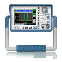
Rohde & Schwarz Smart Instruments UP300 Operating Manual (355 pages)
Audio Analyzer
Brand:
Rohde & Schwarz
| Category:
Measuring Instruments
| Size: 2 MB
Table of Contents
Table of Contents
5
Table of Contents
6
Data Sheet
11
Analyzer
11
Analog Audio Inputs
11
Digital Audio Inputs (Model R&S UP350 Only)
11
Measurement Functions
12
Filters
14
FFT Analyzer
15
Generator
15
Analog Audio Outputs
15
Digital Audio Outputs (Model R&S UP350 Only)
15
Signals
15
Sweep
17
Display of Results
17
Units
17
Graphical Display of Results
17
Audio Monitor
17
Digital Audio Protocol (Model R&S UP350 Only)
18
General Specifications
18
Safety Instructions
21
Certificate of Quality
31
EC Certificate of Conformity
32
1 Introduction
35
Application Range of the R&S UP300/350
35
Supplied Accessories
36
Warranty
36
2 Control Elements
37
Front View
37
Rear View: R&S UP300/350
38
Rear View: R&S UP350 (Digital Interface)
39
3 Putting the R&S UP300/350 into Operation
40
Unpacking the R&S UP300/350
40
Setting up the Instrument
40
Connecting the R&S UP300/350 to the AC Line
42
Switching on the R&S UP300/350
42
Function Test
43
Emc
43
Connecting a DUT
44
Connecting an External Keyboard
45
Connecting a USB Stick
46
4 Getting Started
47
Generator and Analyzer Settings
47
5 Manual Operating Concept
51
Overview of Operating Steps
52
Making Entries from the Keypad
53
Numeric Keys
54
Main Menu Selection Keys
54
Rotary Knob
55
Cursor Keys
55
Function Keys
55
Action Keys
56
BACK/SYS Key
56
Screen Display
57
Display Area
58
Menu Area
60
Function Area
60
Calling and Changing the Menus
61
Setting the Parameters
63
Direct Selection of Instrument Functions
63
Toggling a Setting
63
Selecting Settings
64
Entering Numerical Parameters
65
Entry with the Numeric Keys
65
Entry with the Cursor Keys and Rotary Knob
67
Overview of All Menus and Functions
69
Generator
69
FUNCTIONS Menu
69
SINE Menu
69
NOISE Menu
70
MULTISINE Menu
70
SINE BURST Menu
71
MOD DIST Menu
71
DFD Menu
71
POLARITY TEST Menu
72
DC OFFSET Menu
72
SWEEP RMS Menu
73
SWEEP RMS SELECTIVE Menu
74
SWEEP THD Menu
75
MONITOR Menu
76
CONFIG Menu
76
Analyzer
77
FUNCTIONS Menu
77
FREQUENCY, DC, RMS Menu
78
PEAK Menu
78
QUASI PEAK Menu
79
RMS SELECTIVE Menu
79
FFT Menu
80
THD Menu
80
DFD Menu
81
PHASE Menu
81
MOD DIST Menu
82
PROTOCOL Menu
82
SAMPLE RATE Menu
82
FILTER Menu
83
CONFIG Menu
83
Graph Menu
84
GRAPH MODE Menu
84
AXIS Menu
84
Y AXIS Menu
84
CURSORS Menu
85
System Menu (SYS Menu)
87
PRESET Menu
87
STATE Menu
87
FILE Menu
87
CONFIG Menu
88
SERVICE Menu
88
INFO Menu
88
CALIB Menu
88
6 Working with the R&S UP300/350
89
Factory Default Settings
89
Generator
90
Analyzer
94
Graph
97
System
97
Generator
98
Configuring Generator Parameters (CONFIG)
99
Selecting the Generator Type - Analog/Digital (R&S UP350 Only)
101
Analog Generator
102
Selecting the Generator Bandwidth
102
Selecting the Reference Potential of the Output Signal
103
Activating/Deactivating the Generator Output
104
Selecting the Type of the Level Range Switchover
105
Digital Generator (R&S UP350 Only)
107
Selecting the Sample Frequency of the Output Signal
107
Entering the Sample Frequency Offset
108
Setting the Validity Bit
108
Selecting the Valid Number of Bits in the Output Signal
109
Selecting the Interface Protocol
109
Setting the Generator Signal Type (FUNCTIONS)
110
Selecting Generator Functions
112
Configuring Signal Parameters
113
SINE (Sinewave Signal)
114
NOISE (Noise Signal)
119
MULTISINE (Multitone Signal)
122
SINE BURST (Sine Burst Signal)
132
MOD DIST (Two-Tone Signal in Accordance with IEC)
138
DFD (Difference Frequency Signal)
144
POLARITY TEST (Polarization Test Signal)
150
DC OFFSET (DC Voltage Component)
152
Sweep Rms
154
Sweep Rms Selective
171
Sweep Thd
190
Audio Monitoring Output (MONITOR)
209
Analyzer
212
Configuring the Analyzer (CONFIG)
213
Selecting the Analyzer Type - Analog/Digital (R&S UP350 Only)
215
Analog Analyzer
216
Selecting the Analyzer Bandwidth
216
Selecting the Reference Potential of the Input Signal
217
Selecting the Signal Source
218
Selecting the Signal Coupling
219
Selecting the Measurement Range Selection Mode
220
Selecting the Measurement Channel
221
Digital Analyzer (R&S UP350 Only)
222
Selecting the Sample Frequency of the Input Signal
222
Selecting the Input Signal
223
Selecting the Valid Number of Bits in the Input Signal
223
Setting the Measurement Functions (FUNCTIONS)
224
Selecting the Measurement Functions
226
Configuring the Measurement Parameters
227
Frequency, DC, Rms
228
PEAK (Peak Value)
237
QUASI PEAK (Quasi Peak Value)
243
RMS SELECTIVE (Selective RMS Value)
246
FFT (Frequency-Domain Display, Spectrum)
251
THD, THD+N, SINAD (Total Harmonic Distortion)
259
POLARITY (Polarity Test)
267
DFD (Difference Frequency Distortion)
268
PHASE (Measuring the Phase Difference between Channels)
272
MOD DIST (Modulation Distortion)
275
PROTOCOL (Protocol Analysis), (R&S UP350 Only)
278
SAMPLE RATE (Sample Frequency), (R&S UP350 Only)
281
Configuring the Filters (FILTER)
282
Selecting the Filters
283
Starting and Stopping the Measurements
285
Graph Menu
286
Selecting the Display Mode (GRAPH MODE)
287
Selecting the Display Parameters
288
Selecting the Display Mode
290
Scaling the X Axis (X AXIS)
292
Setting the Display Range
293
Selecting the Display Mode
295
Scaling the y Axis (y AXIS)
296
Setting the Display Range
297
Selecting the Display Mode
299
Trace Analysis Using Cursors (CURSORS)
300
Configuring the X Cursors
301
Activating/Deactivating the X Cursors
302
Assigning the X Cursors to a Trace (Ch 1 or Ch 2)
303
Positioning the X Cursors on a Maximum
303
Manual Positioning the X Cursors
305
Zooming the Display Area
307
Configuring the y Cursors
309
Activating/Deactivating the y Cursors
310
Manual Positioning the y Cursors
311
Zooming the Display Area
312
Full-Screen Display
314
System Menu (SYS Menu Key)
316
Instrument Default Setting (PRESET Menu)
317
Selecting and Calling the Instrument Default Setting
318
Start the Remote Control Manually
319
Displaying the Current Instrument Setting (STATE Menu)
320
User-Defined Settings (FILE Menu)
322
Saving and Loading a User-Defined Settings
323
Printing out a Screenshot
325
Saving the Measurement Results
327
System Settings (CONFIG Menu)
328
Setting the Date and Time
329
Selecting an Internal or External Reference Sources
331
Configuring the Instrument Interfaces
332
Setting the Screen Saver Mode
334
Selecting the Internal or External Monitors
336
Service Functions (SERVICE Menu)
337
Performing the Selftests
337
System Information (INFO Menu)
338
Displaying the Module Data
339
Displaying the Instrument Statistics
339
Displaying the System Messages
340
Adjustment Functions (CALIB Menu)
341
Starting the Auto Adjustment of the Generator Module
342
Starting the Auto Adjustment of the Analyzer Module
342
Starting the Auto Adjustment of the R&S UP300/350
343
7 Instrument Interfaces
344
Keyboard Connector (KEYB)
344
Monitor Connector (MON)
344
Reference Input and Output (10 Mhz In/Out)
345
USB Interface (PC, DEV)
345
Audio Monitoring Output (MON OUT)
345
8 Error Messages
346
System Messages
346
Warnings Indicating Impermissible Operating States
347
9 Index
349
Advertisement
Rohde & Schwarz Smart Instruments UP300 Programming Manual (23 pages)
Brand:
Rohde & Schwarz
| Category:
Laboratory Equipment
| Size: 0 MB
Table of Contents
Table of Contents
2
Introduction
3
Basic Details about Smart Instruments
3
Installing Instrument Drivers
4
Instrument Drivers
6
Integrating Drivers into a Project
6
Using "FS300 Basic Measurement" for the First Time
15
"Resource String" and "Virtual Instrument Name
17
Where to Find Help on the Driver Functions
19
Which Data Type to Use
19
References
21
Appendix: Contact Our Hotline
22
Keywords
23
Advertisement
Related Products
Rohde&Schwarz Smart Instruments UP350
Rohde & Schwarz Smart Instruments SM300
Rohde & Schwarz Smart Instruments 300 Series
Rohde&Schwarz Smart Instruments FS315
Rohde&Schwarz Smart Instruments AM300
Rohde & Schwarz Smart Instruments FS300
Rohde & Schwarz UPV
Rohde & Schwarz UPP
Rohde & Schwarz UPD
Rohde & Schwarz UPL
Rohde&Schwarz Categories
Measuring Instruments
Test Equipment
Portable Generator
Power Supply
Accessories
More Rohde&Schwarz Manuals
Login
Sign In
OR
Sign in with Facebook
Sign in with Google
Upload manual
Upload from disk
Upload from URL