Table of Contents
Advertisement
Available languages
Available languages
Quick Links
T E C H N O L O G Y F O R T H E W E L D E R ´ S W O R L D .
DE Betriebsanleitung / GB Operating instructions
FR Mode d'emploi / ES Instructivo de servicio
ZH 使用说明
S
®
DE Schweißbrenner-System ABIROB
A
®
EN Welding torch system ABIROB
A
®
FR Système de torche de soudage ABIROB
A
®
ES Antorcha de soldadura ABIROB
A
®
焊枪低
ABIROB
A
ZH
EN 60 974-7
GB/T 15579.7
www.binzel-abicor.com
Advertisement
Chapters
Table of Contents

Related Manuals for Abicor Binzel ABIROB


Summary of Contents for Abicor Binzel ABIROB
- Page 1 FR Mode d’emploi / ES Instructivo de servicio ZH 使用说明 ® DE Schweißbrenner-System ABIROB ® EN Welding torch system ABIROB ® FR Système de torche de soudage ABIROB ® ES Antorcha de soldadura ABIROB ® 焊枪低 ABIROB EN 60 974-7 GB/T 15579.7...
-
Page 2: Table Of Contents
DE-7 12.3 Verpackungen DE-18 Funktionsbeschreibung DE-8 Brennerhals DE-8 Anschlussmodul DE-8 Halter DE-8 Schlauchpaket DE-9 Inbetriebnahme DE-9 ® Brennerhals ABIROB ausrüsten DE-9 Schlauchpaket ausrüsten DE-10 Anschluss maschinenseitig montieren DE-11 Steuerleitung anschließen DE-11 Schutzgasmenge einstellen DE-11 Draht einführen DE-12 DE - 2... -
Page 3: Identifikation
Schweißpositionen einsetzbar. Diese Betriebsanleitung beschreibt nur das ® Schweißbrenner-System ABIROB A. Das Schweißbrenner-System darf nur mit Original ABICOR BINZEL Ersatzteilen betrieben werden. 1.1 EU-Konformitätserklärung im Sinne der EG-Niederspannungsrichtlinie 06/95/EG, Anhang III. Hiermit erklären wir, Alexander Binzel Schweisstechnik GmbH & Co. KG Kiesacker 7-9, 35418 Alten-Buseck dass das in der Betriebsanleitung beschriebene Schweißbrenner-System... -
Page 4: Produktbeschreibung
® 2 Produktbeschreibung ABIROB 2 Produktbeschreibung 2.1 Bestimmungsgemäße Verwendung ® Das flüssiggekühlte Schweißbrenner-System ABIROB A ist für den Roboter- und Automateneinsatz zu verwenden. Zur bestimmungsgemäßen Verwendung gehört auch das Beachten der vorgeschriebenen Betriebs-, Wartungs- und lnstandhaltungsbedingungen. 2.2 Nicht bestimmungsgemäße Verwendung Als nicht bestimmungsgemäß... -
Page 5: Abkürzungen
Isolationswiderstands-, Spannungsfestigkeits- und Schutzartklassifizierung Tool Center Point (Werkzeugmittelpunkt) Tab. 5 Abkürzungen 2.5 Typenschild ® Das Schweißbrenner-System ABIROB A ist mit einem Aufkleber am maschinenseitigen Anschlussgehäuse gekennzeichnet. Beachten Sie für alle Rückfragen folgende Angaben: • Angabe der Werksbescheinigung, Produktionsstempel auf dem ®... -
Page 6: Klassifizierung
• Brennerseitiger Knickschutz mit integriertem • Maschinenseitiger Knickschutz mit Zentralstecker Schaltergehäuse • Betriebsanleitung ® Mit dem ROBO Schlauchpaket ist das Schweißbrenner-System ABIROB A nicht funktionsfähig. Zur Erstbestückung benötigen Sie noch Bauteile, die von der jeweiligen Schweißaufgabe abhängig sind. Dies sind folgende: Tab. 6... -
Page 7: Transport
System benötigen Sie eine Einstellvorrichtung. Diese muss entsprechend der Konfiguration separat bestellt werden. Bestelldaten und Identnummern der Ausrüst- und Verschleißteile entnehmen Sie den aktuellen ABICOR BINZEL Ersatz- und Verschleißteilpreislisten. Kontakt für Beratung und Bestellung finden Sie im Internet unter www.binzel-abicor.com. 4.1 Transport Der Lieferumfang wird vor dem Versand sorgfältig geprüft und verpackt,... -
Page 8: Funktionsbeschreibung
Durch die einheitliche Schnittstelle am Anschlussmodul sind alle Brennerhälse untereinander kompatibel. 5.2 Anschlussmodul Das Anschlussmodul stellt die Verbindung zwischen Schweißbrenner und Schlauchpaket her. 5.3 Halter ® Mit dem Halter wird das Schweißbrenner-System ABIROB A über die Roboterhalterung CAT am Roboter befestigt. DE - 8... -
Page 9: Schlauchpaket
Reparaturarbeiten ist folgendes zu beachten: • Schalten Sie die Stromquelle aus. • Sperren Sie die Druckluftzufuhr ab. • Ziehen Sie den Netzstecker. HINWEIS ® • Die Inbetriebnahme des Schweißbrenner-Systems ABIROB A darf nur durch geschultes Personal erfolgen. ® 6.1 Brennerhals ABIROB A ausrüsten Gasdüse... -
Page 10: Schlauchpaket Ausrüsten
® 6 Inbetriebnahme ABIROB 5 Die Innensechskanntschrauben mit Hilfe des Innensechskanntschlüssels (7) festziehen. 6 Den Neck-Liner (5) anschlussseitig durch das Anschlussmodul (6) in den Brennerhals (4) einstecken. 6.2 Schlauchpaket ausrüsten Anschlussmodul Ausblasschlauch Schlauchpaket NOT-AUS-Kabel Zentralstecker Roboterhalterung CAT Steuerleitung Anschlussmutter Abb. 5 Schlauchpaket ausrüsten... -
Page 11: Anschluss Maschinenseitig Montieren
® ABIROB 6 Inbetriebnahme 6.3 Anschluss maschinenseitig montieren Siehe Abb. 5 Schlauchpaket ausrüsten auf Seite DE-10 Überprüfen Sie nochmals die korrekte Befestigung der Drahtführung. 1 Den Zentralstecker (5) und die -buchse am Drahtvorschubgerät zusammen fügen und mit der Anschlussmutter (6) sichern. -
Page 12: Draht Einführen
® 7 Betrieb ABIROB HINWEIS • Um eine Verstopfung durch Verunreinigung in der Schutzgasversorgung zu verhindern, müssen Sie das Flaschenventil vor dem Anschluss kurz öffnen. Dadurch werden evtl. Verunreinigungen ausgeblasen. • Alle Schutzgasverbindungen gasdicht herstellen. 1 Schutzgasflasche an Drahtvorschubsystem anschließen. -
Page 13: Schweißprozess
® ABIROB 8 Außerbetriebnahme WARNUNG Blendung der Augen Der durch das Schweißen erzeugte Lichtbogen kann Augen schädigen. • Schutzkleidung, bzw. Augenschutz tragen. HINWEIS • Die Bedienung ist ausschließlich Fachkräften vorbehalten. • Stellen Sie sicher, dass alle erforderlichen Parameter z.B. Schweißstrom, Drahtvorschub, usw. -
Page 14: Drahtführung Reinigen
• Tragen Sie während der Wartungs- und Reinigungsarbeiten immer Ihre persönliche Schutzkleidung. 1 Anhaftende Schweißspritzer entfernen. 2 Alle Verschraubungen auf festen Sitz prüfen. Im Reparaturfall bietet ABICOR BINZEL Werksreparaturen an. 9.1 Drahtführung reinigen 1 Schlauchpaket maschinenseitig lösen und in gestreckte Position bringen. 2 Überwurfmutter abschrauben und Führungsspirale bzw. Kunststoffseele herausziehen. -
Page 15: Brennerhals Reinigen
10Schlauchpaket (3) mit Überwurfmutter (4) an Zentralstecker (2) befestigen. 9.3 Brennerhals reinigen Um die Anlagenverfügbarkeit des Schweißroboters zu erhöhen, bietet ABICOR BINZEL die Möglichkeit der automatisierten Brennerreinigung. 1 Gasdüse abnehmen. 2 Schweißspritzer entfernen und mit ABICOR BINZEL- Antispritzerschutzmittel einsprühen. 3 Verschleißteile auf sichtbare Schäden überprüfen und ggf. austauschen. -
Page 16: Störungen Und Deren Behebung
® 10 Störungen und deren Behebung ABIROB 4 Ausrüstsatz bei Verschleiß oder Verschmutzung austauschen. 5 Trennstelle säubern und O-Ringe mit silikonfreiem Dichtfett einfetten. 6 TCP nach jedem Einsatz bzw. nach einer Kollision in der Einstellvorrichtung WH überprüfen. 10 Störungen und deren Behebung HINWEIS •... -
Page 17: Demontage
® ABIROB 11 Demontage Störung Ursache Behebung Porenbildung • Starke Spritzerbildung in der • Gasdüse reinigen Gasdüse • Unzureichende oder fehlende • Gasflascheninnhalt und Gasabdeckung Druckeinstellung überprüfen • Zugluft bläst Schutzgas weg • Schweißplatz mit Schutzwänden abschirmen Tab. 8 Störungen und deren Behebung 11 Demontage Die Demontage darf nur vom Fachhändler durchgeführt werden. -
Page 18: Werkstoffe
Betriebsmittelhersteller vorgegebenen Sicherheitsdatenblätter. Kontaminierte Reinigungswerkzeuge (Pinsel, Lappen usw.) müssen ebenfalls entsprechend den Angaben des Betriebsmittelherstellers entsorgt werden. 12.3 Verpackungen ABICOR BINZEL hat die Transportverpackung auf das Notwendigste reduziert. Bei der Auswahl der Verpackungsmaterialien wird auf eine mögliche Wiederverwertung geachtet. DE - 18... - Page 19 ® ABIROB 12 Entsorgung DE - 19...
- Page 20 Torch neck EN-8 Connection module EN-8 Mount EN-8 Hose assembly EN-9 Putting into operation EN-9 ® Equipping the ABIROB A torch neck EN-9 Equipping the hose assembly EN-10 Mounting the machine side connection EN-10 Connect the control line EN-11 Setting the shielding gas quantity EN-11...
-
Page 21: Identification
Protection Law and the Company Safety Ordinance must be heeded. In ® addition, the operator must ensure that the welding torch system ABIROB in connection with welding units comply with the EC EMC Directive (89/336/ EEC) and that the signal utilization of the integrated welding current monitoring against stray currents is installed properly. -
Page 22: Use Contrary To The Designated Use
® 2 Product Description ABIROB 2.2 Use contrary to the designated use Any use other than that described under "Designated Use" is considered contrary to the designated use. Unauthorized conversions or power increase modifications are not allowed. The warranty does not cover wearing parts and damage due to overloading or improper use. -
Page 23: Abbreviations
Tab. 5 Abbreviations 2.5 Type plate ® The welding torch system ABIROB A is identified by a sticker on the machine side connection housing. When making any inquiries, please remember the following information: • Specify the certificate of conformity, Production stamp on the torch neck,... -
Page 24: Safety Instructions
® 3 Safety Instructions ABIROB 3 Safety Instructions Observe the enclosed document Safety Instructions. 3.1 Classification The warning signs used in the operating instructions are divided into four different levels and are shown prior to specific work steps. Arranged in... -
Page 25: Transtransport
ABIROB 4 Components ® When equipped with the ROBO hose assembly, the welding torch system ABIROB A is not functioning. For the initial assembly, additional components are required which depend on the welding task at hand. They include the following: •... -
Page 26: Functional Description
The welding ® wire required for welding is fed by the welding torch system ABIROB A all the way to the contact tip. The contact tip transmits the welding current to the welding wire, producing an arc between the welding wire and work-piece. -
Page 27: Hose Assembly
• Switch off the power supply. • Cut off the compressed air supply. • Pull the mains plug. NOTE ® • The welding torch system ABIROB A may only be put into operation by trained personnel. ® 6.1 Equipping the ABIROB... -
Page 28: Equipping The Hose Assembly
® 6 Putting into operation ABIROB 5 Tighten the hexagonal head screws using the Allen key (7) . 6 Insert the Neck Liner (5) on the connection side through the connecting module (6) into the torch neck (4) . 6.2 Equipping the hose assembly... -
Page 29: Connect The Control Line
® ABIROB 6 Putting into operation Check once again whether the wire guide has been fastened correctly. 1 Join the central plug (5) and the central socket at the wire feed unit and secure them with a connection nut (6) . -
Page 30: Introducing The Wire
® 7 Operation ABIROB NOTE • Make all shielding gas connections gas-tight. 1 Connect shielding gas cylinder to the wire feeding system. 2 Set the gas quantity on the pressure reducer of the shielding gas cylinder. 6.6 Introducing the wire NOTE •... -
Page 31: Welding Process
® ABIROB 8 Putting out of operation WARNING Dazzling of the eyes The arc produced by welding may damage the eyes. • Wear protective clothing or eye protection. NOTE • The welding torch may only be operated by qualified personnel. -
Page 32: Cleaning The Wire Guide
1 Remove adhering welding spatter. 2 Check all screw joints for tight fit. ABICOR BINZEL offers repair services at the factory. 9.1 Cleaning the wire guide 1 Unscrew the hose assembly on the machine side and bring it into a stretched position. -
Page 33: Cleaning The Torch Neck
In order to increase the system availability of the welding robot, ABICOR BINZEL offers the option of automated torch cleaning. 1 Remove gas nozzle. 2 Remove welding spatter and spray gas nozzle with the ABICOR BINZEL anti-spatter agent. EN - 15... -
Page 34: Troubleshooting
® 10 Troubleshooting ABIROB 3 Check wearing parts for visible damage and replace them, if required. 4 Replace equipment kit when worn or soiled. 5 Clean separating point and O-rings with silicone-free sealing grease. 6 Check the TCP after each use or after a collision in the WH setup device. -
Page 35: Dismounting
® ABIROB 11 Dismounting Problem Cause Solution Pore formation • Strong spattering in the gas nozzle • Clean gas nozzle • Insufficient or missing gas cover • Check gas cylinder contents and pressure setting • Air currents blow shielding gas •... -
Page 36: Consumables
12.3 Packaging ABICOR BINZEL has reduced the shipping packaging to a minimum. Packaging materials are always selected with regard to their possible recycling ability. EN - 18... - Page 37 ® ABIROB 12 Disposal EN - 19...
- Page 38 ® Traduction des instructions de service dórigine ABIROB Traduction des instructions de service dórigine © Le constructeur se réserve le droit de modifier ce mode d´emploi à tout moment et sans avis préalable po ur des raisons d’erreurs d’impression, d’imprécisions éventuelles des informations contenues ou d’une amélioration de ce produit.
- Page 39 Nous, Alexander Binzel Schweisstechnik GmbH & Co. KG Kiesacker 7-9, D-35418 Alten-Buseck ® déclarons que le système de torche de soudage ABIROB A décrit dans le mode d’emploi en raison de sa conception et de son type de construction ainsi que dans la version dont nous disposons, est conforme aux exigences de sécurité...
-
Page 40: Description Du Produit
® 2 Description du produit ABIROB conforme comprend également l’observation des conditions de service, d’entretien et de maintenance prescrites. 2.2 Utilisation non conforme à l'emploi prévu Toute autre utilisation que celle décrite dans la section "Utilisation conforme à l'emploi prévu" est considérée comme non conforme. Des transformations ou modifications servant à... -
Page 41: Abréviations
Pour tous renseignements complémentaires, les informations suivantes sont nécessaires : • Indication de l’attestation d’usine, Données de production sur le col de cygne, par ex. : ABIROB A360 22, Indications sur l'autocollant FR - 5... -
Page 42: Consignes De Sécurité
® 3 Consignes de sécurité ABIROB 3 Consignes de sécurité Observer les instructions de sécurité du document joint. 3.1 Classification Les consignes d'avertissement utilisées dans ce mode d'emploi sont divisées en quatre niveaux différents et les travaux spécifiques sont marqués par ces consignes placées en tête. -
Page 43: Transport
Tab. 6 Matériel fourni ® Les faisceaux pour le système de torche de soudage ABIROB A sont disponibles en longueurs standard de 1 à 3,5 m et en plusieurs longueurs spécifiques au client. Pour un système complet, vous avez besoin d'un marbre de contrôle/rectification. -
Page 44: Description Du Fonctionnement
(MIG) et le gaz actif (MAG). 5.1 Col de cygne ® Pour les cols de cygne standard des types ABIROB A 360, A500 les versions suivantes sont disponibles : droites et inclinées de 22°, 35° et 45°. Des versions spéciales sont fabriquées sur demande en fonction de l'application. -
Page 45: Faisceau
• l'alimentation en air comprimé soit coupée. • la fiche secteur soit débranchée. REMARQUE ® • La mise en service du système de torche de soudage ABIROB A ne doit être effectuée que par un personnel qualifié. ® 6.1 Equiper les cols de cygne ABIROB... -
Page 46: Equiper Le Faisceau
® 6 Mise en service ABIROB 4 Insérer le col de cygne (4) jusqu'à la butée dans le module de raccordement (6). 5 Serrer les vis à six pans creux à l'aide de la clé mâle coudée pour vis à six pans creux (7). -
Page 47: Monter Le Raccord Côté Poste
® ABIROB 6 Mise en service 6.3 Monter le raccord côté poste Voir Fig. 5 Equiper le faisceau page FR-10 Contrôlez encore une fois la fixation correcte de la gaine guide-fil. 1 Joindre le connecteur central (5) et le raccord européen sur le dévidoir et les serrer à... -
Page 48: Insérer Le Fil
® 7 Fonctionnement ABIROB REMARQUE • Afin d'éviter une obstruction dans l'alimentation de gaz protecteur par des impuretés, vous devez brièvement ouvrir la valve de la bouteille de gaz avant le raccordement. Ainsi, les impuretés éventuelles sont éliminées. • Veiller à ce que tous les raccordements au gaz protecteur soient étanches au gaz... -
Page 49: Processus De Soudage
® ABIROB 8 Mise hors service DANGER Risque de brûlures Lors des travaux de soudage, il existe un risque de formation de flammes dû à des étincelles jaillissantes ou des scories chaudes. • Enlever tous les matériaux inflammables de la zone de travail. -
Page 50: Nettoyer Le Guide-Fil
1 Enlever les projections de métal adhérentes. 2 Vérifier le serrage des raccords à vis. Les réparations peuvent être effectuées par ABICOR BINZEL. 9.1 Nettoyer le guide-fil 1 Desserrer le faisceau côté poste et le tendre. -
Page 51: Raccourcir La Gaine Guide Fil Acier
® ABIROB 9 Entretien et nettoyage 4 Glisser la gaine guide-fil acier ou la gaine guide-fil synthétique adaptée dans le câble transport de fil et serrer l'écrou arrêt de gaine. 9.2 Raccourcir la gaine guide fil acier REMARQUE • Les gaines guide-fil aciers ou les gaines guide-fil synthétiques neuves et non-utilisées doivent être raccourcies d'après la longueur réelle du... -
Page 52: Nettoyer Le Col De Cygne
10Fixer le faisceau (3) au connecteur central (2) à l'aide de l'écrou-raccord (4). 9.3 Nettoyer le col de cygne Pour augmenter la disponibilité du robot de soudage, ABICOR BINZEL offre la possibilité d'un nettoyage automatique de la torche. 1 Enlever la buse gaz. - Page 53 ® ABIROB 11 Démontage Défaut Origine Solution Le fil est coincé • Réglage de paramètres incorrects • Contrôler le réglage et le corriger, si nécessaire dans le tube- contact • Tube-contact usé • Remplacer Avance de fil • Gaine guide fil acier ou synthétique •...
-
Page 54: Démontage
Les outils de nettoyage contaminés (pinceau, chiffon etc.) doivent être également éliminés selon les indications du fabricant des produits consommables. 12.3 Emballages ABICOR BINZEL a réduit l'emballage de transport au nécessaire. Lors du choix des matériaux d'emballage, veiller à ce que ces derniers soient recyclables. FR - 18... - Page 55 ® ABIROB 12 Elimination FR - 19...
- Page 56 ® Traducción del manual de instrucciones original ABIROB Traducción del manual de instrucciones original © El fabricante se reserva el derecho a cambiar este instructivo de servicio sin previo aviso en cualquier momento que esto pudiera ser necesario como resultado de errores de imprenta, incorrecciones en la información recibida o mejoras en el producto.
-
Page 57: Identificación
A se utiliza en la industria con gases inertes (MIG) o activos (MAG). Esta versión es refrigerada por aire y puede utilizarse en todas las posiciones de soldadura. Este manual de instrucciones ® describe sólo la antorcha de soldadura ABIROB A. La antorcha de ® soldadura ABIROB A debe utilizarse solamente con piezas de recambio originales de ABICOR BINZEL. -
Page 58: Utilización No Conforme A Lo Prescrito
® 2 Descripción del producto ABIROB establecidas para servicio, mantenimiento y reparación es parte de la utilización conforme a lo prescrito. 2.2 Utilización no conforme a lo prescrito Cualquier otra utilización no descrita en "Utilización conforme a lo prescrito" se considera como no conforme a lo prescrito. Las modificaciones del incremento de capacidad, realizadas por decisión propia, no están... -
Page 59: Abreviaciones
Para todas las preguntas, tener en cuenta los datos siguientes: • Indicación del certificado de conformidad, Sello de producción en el ® cuello de antorcha, p. ej. ABIROB A 360 22, Indicaciones en el adhesivo ES - 5... -
Page 60: Instrucciones De Seguridad
• Protección contra doblado en el lado de la máquina con adaptador central ® La antorcha de soldadura ABIROB A no está lista para el funcionamiento con el conjunto de cables ROBO. Para el equipamiento inicial se necesitan componentes que dependen de la tarea de soldadura correspondiente. -
Page 61: Trtransporte
ABIROB 4 Lieferumfang ® Los conjuntos de cables de la antorcha de soldadura ABIROB A pueden suministrarse en longitud estándar de 1 a 3,5 m o a medida específica del cliente. Para un sistema completo se necesita un verificador de cuello. Eso debe pedirse por separado según la configuración. -
Page 62: Descripción Del Funcionamiento
Todos los elementos juntos forman una unidad funcional que, provista de los materiales adecuados, genera un arco para soldar. El hilo para soldar se ® transporta a través de la antorcha de soldadura ABIROB A al tubo de contacto. El tubo de contacto transmite la corriente de soldadura al hilo de soldadura y genera un arco entre el hilo y la pieza. -
Page 63: Conjunto De Cables
• Cerrar el suministro de aire comprimido. • Desconectar el conector de red. INDICACIÓN ® • La puesta en servicio de la antorcha de soldadura ABIROB A sólo debe realizarse por personal instruido. ® 6.1 Equipar el cuello de antorcha ABIROB... -
Page 64: Equipar El Conjunto De Cables
® 6 Puesta en servicio ABIROB 4 Insertar el cuello de antorcha (4) hasta el tope en el módulo de conexión (6). 5 Utilizar la llave Allen (7) para apretar los tornillos Allen. 6 Insertar la sirga para el cuello (5) por la parte trasera del módulo de conexión (6) hacia el cuello de la antorcha (4). -
Page 65: Montar La Conexión En El Lado De La Máquina
® ABIROB 6 Puesta en servicio 6.3 Montar la conexión en el lado de la máquina Véase Fig. 5 Equipar el conjunto de cables en página ES-10 Controlar otra vez si el guía hilos está sujetado correctamente. 1 Conectar el adaptador (5) y la hembrilla central en la devanadora y sujetar mediante una tuerca de conexión (6). -
Page 66: Introducir El Hilo
® 7 Operación ABIROB INDICACIÓN • Antes de conectar, abrir brevemente la válvula de la botella para evitar obturar la instalación de suministro de gas inerte por suciedad. De este modo se expulsan eventuales suciedades. • Establecer todas las conexiones para gas inerte de modo hermético. -
Page 67: Proceso De Soldadura
® ABIROB 8 Desconexión de la antorcha ¡PELIGRO! Riesgo de quemaduras Durante los trabajos de soldadura pueden producirse chispas, por piezas ardientes o por escoria caliente. • Controlar si hay focos del incendio en la zona de trabajo. • Poner a disposición medios apropiados de protección contra incendios en el puesto de trabajo. -
Page 68: Limpiar El Guía Hilos
1 Eliminar proyecciones de soldadura adherentes. 2 Controlar si las uniones atornilladas están bien sujetas. En caso de reparaciones ABICOR BINZEL ofrece reparaciones en fábrica. 9.1 Limpiar el guía hilos 1 Soltar el conjunto de cables en el lado de la máquina y colocarlo en posición estirada. -
Page 69: Recortar La Sirga
® ABIROB 9 Mantenimiento y limpieza 3 Limpiar el conductor de hilo desde ambos lados con aire comprimido. 4 Insertar la sirga en el conjunto de cables a través del conductor de hilo y sujetarla mediante la tuerca de unión. -
Page 70: Limpiar El Cuello De Antorcha
(4). 9.3 Limpiar el cuello de antorcha Para aumentar la vida de consumibles del robot de soldadura, ABICOR BINZEL ofrece la posibilidad de limpiar automáticamente la antorcha. 1 Sacar la tobera de gas. 2 Eliminar las salpicaduras de soldadura y rociar la tobera con el líquido de protección contra salpicaduras de ABICOR BINZEL. -
Page 71: Desmontaje
® ABIROB 11 Desmontaje Avería Causa Eliminación El hilo se ha • Parámetros ajustados no son • Controlar y corregir los ajustes correctos pegado en la tobera de contacto • Tubo de contacto desgastado • Reemplazar Problemas de • Sirga obstruida •... -
Page 72: Materiales
Los útiles de limpieza (cepillos, paños, etc.) también deben eliminarse según las indicaciones del fabricante de los combustibles. 12.3 Embalajes ABICOR BINZEL ha reducido el embalaje de transporte a un mínimo necesario. Al seleccionar los materiales de embalaje, se tiene en cuenta un posible reciclaje. - Page 73 ® ABIROB 12 Eliminación ES - 19...
- Page 74 ® 使用说明 ABIROB 使用说明 © 如果由于产品的改进,印刷错误或不准确,制造商有权在任何时 候、且不作预先通 知的情况下修正或更改此 《操作说明书》 。然 而,这些修改将会作为 《说明书》的后 续版本的组成部分 识别鉴定 操作 ZH-3 ZH-11 欧盟符合性说明 焊接过程 ZH-3 ZH-11 使用方的责任 ZH-3 终止工作状态 ZH-11 产品介绍 ZH-3 合理使用 维护和清洗 ZH-3 ZH-12 非合理使用 布线清洗 ZH-3 ZH-12 技术数据 剪短导环 ZH-4 ZH-13 缩写...
-
Page 75: 识别鉴定
1 识别鉴定 ® ABIROB A 焊枪用于工业和手工业领域内的惰性保护气体焊接(MIG), 或者活性气体焊接 (MAG) 。 焊枪使用气体冷却并能够全方位作业。 ® ® 本使用说明是关于 ABIROB A. ABIROB A 焊枪只允许使用 ABICOR BINZEL 原配件操作。 1.1 欧盟符合性说明 根据欧共体低压规章 EC 低电压指令 06/95/EC, 附件 III. 我们特此声明,Alexander BINZEL Schweisstechnik GmbH & Co. KG 宾 采尔焊接技术有限公司 , Kiesacker 7-9, 35418 Alten-Buseck ®... -
Page 76: 技术数据
® 2 产品介绍 ABIROB 2.3 技术数据 焊接环境温度 - 10 C 至 + 40 C 运输和存贮 - 25 C 至 + 55 C 空气相对湿度 不超过 90 % ,在 20 C 时 表格 2 温度 电压类别 电极极性 通常为阳极 焊丝类型 普通圆型焊丝 使用方式 手握式... -
Page 77: 安全须知
电压测定 绝缘电阻,耐压强度 和保护级划分 工具零点 表格 5 缩写 2.5 铭牌 ® ABIROB A 系统通过连接盒上的标签进行标识 . 垂询时请提供以下信息 : • 出厂证明 , 焊枪颈上边的生产印章,如 ABIROB A360 22, 标签 3 安全须知 请务必查阅及遵照附件中的安全指导 . 3.1 分类 说明书中的警告分为个不同层次,并分别于具体工作之前出现。 按 重要性递减顺序表示 : 危险 指直接面临的危险。 如果不被排除,将引起严重伤亡。 ZH - 5... -
Page 78: 紧急情况
其它措施参见使用说明 " 电源 " 以及附带装置的说明书 . 4 供货范围 • 焊枪的铰接弯曲保护和内装的开关盒 • 原配的铰接弯曲保护带主插销 • 使用说明 ® 使用 ROBO- 套管 ABIROB A 无法工作 . 您还需要配置的其他部件 , 依具体的焊接工作而定 . 部件如下 : • 枪颈 ( 适当大小和尺寸 ) • 支架 ( 用于和机器人固定 ) • 磨损件 ( 专门订货 ) 表格... -
Page 79: 功能介绍
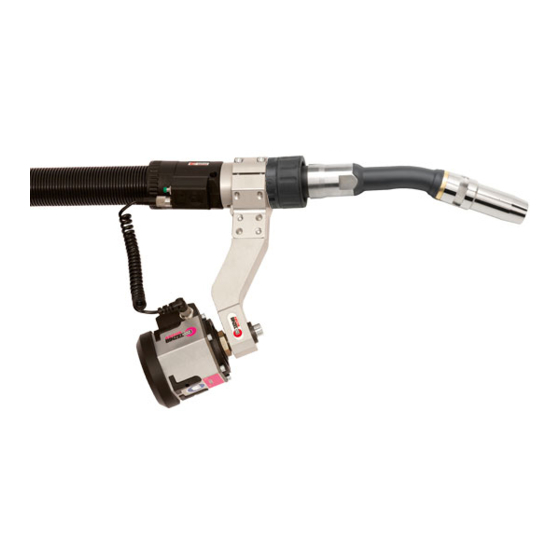
返回包装 尽可能使用原包装及原包装材料 . 如果您有关于包装和运输保险的问题 , 请与您的供货商联系 . 表格 7 运输 4.2 存储 封闭室内存储的物理条件 : 表格 2 温度 ZH - 4 5 功能介绍 ® 高效的 ABIROB A 系统包括以下部件 : 枪颈 套管 支架 连接块 主插销 ® 插图 3 ABIROB A 焊枪系统... -
Page 80: Abirob ® A 焊枪颈的装配
6 启用 ABIROB 5.4 套管 气冷却的套管向焊枪提供焊接用的全部所需,如焊接电源,保护气 体和空气。 6 启用 危险 无意启动的伤害危险 在维护,保养,拆散和修理的整个过程中须注意 : • 切断电源。 • 切断压缩气体供应。 • 拔掉电源插销。 提示 ® • ABIROB A 焊枪系统的启用须由受过专门培训的人员完成。 ® 6.1 ABIROB A 焊枪颈的装配 喷嘴 焊枪颈 内六角扳手 导电嘴 颈套 通用扳手 喷嘴座 连接块 ® 插图 4 ABIROB A 焊枪颈的装配... -
Page 81: 装配套管
® 6 启用 ABIROB 6.2 装配套管 连接块 吹气管 套管 紧急关闭电缆 主插销 机器人支撑 CAT 控制电缆 火花塞接头 插图 5 装配套管 提示 • 按照您的使用要求选择合适的焊丝和相应的送丝结构。 • 断丝和正确的组装请见以下章节 : 见 9 维护和清洗 ZH - 12 • 导环 = 钢及不锈钢 • 塑料芯 = 铝,铜,镍和不锈钢 1 将套管 (7) 展开放平,沿焊枪颈与连接块 (1) 固定。... -
Page 82: 接通控制线
® 6 启用 ABIROB 6.4 接通控制线。 原配控制线不带插头。 客户可根据个人要求配置插头。 如果您提供 详尽的要求和信息,可以提供完全配置的控制线。否则根据电源选 择合适的插头,按照图纸接通相应的线芯。 R 1,2k a = 绿 , b = 白 , c = 棕 , d = 黄 ( 带绝缘层 ), e = 灰 ( 带绝缘层 ), f = 蓝 ( 带绝缘层 ), g = 粉... -
Page 83: 焊接过程
® 7 操作 ABIROB 7 操作 危险 吸入磷气导致窒息和中毒 焊接使用含氯溶剂去脂的工件时会产生磷气。 • 不吸入焊烟和蒸气。 • 注意有足够的新鲜空气。 • 焊接前用清水冲洗工件。 • 焊接作业附近不要放置含氯的去油池。 危险 烧伤危险 焊接时产生的焊花,烧热的工件和滚烫的熔渣可能引发火苗。 • 检查作业周围是否有着火危险。 • 焊接作业位置须备有适当的防火,灭火设备。 • 焊接后注意让工件冷却。 • 焊接前将耐火嵌固定于工件或作业台。 警告 刺眼 焊接时电弧可能伤害眼睛。 • 穿戴防护衣和眼罩。 提示 • 操作须由专业人员完成。 • 确认已按照焊接要求对所有参数进行设定,如焊接电流,送丝 等。 7.1 焊接过程... -
Page 84: 维护和清洗
• 拔掉电源插销。 危险 电震 电缆故障造成危险电压。 • 检查所有带电线缆和连接是否正确安装。 • 更新受损,变形和耗损部件。 提示 • 建议的维护间隔为参考,是根据一个班作业的。 • 维护和清洗工作必须由受过培训和专业人员完成。 • 进行维护和清洗工作时须穿戴个人防护衣。 1 去除滞留的焊花。 2 检查是否所有螺栓夹套牢固。 ABICOR BINZEL 提供厂家修理。 9.1 布线清洗 1 摘下套管并展开。 2 取下中继螺母和导环及塑料芯。 警告 损伤危险 摆动部分可能引发严重危险。 • 吹气打扫布线时须穿戴防护衣,尤其眼罩。 3 用压缩气吹净送丝管两侧。 安装好的 导丝管 缆管 连接螺母固定... -
Page 85: 剪短导环
(5) 和 (6) 推进 (2) 。 定位螺母 的 中央插头 9 将 螺纹一边推进 (2) 并上紧。 将电缆组件 连接螺母 中央插头 (2) 用 (4) 与 (2) 上紧。 9.3 焊枪颈的清洗 为了更好地利用机器人设备 , ABICOR BINZEL 提供焊枪自动清洗。 1 取下喷嘴。 2 将焊花去除并使用 ABICOR BINZEL- 喷射防护剂喷洒。 ZH - 13... -
Page 86: 干扰和排除
® 10 干扰和排除 ABIROB 3 检查磨损件是否已耗损,必要时更换。 4 磨损或脏污时更换配套装置。 5 洗净接合点,并用不含硅密封脂将 O 密封圈上油。 6 每次使用或在 WH 调节装置内撞击后,须检查 TCP。 10 干扰和排除 提示 • 如果以下措施仍无法排除干扰,请与销售方或制造方联系。 • 同时注意有关焊接技术细节的使用手册,如电源,压缩气管。 干扰 原因 排除 枪颈变热 • 导电嘴松弛 • 检查并上紧 • 导电嘴焊枪一方和靠近工件处不紧 • 检查并上紧 按键失灵 • 控制电缆不通 / 故障... -
Page 87: 废物处理
见 11 拆散 ZH - 14 12.1 原料 本产品主要原料为塑料,钢和有色金属。 钢料和有色金属可以回炉, 并重新使用。对采用的塑料进行了标识,以便于将来回炉处理时的 材料分类。 12.2 辅助材料 润滑油脂和清洗剂不可进入地下或者排水系统。 这些物质须使用适 当的容器保存,运输和处理。 注意遵守当地的有关规定和辅助材料 生产商提供的有关处理的指示。 相关联的清洗工具 ( 毛刷 , 抹布等 ) 也必须按照生产商的指示进行处理 . 12.3 包装 ABICOR BINZEL 尽量减少运输包装 . 包装材料尽量采用可回收再生材 料 . ZH - 15... - Page 88 T E C H N O L O G Y F O R T H E W E L D E R ´ S W O R L D . Alexander Binzel Schweisstechnik GmbH & Co. KG Postfach 10 01 53 • D–35331 Giessen Tel.: ++49 (0) 64 08 / 59–0 Fax:...
Need help?
Do you have a question about the ABIROB and is the answer not in the manual?
Questions and answers