Table of Contents
Advertisement
Quick Links
Advertisement
Table of Contents

Related Manuals for Abicor Binzel ALPHA Series


Summary of Contents for Abicor Binzel ALPHA Series
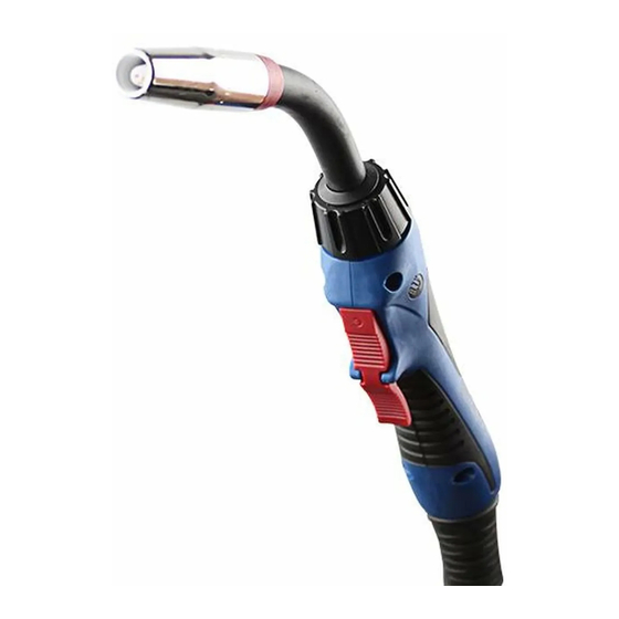
- Page 1 ABICOR ALPHA SERIES Instruction Manual www.binzel-abicor.com...
-
Page 3: Table Of Contents
CONTENTS Page Neckliner lengths and installation ..............4, 5 Installing gun (cable) liners ................ 5-7 Installing connector kit for direct mount models: internal gas ......8 Installing connector kit for direct mount models: external gas ......9 Consumable chart ALPHA 1 ...............10 Consumable charts ALPHA 2 ..............11, 12 Consumable charts ALPHA 3 ..............13, 14 Consumable charts ALPHA 4 ..............15, 16 Trouble-shooting: Porosity ................17... -
Page 4: Neckliner Lengths And Installation
Installation of neckliners in slip-on and threaded nozzle swannecks If replacing an existing neckliner: Unscrew the swanneck, remove the old neckliner and measure its length. Carefully cut the new neckliner to the same length as the old liner with a pair of sharp cutters. -
Page 5: Installing Gun (Cable) Liners
NECKLINERS: CUT MEASUREMENTS Please note: Swanneck machining tolerances result in small variances in length; consequently the measurements given below are intended for reference only (for example, to help identify loose cut neckliners). ALPHA SWANNECKS ALPHA SWANNECKS ALPHA 1: 180 Amp ALPHA 3: 350 Amp A1-22 5-29/32”... - Page 6 Installation of plastic liners for aluminum/ stainless steel in direct mount guns Lay the torch out straight and remove the liner retaining nut at the wire feed end of the torch cable. Remove the existing gun liner if fitted. If switching from a steel liner, remove the swanneck and fit the appropriate brass neckliner for aluminum –...
- Page 7 Installation of Teflon liners for aluminum/ ® stainless steel in Euro quick-connect guns Lay the torch out straight and remove the liner retaining nut at the wire feed end of the torch cable. Remove the existing gun liner if fitted. If switching from a steel liner, remove the swanneck and fit the appropriate brass neckliner for aluminum –...
-
Page 8: Installing Connector Kit For Direct Mount Models: Internal Gas
Assembly instructions for direct plug connector kits: internal gas Trigger lead jumper Direct Plug Torch Rear End Connector Kit Internal Gas Connector plug Allen key Set screw Thread the connector plug into the rear of the torch (the connector plug may differ from the one shown). -
Page 9: Installing Connector Kit For Direct Mount Models: External Gas
Assembly instructions for direct plug connector kits: external gas (Lincoln std. shown) Gas hose Direct Plug Torch Rear End Allen key Connector Kit nipple Gas seal Lincoln Insulating Standard Connector plug sleeve Set screw Trigger lead jumper Slide the insulating sleeve over the connector plug (wide end facing the torch) and screw the plug into the torch rear end. -
Page 17: Trouble-Shooting: Porosity
TROUBLESHOOTING: POROSITY (SUMMARY) Causes of Porosity Possible Solutions BASE METAL CONTAMINATION Impurities on base metal. a. Remove contamination; clean surfaces b. Use of specific wire/gas mix for specific types of impurities. FILLER METAL CONTAMINATION Impurities on filler metal (wire). a. Replace wire. b. -
Page 18: Troubleshooting: General Guide
The efficient feeding of the welding wire is depen- dent on the liners fitting correctly. Consult the liner installation instruc- tions on pages 2-4 or contact your local authorized ABICOR Binzel distributor for additional help. Spatter on wire. - Page 19 TROUBLESHOOTING: GENERAL GUIDE Problems/Causes Possible Solutions SPATTER Too fast or too slow wire Set the wire feed rate and voltage in accordance with good welding feed for the arc voltage. practices as recommended by a qualified welding engineer. Too long an arc. Adjust the wire feed and voltage so that the arc is in accordance with good welding practice for the joint to be welded.
-
Page 20: Swanneck Dimensions: Alpha 1
Note complete weld parameters, including welding current (Amps), exceeded. welding voltage, wire feed speed, type and size of wire, type of gas and fIow rate of gas and consult your local Authorized ABICOR Binzel a distributor. Dirty connection Remove swanneck and inspect interface for dirt build-up. Periodic cleaning is necessary. -
Page 21: Swanneck Dimensions: Alpha 2
SWANNECK DIMENSIONS: ALPHA 2 THREADED A2T-22 A2T-60 A2T-45 SWANNECK DIMENSIONS: ALPHA 3 THREADED A3T-22 A3T-60 A3T-45 Approximate x and y measurements are in millimeters and are taken from the end of the contact tip with spray arc set-up. -
Page 22: Swanneck Dimensions: Alpha 4
SWANNECK DIMENSIONS: ALPHA 4 THREADED A4T-22 A4T-60 A4T-45 Approximate x and y measurements are in millimeters and are taken from the end of the contact tip with spray arc set-up. - Page 24 Alexander Binzel Corporation 650 Medimmune Ct., Suite 110, Frederick, MD 21703-8619 Tel: 301.846.4196 Fax: 301.846.4497 www.binzel-abicor.com Alexander Binzel Corporation Binzel S.A. de C.V. Alexander Binzel Canada, Inc. 650 Medimmune Ct., Suite 110 Municipio de Pabellon de Arteaga 102 5200 Dixie Rd, Unit 13 Frederick, MD 21703-8619 Valle de Aguascalientes 20358 Mississauga, ON L4W 1E4...
Need help?
Do you have a question about the ALPHA Series and is the answer not in the manual?
Questions and answers