Advertisement
Quick Links
Advertisement

Related Manuals for Ripley ODM RP 460


Summary of Contents for Ripley ODM RP 460
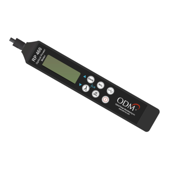
- Page 1 RP 460 How to Set a Reference and Perform an Insertion Loss Test...
-
Page 2: Table Of Contents
Introduction Performing a test for Insertion Loss (also commonly called dB Loss or Attenuation) on a fiber optic cable requires an Optical Power Meter (OPM) and an Optical Light Source (OLS). This document outlines the specific steps which must be taken with ODM’s RP 460 optical power meter to perform insertion loss testing on a variety of fiber types and setups. -
Page 3: Example 1: Singlemode Fiber, Point-To-Point, 1 Jumper
Example 1: Singlemode Fiber, Point-to-Point, 1 Jumper Fiber Type Singlemode Connectors Used Test Jumper Setup Single OPM Used RP 460 OLS Used DLS 355 Fiber-Under-Test The fiber-under-test is singlemode with LC 400m Fiber connectors on each end. The fiber-under-test may be up to 250 kilometers long. - Page 4 Referencing Setup The connectors on the Test Jumper should be cleaned to appropriate standards. Use an inspection scope to verify fiber cleanliness. Plug the connectors on the Test Jumper into the RP 460 and DLS 355. The RP 460 should be in the dBm measurement mode. If it is not in the dBm mode, press the dB/dBm button once to put it into the dBm mode.
-
Page 5: Example 2: Singlemode Fiber, Point-To-Point, 2 Jumpers
Example 2: Singlemode Fiber, Point-to-Point, 2 Jumpers Fiber Type Singlemode Connectors Used Test Jumper Setup Double OPM Used RP 460 OLS Used DLS 355 Fiber-Under-Test The fiber-under-test is singlemode with LC connectors on each end. This method allows testing Connectors Inside Bulkheads of connectors inside bulkheads. - Page 6 Referencing Setup The connectors on the Test Jumper should be cleaned to appropriate standards. Use an inspection scope to verify fiber cleanliness. Plug the connectors on the Test Jumper into the RP 460 and DLS 355. The RP 460 should be in the dBm measurement mode. If it is not in the dBm mode, press the dB/dBm button once to put it into the dBm mode.
-
Page 7: Example 3: Singlemode Fiber, Paired, Loopback Jumper
Example 3: Singlemode Fiber, Paired, Loopback Jumper Fiber Type Singlemode Connectors Used Test Jumper Setup Loopback OPM Used RP 460 OLS Used DLS 355 Fiber-Under-Test The fiber-under-test is paired singlemode with paired LC connectors on each end. The 400m Paired Fiber fiber-under-test may be up to 250 kilometers long. - Page 8 Referencing Setup The connectors on the Test Jumper and loopback should be cleaned to appropriate standards. Use an inspection scope to verify fiber cleanliness. Plug the connectors on the Test Jumper into the RP 460 and DLS 355. Plug the loopback adapter on to the paired LC side of the Test Jumper. The RP 460 should be in the dBm measurement mode.
-
Page 9: Example 4: Multimode Fiber, Point-To-Point, 1 Jumper
Example 4: Multimode Fiber, Point-to-Point, 1 Jumper Fiber Type Multimode Connectors Used Test Jumper Setup Single OPM Used RP 460 OLS Used DLS 350 Fiber-Under-Test The fiber-under-test is multimode with LC 400m Fiber connectors on each end. In this example, the fiber-under-test is 400 meters long. - Page 10 Referencing Setup The connectors on the Test Jumper should be cleaned to appropriate standards. Use an inspection scope to verify fiber cleanliness. Plug the connectors on the Test Jumper into the RP 460 and DLS 350. The RP 460 should be in the dBm measurement mode. If it is not in the dBm mode, press the dB/dBm button once to put it into the dBm mode.
-
Page 11: Example 5: Multimode Fiber, Paired, Loopback Jumper
Example 5: Multimode Fiber, Paired, Loopback Jumper Fiber Type Multimode Connectors Used Test Jumper Setup Loopback OPM Used RP 460 OLS Used DLS 350 Fiber-Under-Test The fiber-under-test is paired multimode with paired LC connectors on each end. The 400m Paired Fiber fiber-under-test may be up to 250 kilometers long. - Page 12 Referencing Setup The connectors on the Test Jumper and loopback should be cleaned to appropriate standards. Use an inspection scope to verify fiber cleanliness. Plug the connectors on the Test Jumper into the RP 460 and DLS 350. Plug the loopback adapter on to the paired LC side of the Test Jumper. The RP 460 should be in the dBm measurement mode.
Need help?
Do you have a question about the ODM RP 460 and is the answer not in the manual?
Questions and answers