Advertisement
Quick Links
RZ/N1S Group
CONNECT IT! ETHERNET RZ/N1S-DB
Introduction
RZ/N1 is a family of scalable ARM® based industrial Ethernet switches. Due to the integrated performant
ARM® Cortex®-A7 CPU, they are ideal choice for building products such as Programmable Logic Controllers
(PLC), complex remote-IO slaves, industrial switches, gateways or operator terminals.
RZ/N1 Family consists of three devices, out of which the RZ/N1S, is an industrial ethernet communication
System on Chip with a 3 or 5-ports, depending on the respective chosen package 324BGA/196BGA.
This guide shall assist you to quickly start with your evaluation of the RZ/N1S device on the related Solution
Kit board(s) and the Solution Kit software and documentation. It represents a short guide for the first time users
with the instructions for the first startup of the board.
In addition to this document, please be aware of the extensive documentation on RZ/N1 devices, evaluation
boards and software that you may find in the Solution Kit Documentation directory.
The Solution Kit boards can solely be used for evaluation purposes. It is not allowed to use the boards for
commercial purposes.
List of reference documents
Document name
User's Manual: System Introduction, Multiplexing, Electrical and Mechanical Information
User's Manual: System Control and Peripheral
User's Manual: Peripherals
User's Manual: R-IN Engine and Ethernet Peripherals
User's Manual: Generic Open Abstraction Layer
RZ/N1S Development Board Schematic
RZ/N1S Development Board Setup Notes
RZ/N1 U-Boot User Manual
R01QS0021ED0060 Rev. 0.60
Jan.31.2020
Quick Start Guide
Page 1 of 24
Advertisement

Subscribe to Our Youtube Channel
Related Manuals for Renesas RZ/N1S


Summary of Contents for Renesas RZ/N1S
- Page 1 System on Chip with a 3 or 5-ports, depending on the respective chosen package 324BGA/196BGA. This guide shall assist you to quickly start with your evaluation of the RZ/N1S device on the related Solution Kit board(s) and the Solution Kit software and documentation. It represents a short guide for the first time users with the instructions for the first startup of the board.
-
Page 2: List Of Abbreviations And Acronyms
RZ/N1S Group CONNECT IT! ETHERNET RZ/N1S-DB List of Abbreviations and Acronyms Abbreviation Full Form Application Programming Interface Board Support Package CANopen Bus Protocol Device Level Ring Protocol EtherCAT / ECAT EtherCAT Network Protocol EtherNet/IP / EIP EtherNet/IP Network Protocol Ethernet POWERLINK Network Protocol... - Page 3 – a communication block based on the proven multi-protocol R-IN Engine, as well as an application block and a variety of peripherals. In contrast to the RZ/N1D, RZ/N1S includes only a single ARM® Cortex®-A7 CPU without an external DDR interface, but with 6MB internal SRAM. Please refer to the RZ/N1S device documentation for further differences.
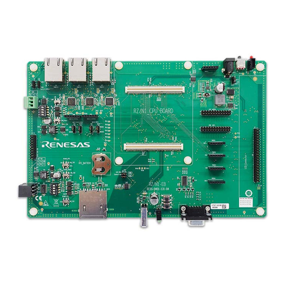
- Page 4 CONNECT IT! ETHERNET RZ/N1S-DB 2. Hardware Setup 2.1 CPU Demo Board Setup To get started quickly with the board, please identify the connectors on the RZ/N1S-DB CPU Board. Figure 2-1: Board connectors overview R01QS0021ED0060 Rev. 0.60 Page 4 of 24...
- Page 5 I-Jet Debugger Not used Not used *PHY reset available only in PMOD configuration **ARM serial debug feature is not supported with the RZ/N1S demo board from the solution kit package Table 2: RZ/N1S Boot Config DIP-Switch SW4 Default Switch SW ON (white bar)
- Page 6 RZ/N1S Group CONNECT IT! ETHERNET RZ/N1S-DB Switch On Setting (white bar) (default) Off Setting RXCLK5 from Phy RXCLK5 from GPIO61 Table 4: Jumper Settings RZ/N1S-DB USB Power Jumper On Setting (default) Off Setting CN14 Power from USB Power from expansion board...
- Page 7 RZ/N1S Group CONNECT IT! ETHERNET RZ/N1S-DB Power On Clear Switch On Setting Off Setting POR Reset Release POR Reset SW9: Soft Reset Switch On Setting Off Setting Soft Reset Release Soft Reset SW6: CM3 NMI Switch On Setting Off Setting...
- Page 8 If the board is not recognized by Windows, please install the FTDI driver that you may find under …\YCONNECT-IT-RZN_V1.x\Tools\FTDI. If the required 3.3V are supplied to RZ/N1S, the green LED24 will be lit and stay ON. R01QS0021ED0060 Rev. 0.60 Page 8 of 24...
- Page 9 RZ/N1S Group CONNECT IT! ETHERNET RZ/N1S-DB You can perform a soft-reset of the board by pressing SW9. 3. Ethernet Interface The Ethernet connection to the PC or a PLC can be prepared using one of the two RJ-45 connectors CN5 or CN1, as shown in Figure 2-5: Ethernet RJ-45 connectorsFigure 2-5. For running the EtherCAT sample program you can use any of the two connectors.
- Page 10 2.2 Expansion Board Setup If you are using the expansion board together with your RZ/N1S CPU Board, here you may find some setup notes for it. For more information refer to the board documentation in the Solution Kit. The expansion board comes with an external power supply to drive the expansion board and the RZ/N1x CPU board plugged onto the connectors J1 and J2.
- Page 11 RZ/N1S Group CONNECT IT! ETHERNET RZ/N1S-DB If using the RZ/N1-EB expansion board, please ensure the following jumper and switch settings. Table 7: Expansion Board switch settings CN10 CAN Rx Connect pins 1 and 2 (CAN2) CN11 CAN Tx Connect pins 1 and 2 (CAN2)
-
Page 12: Software Setup
The software for RZ/N1S comes as IAR compilable code and you need IAR Embedded Workbench for ARM (EWARM) for compiling and running the software on both cores. Since RZ/N1S is a dual-core device, Table 8 gives an overview of development environments for both cores. - Page 13 RZ/N1S Group CONNECT IT! ETHERNET RZ/N1S-DB Table 9: Overview of IAR Projects for RZ/N1S IAR Project Description Path to the workspace file in the Sol. Kit YCONNECT-IT-RZN_V1.x\Software\... x-ware* Set of projects Cortex A7 \ThreadX\rzn1\iar\x-ware_platform.eww running on the Cortex A7 including ThreadX,...
- Page 14 Select "libusbK" from the Target Driver list (to the right of the green arrow). Click the "Install Driver" button, this will take some time. Quit Zadig d. Locate the U-Boot binary for RZ/N1S - YCONNECT-IT-RZN_V1.X\Software\U-Boot-and-Linux\u- boot\binaries\u-boot-rzn1s324-db.bin.spkg Executes in ROM Executes in SRAM...
- Page 15 RZ/N1S Group CONNECT IT! ETHERNET RZ/N1S-DB On the board, hold down switch SW2 (to select DFU boot mode instead of QSPI) and press switch SW9 (soft reset). The RZ/N1 serial port should output: ** BOOTLOADER STAGE0 for RZN1 ** Boot source: USB Download U-Boot to SRAM.
- Page 16 RZ/N1S Group CONNECT IT! ETHERNET RZ/N1S-DB i. On the U-Boot console, run: Write U-Boot to QSPI. On your host PC run: dfu-util.exe -a "sf_uboot" -D "u-boot-rzn1s324-db.bin.spkg" in Windows sudo dfu-util -a "sf_uboot" -D u-boot-rzn1s324-db.bin.spkg in Linux Wait until it completes, the U-Boot console will prompt you to press Ctrl-C when done.
- Page 17 3.1 Running a sample application on the RZ/N1S Board It is straightforward to run an application on the RZ/N1S. Provided you followed the steps in the hardware setup chapter and in the previous chapter to write U-boot in QSPI, you need to follow the steps below to load Cortex M3 or/and Cortex A7 image in SRAM and execute it from there.
- Page 18 RZ/N1S Group CONNECT IT! ETHERNET RZ/N1S-DB 7. Click on the “Download and Debug” button in the program control panel in IAR EWARM, as shown below. 8. In the Debug Log window there should be no errors nor warnings and the program should be stopped at the beginning of the main() now.
- Page 19 A7 of RZ/N1D. Nevertheless, you can also run the non-smp projects on RZ/N1D, however smp projects will not run on the RZ/N1S, since RZ/N1S contains a single-core Cortex A7. 5. After opening the workspace, choose one of the projects in the workspace as shown below. Choose demo_threadx project as an example.
- Page 20 RZ/N1S Group CONNECT IT! ETHERNET RZ/N1S-DB 6. Compile the project by clicking “Make” 7. After the project compiled with no errors nor warnings, make sure your board is powered on and that the IAR I-Jet Debugger is connected to the JTAG connector.
- Page 21 RZ/N1S Group CONNECT IT! ETHERNET RZ/N1S-DB At the point of releasing this solution kit version, the IAR Embedded Workbench was not configured for multi- core debugging (Cortex A7 and Cortex M3 simultaneously). 3.2 Boot a sample application from QSPI flash To store your binary in QSPI Flash and be able to execute it from there after every new reset, you need to write the images in flash and set the corresponding U-Boot parameters.
- Page 22 RZ/N1S Group CONNECT IT! ETHERNET RZ/N1S-DB MMC: sdhci@0x40100000: 0 SF: Detected mx25l25635f with page size 256 Bytes, erase size 64 KiB, total 32 MiB, mapped at 10000000 serial@0x40060000 Out: serial@0x40060000 Err: serial@0x40060000 Net: , dwmac.44002000 => dfu 5. Open the command window in Windows or terminal in Linux and type the command to write the raw binary in flash: >dfu-util.exe -a "sf_cm3"...
- Page 23 RZ/N1S Group CONNECT IT! ETHERNET RZ/N1S-DB => setenv bootcmd "sf probe && sf read 0x4000000 d0000 80000 && rzn1_start_cm3" => saveenv After the next reset (SW9), the Cortex M3 image is booted and executed automatically by U-Boot. If you wish to write Cortex A7 binary in QSPI flash, you need to follow the previous steps 1-4, with the difference...
-
Page 24: Revision History
RZ/N1S Group CONNECT IT! ETHERNET RZ/N1S-DB Revision History Description Rev. Date Page Summary Draft – first revision 22.Feb.2018 23.Mar.2018 Added eth rx clk and push button settings table and dfu-util driver information 01.Aug.2018 Updates to match to the latest GOAL for solution kit v1.3.1 release 11.Sep.2018... -
Page 25: General Precautions In The Handling Of Microprocessing Unit And Microcontroller Unit Products
Unit Products The following usage notes are applicable to all Microprocessing unit and Microcontroller unit products from Renesas. For detailed usage notes on the products covered by this document, refer to the relevant sections of the document as well as any technical updates that have been issued for the products. -
Page 26: Corporate Headquarters
Renesas Electronics disclaims any and all liability for any damages or losses incurred by you or any third parties arising from the use of any Renesas Electronics product that is inconsistent with any Renesas Electronics data sheet, user’s manual or other Renesas Electronics document.
Need help?
Do you have a question about the RZ/N1S and is the answer not in the manual?
Questions and answers