Table of Contents
Advertisement
Advertisement
Table of Contents

Related Manuals for Carel FCP/1


Summary of Contents for Carel FCP/1
- Page 1 FCP/1 regulator with microprocessor control User manual...
- Page 3 CAREL or its subsidiaries are warned of the possibility of such damage.
-
Page 5: Table Of Contents
Summary table of operating parameters ..............................31 Tables of alarms and signals.....................................33 Alarms ............................................33 Signals............................................33 Supervision ..........................................34 Carel supervisor protocol....................................34 Modbus protocol ........................................34 Specifications and connections ..................................36 FCPM082010 electrical specifications ................................36 10.1 FCPM082A10 electrical specifications ................................37 10.2... -
Page 7: Introduction
- the second includes the power functions only, and can be used to double the total power available, acting as a slave to the complete controller. Alternatively, it can serve any Carel controller that features a specific phase control output (MCH*, PCO*, …). -
Page 8: User Interface
This function is used to disable the internal control algorithm and manage the output directly based on an external signal. Serial connection An RS485 serial output is available for connection via two wires plus shield to the supervisor or telemaintenance network that support the Carel supervisor protocol or ®... -
Page 9: Installation
FCP manual 3. Installation To install the controller, proceed as follows, with reference to the connection diagrams shown at the end of the manual. Important: 230 Vac mains voltage present on the board The controller may be installed outside but paying attention to the following instructions: •... - Page 10 FCP manual To ensure compliance with the safety standards, the electrical system must be fitted with a suitable switch or disconnector (compliant with standards IEC 60947-1 and IEC 60947-3), located near the appliance. If the appliance is used in a manner that is not specified by the manufacturer, the protection featured for the appliance may be compromised and the appliance may be seriously damaged.
-
Page 11: Programming The Instruments
FCP manual 4. Programming the instruments The instruments are programmed by dipswitches, trimmers and jumpers, and by setting the internal parameters accessible via programming key or via serial line. The functions that can be set manually are shown in the tables below: Dipswitch Function Dip1... -
Page 12: Default Settings
FCP manual Default settings The functions that are available by setting the parameters are mostly disabled by default, as they need to be set based on the specific application. Set the set point, differential, minimum and maximum output by trimmer (modifiable by dipswitch) Digital input ID1 external alarm (modifiable by dipswitch) Two circuit... -
Page 13: Accessories
Parameter copying key Programming key PSOPZKEY00/A0 The programming keys PSOPZKEY00 (Figure 5.1.a) and PSOPZKEYA0 (Figure 5.1.b) are used to copy the complete set of parameters relating to the CAREL FCP controller parameters. The keys must be connected to the PROG KEY connector (4 pin AMP) fitted on the controllers, and work even without switching the controller on (see the summary diagram in Figure 5.1.c.) -
Page 14: Description Of The Functions
FCP manual 6. Description of the functions Control modes The following operating modes can be set: Direct an increase in the value measured by the probes increases the value of the output; Reverse an increase in the value measured by the probes decreases the value of the output. DIRECT REVERSE 100%... -
Page 15: Two Circuit Function
FCP manual Status variables associated with the probes par. Modb range description PB1R 0 to 100 probe B1 reading as a % of the range of measurement PB2R 0 to 100 probe B2 reading as a % of the range of measurement PB1T -50.0 to +150.0 0.1°C... -
Page 16: Cut-Off Function
FCP manual Cut-off function When the output of the controller decreases until reaching the minimum value set, the output is forced to zero and remains at this value until the conditions require an output value that is greater than or equal to the minimum value set. CUT-OFF Off CUT-OFF On 100%... -
Page 17: Outside Temperature Compensation (Feedforward Function)
FCP manual Outside temperature compensation (feedforward function) The operation of the controller can be modified according to the temperature measured by probe B3, proportionally increasing the minimum output value set. This function is especially useful when probes B1 and B2 measure temperature values because, as temperature probes are intrinsically slower to respond than pressure probes, it brings forward the effects of any changes in the outside temperature, increasing the output as the outside temperature increases. -
Page 18: Slave Mode Function
FCP manual 100% diff diff diff setp 100% setp Fig. 6.f In this regard, it is good practice for the operating range of the probes to allow the set point to be set away from the extremes, by a value greater than the maximum differential envisaged. -
Page 19: Overriding The Output
FCP manual 6.11 Overriding the output The output can forced to the desired value required at any time via serial line, irrespective of the value calculated by the controller. This function is temporary and is not saved; it is disabled automatically 10 seconds after the termination of the serial connection. Associated parameters par. -
Page 20: Description Of The Operating Parameters
FCP manual 7. Description of the operating parameters type of unit type and Carel supervisor address integer var. 1 (read only) Modbus address read register 101 resolution and unit of measure range default Non-modifiable parameter used to identify the type of controller in supervision network connections or when connected to the programming key. - Page 21 FCP manual DIFF differential type and Carel supervisor address integer var. 7 Modbus address read/write register 107 resolution and unit of measure range 0 to 100 default Parameter used to set the value of the control differential. Expressed as a % of the full scale of the probes used. Only used if configuration by parameter rather than by trimmer is enabled.
- Page 22 Parameter used to select the type of probe or signal connected to input B1. PB1M=0 Carel NTC temp. probe 10kΩ @ 25°C (range of measurement -50 to 90 °C) PB1M=1 Carel NTC temp. probe 50kΩ @ 25°C (range of measurement 0 to 120 °C) PB1M=2 0/5 V ratiometric pressure probe PB1M=3 0/10 V signal (the position of jumpers JA &...
- Page 23 FCP manual DIP4 function associated with dipswitch 4 type and Carel supervisor address integer var. 20 Modbus address read/write register 120 resolution and unit of measure range 0 to 8 default Parameter used to select the function enabled/disabled by dipswitch 4 rather than by parameter.
- Page 24 FCP manual tSET SET trimmer setting type and Carel supervisor address integer var. (read only) 31 Modbus address read register 131 resolution and unit of measure range 0 to 100 default Variable used to read the value set by the trimmer...
- Page 25 FCP manual ERRR error reading type and Carel supervisor address integer var. (read only) 38 Modbus address read register 138 resolution and unit of measure range -255 to 255 default Variable used to read the value of the error (difference between the set point and the measurement of the controlled value) calculated by the control algorithm and based on which the proportional and integral components are calculated.
- Page 26 FCP manual lower limit of meas. range NTC-10k Ω type and Carel supervisor address analogue var. 2 Modbus address read/write register 2 resolution and unit of measure 0.1°C range -50.0 to T0H default -10.0 Parameter used to set the lower limit of the range of measurement for NTC-10k probes, corresponding to 0%.
- Page 27 FCP manual ESUP enable Speed-up type and Carel supervisor address digital var. 2 Modbus address read/write coil 2 resolution and unit of measure range default Parameter used to enable the Speed-up function: ESUP=0 disabled ESUP=1 enabled The parameter has no meaning if the enabling of the function Speed-up is associated with dipswitch 4 (par. DIP4).
- Page 28 FCP manual PB3E enable probe input B3 type and Carel supervisor address digital var. 8 Modbus address read/write coil 8 resolution and unit of measure range default Parameter used to enable probe input B3 and, as a consequence, the outside temperature compensation function. The reading of the probe and any alarms due to probe faults are only activated if the input is enabled.
- Page 29 FCP manual STID input ID1 status type and Carel supervisor address digital var. (read only) 17 Modbus address read coil 17 resolution and unit of measure range default Variable used to read the status of digital input ID1. STID=0 open...
- Page 30 FCP manual PB2A probe B2 alarm status type and Carel supervisor address digital var. (read only) 24 Modbus address read coil 24 resolution and unit of measure range default Variable used to read the status of the probe B2 fault alarm.
-
Page 31: Summary Table Of Operating Parameters
FCP manual Summary table of operating parameters name Carel spv var Modbus var range def. User res. description value Type of unit 0 to 255 Software release SADR 1 to 255 Serial address ( CAREL NOTE PROT UP TO STP1... - Page 32 FCP manual ELPL Enable long impulse phase control 0=disabled 1=enabled MOID Operating logic of digital input ID1 0=normally closed 1=normally open D12 to D14 12 to 14 not used EOVR Enable override output ( 0=disabled 1=enabled NOTE FDEF Reset default values ( 0=no action 1=enabled NOTE...
-
Page 33: Tables Of Alarms And Signals
FCP manual 8. Tables of alarms and signals 8.1 Alarms The alarm status is indicated by the red LED status of the red LED description possible causes of the alarm no alarm parameter error alarm non-volatile memory error (EEPROM) flashing 1 impulse probe B1 or B2 faulty alarm probes disconnected or short-circuited flashing 2 impulses... -
Page 34: Supervision
Table 9.a The protocol used is recognised automatically. If the controller is connected to a Carel supervisor, the controller will respond with the Carel protocol, similarly if the controller is connected to a Modbus supervisor, the controller will respond with the Modbus protocol. - Page 35 The use of the two function codes is identical, as no distinction is made between Holding Registers (read/write Registers) and Input Register (read only Registers from I/O devices). To map the addresses of the analogue and integer variables (according to the standard Carel protocol) in the space of Modbus addresses, the following rule has been defined:...
-
Page 36: Specifications And Connections
12 V with contact open, typical current 6 mA with contact closed. Serial outputs 1 standard RS485 two wire connector [NOTE 1] Carel supervisor and ModBus protocol; baud rate 19200; max length 1 km with shielded cable Signal lights Green power LED... -
Page 37: Fcpm082A10 Electrical Specifications
Programmable digital input. Motor protector or second set point management, see dipswitch configuration. B1, GND, +5V Analogue input for pressure (ratiometric) or temperature reading (CAREL NTC probe or 0/10 V control) in circuit 1 B2, GND, +5V Analogue input for pressure (ratiometric) or temperature reading (CAREL NTC probe) in circuit 2 NTC input for temperature reading used in the feed-forward algorithm (CAREL NTC probe).. -
Page 38: Fcpm082A10 Connections
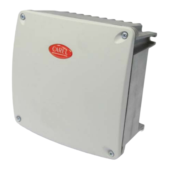
FCP manual 10.4 FCPM082A10 connections 230 V~ Fig. 10.b L, N Controller 230 Vac power supply input L1, N Power supply output to 0 to 230 Vac load Control input Y1, GND 10.5 Dimensions and assembly Fig. 10.c Code +030220391 – rel 1.1 07/11/06... - Page 40 Agenzia / Agency: CAREL S.p.A. Via dell’Industria, 11 - 35020 Brugine - Padova (Italy) Tel. (+39) 049.9716611 Fax (+39) 049.9716600 http://www.carel.com - e-mail: carel@carel.com...
Need help?
Do you have a question about the FCP/1 and is the answer not in the manual?
Questions and answers